Department of ECE, Adhiyamaan College of Engineering, Hosur, Tamilnadu, India.
Test Pattern Generation by Sharing Scan
Sequence in block level
V.Kevraj1, S.Vijayamurugan2
Student Scholar, Department of VLSI, Adhiyamaan College of Engineering, Hosur, India1
Asst. Professor, Department of ECE, Adhiyamaan College of Engineering, Hosur, India2
ABSTRACT: A approach to test application called transparent scan provides an opportunity to share tests
among different logic blocks whose primary inputs and outputs are included in scan chains even if the blocks have different numbers of state variables. A transparent-scan sequence for one block is likely to detect faults in other blocks since transparent scan does not distinguish between functional and scan clock cycles, and allows faults to be detected at all the clock cycles of the sequence. Such sharing of tests is not meaningful with conventional scan-based tests, especially when the blocks have different numbers of state variables. Transparent scan thus enhances the ability to produce a compact test set for a group of logic blocks. The static test compaction procedure described in this paper uses transparent scan sequences that follow the application of conventional scan-based tests precisely. The procedure obtains a set of transparent-scan sequences for a group of logic blocks from compacted test sets for the logic blocks in the group. From this set, it selects a subset that detects all the target faults, which are detected by the complete set.
KEYWORDS: Full-scan circuits, test compaction, test generation, transparent scan.
1. INTRODUCTION
Under an approach to test application called transparent scan [1], the scan-select and scan-chain inputs of a scan circuit are considered as inputs of the sequential circuit in the same way as the primary inputs, and the scan-chain outputs are considered as outputs in the same way as the primary outputs. A test sequence under transparent scan specifies the values for all the inputs without distinguishing between them based on their types. The corresponding output sequence specifies values for all the outputs, again, without distinguishing between them based on their types. Faults are allowed to be detected during all the clock cycles of a transparent-scan sequence. In general, fault coverage is computed by sequential fault simulation of the transparent-scan sequence.
Department of ECE, Adhiyamaan College of Engineering, Hosur, Tamilnadu, India.
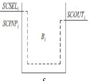
Fig. 1. Logic block.
The scan-chain input and primary input sequences are also allowed to change relative to the initial sequences. The goal in [1] was to achieve test compaction for a single logic block using a single transparent scan sequence, and changing the sequences of the various inputs contributes to test compaction. When a logic block is embedded in a design, access to its primary inputs and primary outputs, as well as its state variables, for the purpose of test application may be available only serially through scan chains. Fig. 1 illustrates such a logic block Bi with a single scan chain. The scan chain is marked with a dashed line. The scan-select input of Bi is denoted by SCSELi, its scan-chain input by SCINPi, and its scan-chain output by SCOUTi. Under the model of Fig. 1, a transparent-scan sequence for Bi specifies values only for SCSELiand SCINPi. The output sequence specifies only the corresponding values of SCOUTi. Thus, the input values are brought to all the inputs of the combinational logic serially, and the output values of all the outputs of the combinational logic are observed serially. For the discussion in this paper, every logic block Bi follows the model of Fig. 1 with serial access to all the inputs and all the outputs of its combinational logic. A transparent-scan sequence for Bi is obtained from every test in a conventional single-cycle scan-based test set of Bi . The transparent-scan sequence follows the application of the test precisely, and it is not modified. This is important for accommodating the constraints of test data compression [2]–[6]. If a conventional scan-based test set i computed under the constraints of a test data compression method, and the scan-select and scan-chain input sequences of the transparent-scan sequences based on it are not modified, the scan-chain input sequences satisfy the same constraints as the conventional tests from which they were obtained. For a logic block Bi with a scan chain of length ki, the scan-select sequence has two subsequences of ki scan clock cycles separated by a single functional clock cycle. The first subsequence of kiscan clock cycles corresponds to the scan-in operation, and the second subsequence corresponds to the scan-out operation of the test. This sequence is fixed and does not need to be stored. Under these conditions, this paper introduces the following approach to test compaction. Let B0 and B1 be two logic blocks in the same design such
that the logic blocks follow the model of Fig. 1. For i= 0 and 1, let sibe a conventional scan-based test for Bi. Let the number of flip-flops in Bi be ki. If k0 = k1, it is possible to apply s0 to B1, and s1 to B0. However, the numbers of faults that the tests detect when they are applied to a logic block other than the one they were computed for may be low.
scan-Department of ECE, Adhiyamaan College of Engineering, Hosur, Tamilnadu, India.
based test sets S0, S1,. . ., Sn−1 for logic blocks B0, B1,. . ., Bn−1, respectively. The test sets can be compacted using conventional dynamic and static test compaction procedures [7]–[19]. For 0 ≤ i< n, let Si ={si,0, si,1,. . .,
si,mi−1
II. TRANSPARENT SCAN
A transparent-scan sequence Ti, j for a logic block Bi that follows the model of Fig. 1 specifies two values at every clock cycle, the value of the scan-select input SCSELi, and the value of the scan-chain input SCINPi. The test vector at clock cycle u of Ti, j is denoted by Ti, j (u). The value of the scan-select input under Ti, j (u) is denoted by Ti, j (u, 0), and
the value of the scan-chain input is denoted by Ti, j (u, 1). For a functional clock cycle, Ti, j (u, 0) = 0. For a scan clock cycle, Ti, j (u, 0) = 1. For illustration, the next example is based on a logic block Bi with four flip-flops in its scan chain. Let Si ={0011, 0101, 1001} be a conventional single-cycle scan-based test set for Bi . The transparent-scan sequences shown
in Table I apply these tests to the circuit. Considering si,0= 0011, clock cycles 0 to 3 of Ti,0 are scan clock cycles, and they have Ti,0(u, 0) = 1 for 0 ≤ u ≤ 3. These clock cycles are used for loading the test 0011 into the scan chain.
The values of the scan-chain input, Ti,0(u, 1) for 0 ≤ u ≤ 3, correspond to this test assuming that scan chains are shifted to the right. Clock cycle 4 is a functional clock cycle, with Ti,0(4, 0) = 0. This clock cycle is used for capturing the circuit response to 0011 in the scan chain. The scan-chain input value Ti,0(u, 1) can be determined
arbitrarily, and it is marked with an “x” in Table I. Clock cycles 5 to 8 are scan clock cycles with Ti,0(u, 0) = 1 for 5 ≤ u ≤ 8. They allow the response of the circuit to 0011 to be scanned out and observed. The values of the scan-chain input Ti,0(u, 1), for 5 ≤ u ≤ 8, can be determined arbitrarily. They can be used for overlapping the
test with the next test.
In general, for a logic block Bi with kistate variables and a test si, j , the transparent-scan sequence Ti, j is defined as follows: For 0 ≤ u <ki, Ti, j (u, 0) = 1 defines scan clock cycles
for the scan-in operation of si, j. For u = ki,Ti, j (u, 0) = 0 defines a functional clock cycle where the response of the circuit to si, j is captured. For ki+1 ≤ u <2ki+1, Ti, j (u, 0) = 1 defines scan clock cycles for the scan-out operation of si, j . During the scan-in operation, Ti, j (u, 1) is determined by si, j . Assuming a scan chain that is shifted to the right and si, j =
Department of ECE, Adhiyamaan College of Engineering, Hosur, Tamilnadu, India.
higher for multipattern tests. However, the translation into transparent-scan sequences is done in the same way as for single-pattern tests, and the same static test compaction procedure can be applied. This paper considers only single-pattern tests. It considers single stuck-at faults as target faults. For the discussion in this paper, the unspecified values of a transparent-scan sequence are left unspecified. Thus, they can be used for overlapping a test with the next test after test compaction is applied. The alternative is to specify these values (e.g., randomly). However, this will prevent tests from being overlapped and potentially increase the test application time. When computing the storage requirements of a set of transparent-scan sequences, only the specified scan-chain input values are counted. This can be achieved by applying the following process.
1) The present state for the functional clock cycle can be computed without logic or fault simulation based on the values of the scan-chain input during the scan clock cycles that define the scan-in operation at the beginning of the test.
2) Combinational fault simulation is required for the functional clock cycle.
3) Based on the fault effects that are propagated to the flipflops during the functional clock cycle, and the number of scan clock cycles for the scan-out operation at the end of the test, it is possible to compute which fault effects will reach an output. For generality, sequential fault simulation is used in this paper. The test compaction procedure described in this paper uses
the observation that a transparent-scan sequence for a logic block with kistate variables can be applied to any logic block, including logic blocks where the number of state variables is
different from ki. A transparent-scan sequence is applied to a block with any number of state variables without modification. In particular, the functional clock cycle of a transparent-scan
sequence that was generated for a logic block with kistate variables remains at clock cycle ki. For example, suppose that Ti,0 from Table I is applied to a logic block with five state variables. Starting from the all-unspecified (all-x) initial state, clock cycles 0 to 3 of Ti,0 bring the circuit with five state variables into the state 0011x. A functional clock cycle at clock cycle 4 of Ti,0 causes the scan chain to capture the circuit response to 0011x. This includes the effects of faults that are detected by 0011x. Some of these fault effects may be scanned out during clock cycles 5 to 8.
If Ti,0 from Table I is applied to a logic block with three state variables, clock cycles 0 to 2 bring the circuit into state 011. Clock cycle 3 brings the circuit into state 001.
A functional clock cycle at clock cycle 4 of Ti,0 causes the scan chain to capture the circuit response to 001. Clock cycles 5–7 are sufficient for observing the values of all the
flip-flops. This example illustrates the following point. Suppose that two logic blocks B0 and B1 with numbers of state variables k0 and k1, respectively, are such that k0 > k1. A
transparent-scan sequence T0, j0 of B0, when applied to B1, results in a fully specified state during the functional clock cycle at clock cycle u = k0. A transparent-scan sequence
T1, j1 of B1, when applied to B0, results in an incompletely specified state during the functional clock cycle at clock cycle u = k1. Therefore, it is more likely for T0, j0 to detect faults in B1 than for T1, j1 to detect faults in
B0. Nevertheless, sharing of both types of sequences is possible. In both cases, the transparent-scan sequences of B1 (B0) assign
input values that can be considered as arbitrary when they are applied to B0 (B1). The ability of these sequences to detect faults is similar to that of random tests. It is enhanced by the ability of transparent scan to detect faults at all the clock cycles of a sequence process for multiple logic blocks in a design are not considered here. Test scheduling in general was discussed, e.g., in [11].
III. TEST COMPACTION PROCEDURE
Department of ECE, Adhiyamaan College of Engineering, Hosur, Tamilnadu, India.
{si,0, si,1,. . ., si,mi−1}. For 0 ≤ i< n and for 0 ≤ j <mi , the procedure translates si, j into a transparent-scan sequence Ti, j as described in the previous section. It then adds Ti, j to T . It is possible to use a set covering procedure in order to select a subset of T that detects all the faults in F. Set covering procedures for test compaction were described in [13], [15], [16], [18], and [19]. However, a set covering procedure requires information about all the sequences from T that detect every fault in F. This requires fault simulation without fault dropping, and has a high computational complexity. Instead, the selection of a subset of T proceeds in two steps, which are motivated by the approach that was used in [12] as part of a dynamic test compaction procedure for conventional scan-based test sets, and in [18] as part of a static test compaction procedure for nonscan sequential circuits. In the context of transparent scan, the two steps proceed as follows.
Step 1 selects a subset Tsel1 ⊆T by identifying faults from F that are detected by unique sequences in T . If a fault f ∈F has only one transparent-scan sequence Ti, j ∈T that detects it, Ti, j must be included in the selected subset of transparent scan sequences. In this case, Ti, j is included in Tsel1. Step 2 selects additional transparent-scan sequences as necessary to produce a subset Tsel2 that detects all the faults in F. The details of the two steps are described next. Step 1 performs two-detection fault simulation of the faults in F under the transparent-scan sequences in T . The number of detections of a fault f ∈F is equal to the number of sequences from T that detect the fault. The two-detection fault simulation procedure drops a fault from further simulation after it finds two transparent-scan sequences in T that detect the fault.It stores the number of times a fault f ∈F is detected during this process in a variable denoted by ndet( f ). It stores the index of the first transparent-scan sequence that detects a fault f ∈F in a variable denoted by first( f ).
Department of ECE, Adhiyamaan College of Engineering, Hosur, Tamilnadu, India.
consideration as early as possible. For illustration, the next example considers a group of logic blocks where B0 is ISCAS-89 benchmark s27, B1 is ITC-99 benchmark b01, and B2 is ITC-99 benchmark b02. The numbers of state variables for these circuits are k0 = 8, k1 = 10 and k2= 7.
IV. EXPERIMENTAL RESULTS
The static test compaction procedure described in Section III was applied to groups of circuits consisting of ISCAS-89, ITC-99, and IWLS-05 benchmarks. The set of target faults includes the single stuck-at faults of all the logic blocks in a group. The conventional single-pattern test sets used for the blocks were compacted by dynamic and static test compaction, and they contain no or a small number of unnecessary tests. The use of transparent scan can also make a small number of sequences unnecessary. To collect information about the numbers of transparent-scan sequences of a block, the static test compaction procedure was first applied to each block alone (the block was placed in a group by itself). The only blocks where the number of transparent-scan sequences was smaller than the number of conventional scan-based tests are the following: For s386, the conventional scan-based test set consists of 70 tests, and the static test compaction procedure selects 68 transparent-scan sequences. For s1196, the conventional scan-based test set consists of 138 tests, and the static test compaction procedure selects 133 scan sequences. For all the other blocks, all the transparent-scan sequences based on the conventional transparent-scan-based test set are necessary when each one of the blocks is included alone in a group. To define the groups, the circuits were arranged by order of increasing number of state variables. Group n consists of the first n circuits in the ordered list, for n = 1, 2, 3,. . ., 32. The importance of the number of state variables was discussed earlier. It is related to the fact that a transparent-scan sequence for a block with k0 state variables is more likely to detect faults in a block with k1 state variables if k0 ≥ k1 than if k0 < k1. Column S shows information about the conventional scan based test sets of the blocks. Subcolumn Tests shows the number of tests, and subcolumn Bits shows the number of bits required for storing each test set. Columns T sel1 and T sel2 show information about the sets Tsel1 and Tsel2 of transparent-scan sequences, respectively. SubcolumnSeq shows the number of sequences in Tsel1 or Tsel2 that belong to each one of the blocks. Subcolumn Bits shows the number of bits required for storing all the sequences corresponding to each block. Subcolumn Ratio shows the ratio where the number of bits required for the sequences in Tsel2 that belong to the block is divided by the number of bits required for the conventional scan-based test set of the block (the ratio is also equal to the number of sequences in Tsel2 that belong to the block divided by the number of conventional scan-based tests of the block). In row Total, the second to the eighth columns show the sums of the numbers in the corresponding columns. Column Ratio shows the ratio where the number of bits required for all the sequences in Tsel2 is divided by the number of bits required for all the conventional scan-based test sets. The following points can be seen from Tables III–VII. The conventional test sets that are used for the logic blocks do not contain unnecessary tests, or contain small numbers variables or significantly more transparent-scan sequences than the other blocks in the group.
Department of ECE, Adhiyamaan College of Engineering, Hosur, Tamilnadu, India.
This happens, for example, when pci_spoci_ctrl, with 148 conventional scan-based tests, is added to form the group with n = 24. It also happens when usb_phy, with 130 state variables, is added to form the group with n = 25. It happens again when s5378, with 263 state variables and 100 conventional scan-based tests, is added to form the group with n = 29, and when s9234, with 269 state variables and 111 conventional scan-based tests, is added to form the group with n = 30. Even with these increases, the reduction in the storage requirements remains significant in all the cases, and it is always preferable to use groups that are as large as possible. In addition, sharing of transparent-scan sequences reduces the effects of these blocks when blocks with larger numbers of state variables are added to the group. This observation is related to the following points. In general, the reduction in the numbers of transparent-scan sequences is larger for the blocks with the smaller numbers of state variables, and smaller for the blocks with the larger numbers of state variables in a group. In particular, for the logic blocks with the largest numbers of state variables in a group, it is typically necessary to select all or almost all for s386 is equal to 0.97 when n = 1, 0.87 when n = 2, 0.84 when n = 3, 0.79 when n = 4, 0.74 when n
= 5, and so on.
Considering b09, all of its transparent-scan sequences are selected as part of the group with n = 6, where it has the largest number of state variables. All of its transparent-scan sequences are also selected as part of the groups with n ≤ 10. The fraction of transparent-scan sequences for b09 reduces to 0.60 when n = 11, to 0.56 when n = 13, and so on. For s382, all of its transparent-scan sequences are needed when it appears for the first time in the group with n = 4. None of its transparent-scan sequences is selected when n ≥ 22. Most of the sequences that are included in Tsel2 are selected in Step 1. These sequences will be selected by any covering procedure since they are necessary for detecting some of the target faults. Only a small number of sequences are typically added in Step 2. This justifies the use of fault simulation with fault dropping for Step 2, alleviating the need for more complex fault simulation procedures. A related parameter is the fault coverage achieved after Step 1 and the percentage of faults that remains to be detected in Step 2. Information about these percentages is given in column f.c. of Tables VIII and IX for some of the groups. Sub column T sel1 shows the fault coverage achieved by all the transparent-scan sequences that are selected in Step 1 and subcolumnT sel2 shows the fault coverage achieved after additional transparent-scan sequences are selected in Step 2. For a given logic block, the fault coverage obtained after Step 1 initially decreases as larger blocks are added to the group and more transparent-scan sequences are available. Eventually, the fault coverage after Step 1 saturates when the addition of logic blocks to the group does not affect the selection of transparent-scan sequences for the block in a significant way. In addition, since Step 2 is based on fault simulation with fault dropping, application of Step 2 is manageable even when the fault coverage achieved after Step 1 is lower. The computational complexity of the static test compaction procedure is determined by the need to perform doubledetection fault simulation of the logic blocks in the group under the set of transparent-scan sequences T , which is defined based on their conventional test sets.
The runtime for doubledetection fault simulation is not higher than twice that for fault simulation with fault dropping. The runtime increases with n since more transparent-scan sequences are included in T as n is increased, and the sequences are longer as blocks with larger numbers of state variables are included in the group. To demonstrate the effect of the number of transparent-scan sequences in T on the runtime, Fig. 3 focuses on B0 = s386 in the groups of sizes 1 ≤ n ≤ 32. Let the runtime for double detection fault simulation of s386 as part of the group of size n be RT0,n. Let the number of transparent-scan sequences in T for a group of size n be
Mn. For 1 ≤ n ≤ 32, there is a circle in Fig. 3 corresponding to Mn/M1 and RT0,n/RT0,1. The dashed line shows what the runtime would have been if it had increased linearly with the number of transparent-scan sequences in
Department of ECE, Adhiyamaan College of Engineering, Hosur, Tamilnadu, India.
increase if longer transparent-scan sequences are used for it when it is tested as part of the group. To assess the test application time for a logic block Bi as part of a group, the following computation is used.
Suppose that the set of transparent-scan sequences Tsel2 is selected for the group, and the subset Tsel2,i⊆Tsel2 is selected for testing Bi . Considering a transparent-scan sequence Tsel2,i, the contribution of Tˆi, ˆj to the test application time for Bi is approximately kˆi. This is the number of state variables of the logic block Bˆifor which
Tˆi, ˆj was generated. If the scan-in operation of Tˆi, ˆj is overlapped with the scan-out operation of the previous test, Tˆi, ˆj adds kˆi+ 1 clock cycles. This information is shown in column applic of Tables VIII and IX for the logic blocks in some of the groups. Sub column S shows the estimated test application time for the conventional scan-based test set of each logic block. Subcolumn Tsel2 shows the estimated test application time for the transparent-scan sequences that are selected for the logic block by the static test compaction procedure. Considering a logic block Bi , the test application time for Bi starts from a value that is close to that of the conventional scan-based test set when Bi is one of the largest blocks in the group. The test application time for
Bi increases as additional logic blocks are added to the group. The increase occurs since the new logic blocks that are added to the group have more state variables than Bi , and their transparent-scan. sequences have a higher contribution to the test application time when they are selected for Bi However, the highest test application times are obtained for the largest blocks in the group, and these test application times are close to the test application times for the conventional scan-based test sets. These are expected to dominate the test application time for the group as a whole.
V. CONCLUSION
This paper described a test compaction procedure under transparent scan for groups of logic blocks whose primary inputs and outputs are scanned. The procedure accepts conventional compacted single-cycle scan-based test sets for the logic blocks. It translates them into a set of transparent scan sequences, which can be shared among the logic blocks. Using two-detection fault simulation followed by fault simulation with fault dropping, the procedure selects a subset of transparent-scan sequences for detecting all the target faults in all the logic blocks of the group. Experimental results showed that transparent-scan sequences based on tests for one logic block could detect faults in other logic blocks, with different numbers of state variables. This allowed a reduced number of transparent-scan sequences to be used for the group. Transparent-scan sequences of logic blocks with higher numbers of state variables typically detected faults of logic block with smaller numbers of state variables. This was themain contributor to the reduction in the number of transparent scan sequences for the group.
REFERENCES
[1] I. Pomeranz and S. M. Reddy, “A new approach to test generation and test compaction for scan circuits,” in Proc. Design Autom. Test Eur.Conf., 2003, pp. 1000–1005.
[2] K. Lee, J. Chen, and C. Huang, “Using a single input to support multiple scan chains,” in Proc. Int. Conf. Comput.-Aided Design, 1998, pp. 74–78.
[3] C. Barnhart, V. Brunkhorst, F. Distler, O. Farnsworth, B. Keller, and B. Koenemann, “OPMISR: The foundation for compressed ATPG vectors,” in Proc. Int. Test Conf., 2001, pp. 748–757.
[4] B. Koenemann, C. Barnhart, B. Keller, T. Snethen, O. Farnsworth, and D. Wheater, “A SmartBIST variant guaranteed encoding,” in Proc. AsianTest Symp., 2001, pp. 325–330.
[5] J. Rajski, J. Tyszer, M. Kassab, N. Mukherjee, R. Thompson, K.-H. Tsai, A. Hertwig, N. Tamarapalli, G. Mrugalski, G. Eide, and . Qian, “Embedded deterministic test for low cost manufacturing test,” in Proc. Int. Test Conf., 2002, pp. 301–310.
[6] N. A. Touba, “Survey of test vector compression techniques,” IEEE Design Test Comput., vol. 23, no. 4, pp. 294–303, Apr. 2006.[7] P. Goel and B. C. Rosales, “Test generation and dynamic compactionof tests,” in Proc. Test Conf., 1979, pp. 189–192.
[7] I. Pomeranz, L. N. Reddy, and S. M. Reddy, “COMPACTEST: A method to generate compact test sets for combinational circuits,” in Proc. Int.Test Conf., 1991, pp. 194–203.
[8]J.-S. Chang and C.-S. Lin, “Test set compaction for combinational circuits,” in Proc. Asian Test Symp., 1992, pp. 20–25.
Department of ECE, Adhiyamaan College of Engineering, Hosur, Tamilnadu, India.
[10]M. Abramovici, M. A. Breuer, and A. D. Friedman, Digital Systems Testing and Testable Design. Piscataway, NJ, USA: IEEE Press, 1995.
[11] S. Kajihara, I. Pomeranz, K. Kinoshita, and S. M. Reddy, “Cost-effective generation of minimal test sets for stuck-at faults in combinational logic circuits,” IEEE Trans. Comput.-Aided Design, vol. 14, no. 12, pp. 1496–1504, Dec. 1995.
[12] D. S. Hochbaum, “An optimal test compression procedure for combinational circuits,” IEEE Trans. Comput.-Aided Design, vol. 15, no. 10, pp. 1294–1299, Oct. 1996.
[13] I. Hamzaoglu and J. H. Patel, “Test set compaction algorithms for combinational circuits,” in Proc. Int. Conf. Comput.-Aided Design, 1998, pp. 283–289.
methanamine oxide](data:image/gif;base64,R0lGODlhAQABAIAAAP///wAAACH5BAEAAAAALAAAAAABAAEAAAICRAEAOw==)