GENERAL PLASTIC COLLAPSE LOAD EQUATIONS OF PIPE BEND
WITH OR WITHOUT CRACK UNDER IN-PLANE BENDING
Suneel K. Gupta1, Vivek Bhasin1, K. K. Vaze1, A.K.Ghosh2
1Reactor Safety Division, Bhabha Atomic Research Centre, Mumbai, INDIA-400085
2Health Safety and Environment Group, Bhabha Atomic Research Centre, Mumbai, INDIA-400085 E-mail of corresponding author: [email protected]
ABSTRACT
Elbows exhibit highly strained regions and are vulnerable to plastic collapse. It has been observed that available equations in literature for evaluation of plastic collapse load of a pipe bend have limited applicability and do not cover wide range of pipe bend radius ratios and bend angles which are used in power plant piping. Moreover, the elbow collapse load equation should approach to straight pipe collapse load as elbow bend radius increases or bend angle decreases. Generally, the available equations do not satisfy this asymptotic behaviour of an elbow. About 600 number of elastic plastic and geometric nonlinear finite element analyses of elbows having different geometric parameters bend radius, pipe radius, thickness and crack size (in case of cracked elbow), have been performed.For each of the elbow the in-plane plastic collapse moments have been evaluated from M-rotation curve by twice elastic slope (TES) method. Further two weakening factors were defined to quantify the degrees in plastic collapse moment, one due to elbow doubly curved geometry and second due to presence of crack. The geometric weakening factor was evaluated by comparing elbow plastic collapse moment with corresponding straight pipe collapse load while the crack weakening factor was evaluated by comparing cracked elbow plastic collapse moment with corresponding un-cracked elbow plastic collapse moment. The simple equation were developed for these weakening functions which can be used with pipe plastic collapse load equation for prediction of plastic collapse load of elbows.
INTRODUCTION
Failure resistant design of any structure or component has always been the objective of designer. Pipe bends or elbows being more flexible among other piping components generally are more vulnerable for plastic collapse during the design basis accident events. Hence to prevent pipe bends failing due to plastic instability or by excessive plastic deformations, the integrity assurance needs accurate plastic collapse load information. In recent past, considerable research has been done to develop accurate plastic collapse equations of straight pipe with or without cracks, and to limited extent for pipe bend or elbow with or without cracks. However, presently available plastic collapse load equations for pipe bends have limited range of applicability and generally do not cover wide range of bend geometry, such as different bend angles and bend radius. Ideally, the elbow plastic collapse load should approach to straight pipe plastic collapse load on increasing of pipe bend radius or/and on reducing the pipe bend angle. Similar asymptotic trend is expected for the elbows with circumferential through wall cracks. The plastic collapse load solutions for cracked elbows are required during their integrity demonstration in leak before break design. The presently available plastic collapse equation of pipe bends with or without cracks do not satisfy the above asymptotic tends and have limited applicability in term of bend radius and bend angles of pipe bend.
evaluated. The elbow plastic collapse load can be obtained from corresponding pipe collapse load by multiplying it with applicable weakening factors W and H. The weakening factors W and H dependence on the R/t, rb/R, bend angle, crack angle and elbow characteristic (λ) was studied. Finally simple expressions for above weakening factors, W and H, were developed for closing and opening bending which covered the entire domain of the parameters. These developed equation satisfies the asymptotic trends like when rb/R tends to infinity or/and bend angle tends to zero, the elbow geometry weakening factor (W) approaches to unity. Similarly for cracked elbows, the crack weakening factor (H) tends to corresponding value for straight pipe (h) when rb/R tends to infinity or/and bend angle ψ tends to zero. The developed closed form equations for weakening factors were validated with recent literature equations in their validity range and the goodness of the fitting have also been checked with the FE evaluated values for these factors. They were found in good agreement and mostly within ±5% error band.
OVERVIEW OF ELBOW PLASTIC COLLAPSE LOAD EQUATIONS
Most of the elbow plastic collapse moment ( ) equations available in literature, relates it to the corresponding of straight pipe ( ) through a weakening function (Wf). The geometry weakening factor Wf, basically quantifies the loss in load carrying capacity of an elbow due to its doubly curved geometry, with respect to corresponding pipe and is defined as below.
(1)
The Wf depends on the elbow characteristic parameter, λ defined as / . Here rb is pipe bend radius, R is pipe mean radius and t is pipe wall thickness. The plastic collapse load of elbow may further decrease due to presence of cracks. A crack weakening factor H(θ) may be defined as ratio of the cracked elbow plastic collapse load ( ) to the corresponding healthy elbow plastic collapse load ( ). Hence the equation for elbow plastic collapse load (with or without crack) may be given in following general form.
(2)
Here, is plastic collapse load of corresponding pipe. For defect free elbows, H(θ) is equal to 1. The plastic collapse load ( ) of straight pipe under bending load is given as
M L 4 R t σ (3)
It may be noted that the Eq.3 of pipe PCL is based on thin shell theory. For thick pipe PCL calculation, an additional correction factor is generally used and is given in Zahoor [9]. However, the Eq. 3 is popular and mostly used for pipe PCL calculation and in present study also, this was adopted for normalising the elbow PCL. Hence the Wf and H(θ) in Eq.2 must be used with PCL of pipe evaluated using Eq.3. Here, the material constitutive behaviour is assumed as elastic perfectly plastic and σy is the yield stress. The crack weakening factor for a through-wall circumferential cracked straight pipe is given as
h θ Cos θ/2 Sin θ (4)
In past many investigators [1-9] have proposed equations to evaluate plastic collapse load of an elbow under in-plane bending. Most of these equations have been derived from finite element analysis of standard elbows (where bend radius is 1.5 times of pipe diameter) or short radius elbow (where bend radius is equal to pipe diameter). These expression are not general since they does not satisfy following asymptotic behaviour
– For a given pipe section, when the bend radius is increased the collapse load of the elbow must approach to the collapse load of corresponding straight pipe
– For a given pipe section, when the bend angle of the elbow is reduced the collapse load of the elbow must approach to the collapse load of corresponding straight pipe
In other word under above two asymptotic conditions the elbow geometry weakening factor, should approach to 1.0 and the crack weakening factor H(θ) should approach to corresponding pipe h(θ). Below is the summary of plastic collapse equations, geometry weakening factor and crack weakening factor H(θ), developed over year, available in literature. Spence and Findlay [1] obtained expression for in-plane lower bound limit moment of an elbow as
E CL
f P
CL
M Collpase Load of Elbow W
Collpase Load of Pipe M
1.45 λ for 1.0
1.45 λ for 0.8λ
Wf 0.6
> =
≤
= (5)
The Section III of ASME Boiler and Pressure Vessel Code, (ASME) [2] allows designing of piping and piping components against plastic collapse by simplified analysis using stress indices and following equation.
o o
1 2 m
PD D
B B M 1.5S
2t + 2I ≤ where B2=1.3/λ
2/3 (6)
Here B1 and B2 are stress indices for internal pressure and bending. For elbows, in absence of internal pressure, the elbow collapse load, based on the ASME B2 stress index (which is equivalent to inverse of weakling factor), are in good agreement with the lower bound limit load given by Spence and Findlay [1]. Calladine [3] has developed in-plane lower bound limit moment as
5
λ
for
λ
935 . 0
W 23
f = ≤ (7)
Both the above given theoretical expressions (Eq.6 and Eq.7) were based on small displacement analyses and assume ideal plastic material behaviour. Based on large displacement analysis Goodall [4] proposed the maximum load carrying capacity of the defect free elbow subjected to closing bending moment as
for λ 5 Where
(
, ,E, ,R/t)
1λ 04 . 1
Wf 23 ≤ β=βλ σo ν
β +
= (8)
Based on experimental investigations, Touboul [5] has proposed different equations for collapse load under in-plane closing bending and in-plane opening bending.
(Opening)
0.722 and (Closing)
0.715
W 23 13
f = λ = λ (9)
Based on large number of finite element analyses, Chattopadhayay [6] has also proposed an equation for collapse moment of elbow considering pipe constraining effect and material as an elastic perfectly plastic and geometry nonlinearity in the analysis.
(Opening)
0.0617 -1.048 W
and (Closing)
1.075
Wf = λ23 f = λ13 (10)
Recently, Y.J.Kim [7] has given a equation for collapse moment of elbow under closing bending moment based on large displacement analysis and wide range of combinations of rb/R and R/t but the resulting values of λ are limited from λ=0.1 to λ=0.5. It was shown that collapse moment not only depends on λ but also on R/t ratio.
( )
( )
( )
0.127 c0.311 c
0.017 c
n c c
f A (λ K ) Where, A 0.800R/t ; K 1.460R/t ; n 0.423R/t
W = + c = − = − = (11)
For elbows with circumferential cracks, Miller [8] was the first to propose, the plastic collapse moment equation for a elbow with through-wall circumferential cracks based at extrados subjected to in-plane bending moment, the is used as given by Calladine, eq.5, and H(θ) is given as below
( )
2π3θ
1
θ
H = − (12)
Zahoor [9] proposed a plastic collapse moments of through wall circumferential cracked elbows under in-plane bending moment where the is used as given by Calladine, and H(θ) as given below
( )
3D a 1.0559 2
D a 0.0485 D
a 0.2137 1
θ
H ⎟
⎠ ⎞ ⎜ ⎝ ⎛ − ⎟ ⎠ ⎞ ⎜ ⎝ ⎛ − ⎟ ⎠ ⎞ ⎜ ⎝ ⎛ −
= (13)
Where a = 0.5*D*θ and D is mean diameter. This has applicability, where a/D<0.8, λ<0.5, and D/t>15. Recently Chattopadhayay [6] carried out large number of FE calculations on through wall circumferential cracked elbows and proposed a series of equations for crack weakening function for opening and closing bending loadings for various applicability ranges. For opening bending moment, the H(θ) is given by eq.-14 while for closing bending moment a set of equations for several R/t and crack size applicability ranges was given. The geometry weakening factor is used as given by eq.10
( )
1 0.8 for 2 45o and H( )
1.127 1.8108 for 45o 2 150oH ⎟ ≤ θ≤
⎠ ⎞ ⎜ ⎝ ⎛ π θ −
= θ ≤
θ ⎟
⎠ ⎞ ⎜ ⎝ ⎛ π θ − =
θ (14)
this asymptotic behaviour. All equations, except Eq.6 and Eq.9 assume that any two elbows with same elbow characteristic (λ) will have same Wf. Keeping this fact in mind, a series of finite element analyses of elbows having different geometric parameters bend radius, pipe radius and thickness have been performed.
FINITE ELEMENT ANALYSES
Rigorous elastic plastic finite element analyses of around 600 elbows were carried out covering wide range of elbow geometry parameters such as elbow bend radius (rb) to mean pipe radius (R) ratio and pipe radius (R) to thickness (t) ratio, pipe bend angle (ψ), and crack sizes (θ/π) for cases of cracked elbows. The geometric details are given in Table-1. It shows that there are several elbows with equal elbow characteristic, λ, while their R/t and rb/R are different.
Table 1: Geometry details of the elbows analyzed (Mean Pipe Radius, R=250mm) Bend radius, rb/R : 2, 3, 6, 9, 12 and 18 Note: R is taken as 250 mm rb/r
Æ 2 3 6 9 12 18
R/t ↓ Elbow Characteristics, λ = (rb/r) / (R/t)
Pipe radius, R/t :5, 7.5, 10, 15, 20 and 30 5 0.4 0.6 1.2 1.8 2.4 3.6
7.5 0.4 0.8 1.2 1.6 2.4
Bend angle, ψ :30, 45, 60, 90, 135, 150 degrees 10 0.2 0.3 0.6 0.9 1.2 1.8
15 0.2 0.4 0.6 0.8 1.2
Crack size, θ/π :0 (healthy or defect free) & 0.1, 0.2, 0.3, 0.4, 0.5 (through wall circumferential) 20 0.1 0.15 0.3 0.45 0.6 0.9 30 0.1 0.2 0.3 0.4 0.6
Due to double symmetry, one quarter of the elbow was modelled using three dimensional 20 noded brick elements with connected pipes with length equal to 3 times pipe diameter on both elbow end in order to account for constraint effect posed by connected piping. The material constitutive behaviour is assumed as elastic perfectly plastic and finite element analysis was performed including the geometric nonlinearity effects. The material’s Young’s Modulus, yield stress and Poisson’s ratio is taken equal to 203GPa, 250 MPa and 0.3 respectively. Figure 1 shows meshes for two typical cases, small bend radius thin elbow (rb/R=2 and R/t=30) and other extra large bend radius thick elbow (rb/R=9 and R/t=5). Pure in plane bending moment has been applied to the end plane of connected straight pipe. Here, it is observed that under closing bending the M-φ curve becomes almost flat or some time starts decreasing after certain load while under opening bending it continues to rise as the applied moment increases. This is due to the difference in the deformation (ovalization) behaviour of elbow cross-section (see Fig.2) when subjected to closing bending, the elbow geometrically softens and for opening bending, it geometrically hardens. The collapse moments have been evaluated from M-φ curve by twice elastic slope (TES) method. If the TES line intersect the M-φ curve after maximum moment (generally happens for very thin elbows under closing bending), the plastic collapse moment is taken equal to the maximum moment on the M-φ curve. For the cracked elbow plastic collapse load evaluation, the circumferential through wall crack is modelled at extrados or intrados depending on the mode of bending moment applied. The extrados crack is assumed for closing mode of bending moment and intrados crack is assumed for opening mode of bending moment. The analyses for healthy elbow, under closing bending, were performed at all stations of pipe geometry R/t, bend radius rb/R, and bend angle ψ. In past, Gupta [10] has reported some of the results that is for all R/t, rb/R but for bend angle of 90° alone, for healthy elbow, under closing bending. Here the data were presented in context of ASME B2 stress index which intend to ensure integrity of elbows against plastic collapse mode of failure. In case of opening bending load, only selected station of R/t, rb/R and ψ were analysed. In case of cracked elbow, for both opening & closing bending load, the analyses were carried out only at selected station of R/t, rb/R and for ψ=90°.
EVALUATION OF WEAKENING FACTORS
Fig.1: Typical FE meshes (a) small rb thin elbow, rb/R=2 & R/t=30 (b) extra large rb thick elbow, rb/R=9 & R/t=5
Fig.2: Typical M-φ curve for closing & opening moment, evaluation using TES method Table-2: Geometric weakening factor, Wf , for Elbow subjected to in-plane bending
Wf for Closing Bending Wf for Closing Bending Wf for Opening Bending
rb/R→ 2 3 6 9 12 18 rb/R→ 2 3 6 9 12 18 rb/R→ 2 3 6 9 12 18
R/t ↓ Bend Angle ψ=30° R/t ↓ Bend Angle ψ=45° R/t ↓ Bend Angle ψ=45°
5.0 0.88 0.91 0.94 0.96 0.97 0.97 5.0 0.80 0.85 0.92 0.95 0.96 0.97 5.0 0.86 0.90 0.94 0.96 0.97 7.5 0.80 0.83 0.89 0.92 0.94 0.96 7.5 0.70 0.75 0.84 0.90 0.93 0.96 7.5 0.84 0.94 0.97 10.0 0.72 0.76 0.83 0.87 0.90 0.94 10.0 0.61 0.66 0.76 0.83 0.88 0.94 10.0 0.75 0.79 0.86 0.91 0.94 0.96 15.0 0.61 0.64 0.72 0.77 0.81 0.87 15.0 0.49 0.53 0.63 0.70 0.76 0.86 15.0 0.72 0.80 0.86 0.94 20.0 0.53 0.56 0.63 0.68 0.72 0.79 20.0 0.41 0.45 0.53 0.60 0.66 0.76 20.0 0.64 0.75 0.86 0.92 30.0 0.43 0.45 0.51 0.55 0.59 0.65 30.0 0.32 0.35 0.41 0.47 0.51 0.60 30.0 0.63 0.71 0.77 0.82 0.89 R/t ↓ Bend Angle ψ=60° R/t ↓ Bend Angle ψ=90° R/t ↓ Bend Angle ψ=90°
5.0 0.74 0.80 0.91 0.95 0.96 0.97 5.0 0.65 0.74 0.90 0.95 0.96 0.97 5.0 0.72 0.80 0.93 0.96 0.97 7.5 0.62 0.68 0.81 0.89 0.93 0.96 7.5 0.53 0.60 0.78 0.88 0.93 0.96 7.5 0.70 0.93 0.97 10.0 0.53 0.59 0.72 0.81 0.87 0.94 10.0 0.44 0.51 0.67 0.79 0.87 0.93 10.0 0.55 0.62 0.79 0.89 0.93 0.96 15.0 0.41 0.46 0.57 0.66 0.74 0.85 15.0 0.33 0.39 0.52 0.62 0.72 0.85 15.0 0.48 0.69 0.81 0.94 20.0 0.34 0.38 0.48 0.56 0.62 0.74 20.0 0.27 0.31 0.42 0.51 0.59 0.73 20.0 0.42 0.63 0.83 0.91 30.0 0.25 0.29 0.37 0.42 0.47 0.56 30.0 0.20 0.24 0.32 0.39 0.45 0.56 30.0 0.44 0.57 0.68 0.78 0.87 R/t ↓ Bend Angle ψ=150° R/t ↓ Bend Angle ψ=135° R/t ↓ Bend Angle ψ=135°
5.0 0.57 0.68 0.89 0.95 0.96 0.97 5.0 0.58 0.69 0.89 0.95 0.96 0.97 5.0 0.64 0.76 0.92 0.96 0.97 7.5 0.44 0.53 0.75 0.88 0.93 0.95 7.5 0.45 0.54 0.76 0.88 0.93 0.95 7.5 0.63 0.93 0.96 10.0 0.36 0.44 0.63 0.78 0.87 0.93 10.0 0.37 0.45 0.64 0.78 0.87 0.93 10.0 0.46 0.55 0.77 0.88 0.93 0.95 15.0 0.27 0.33 0.48 0.60 0.71 0.84 15.0 0.28 0.34 0.48 0.61 0.71 0.84 15.0 0.46 0.66 0.80 0.93 20.0 0.22 0.27 0.39 0.49 0.58 0.74 20.0 0.23 0.27 0.39 0.50 0.58 0.71 20.0 0.34 0.57 0.82 0.90 30.0 0.16 0.20 0.29 0.36 0.43 0.55 30.0 0.17 0.20 0.29 0.36 0.43 0.54 30.0 0.37 0.52 0.65 0.75 0.84
Fig. 3: Surface plots of FE evaluated Wf for R/t 5, 15 and 30 elbows under closing bending
Table-3: Crack weakening factor H(θ), for elbows with ψ=90° and subjected to in-plane bending H(θ) for Closing Bending (Extrados Crack) H(θ) for Opening Bending (Intrados Crack)
rb/R→ 2 3 6 9 12 18 rb/R→ 2 3 6 9 12 18
R/t ↓ Crack Angle θ/π=0.1 R/t ↓ Crack Angle θ/π=0.1
5.0 1.00 1.00 0.97 0.95 5.0 0.96 0.96 0.93 0.94
7.5 1.00 0.97 7.5 0.98 0.94
10.0 1.01 1.03 1.00 0.98 0.98 10.0 0.98 0.98 0.97 0.94 0.92 15.0 1.02 1.00 1.02 1.02 15.0 0.98 0.98 0.98
20.0 1.00 0.99 20.0 0.98 0.99
30.0 0.99 1.03 1.03 30.0 1.01 1.03 1.00 0.97
R/t ↓ Crack Angle θ/π=0.2 R/t ↓ Crack Angle θ/π=0.2
5.0 0.94 0.91 0.83 0.79 5.0 0.82 0.80 0.76 0.76
7.5 0.97 0.83 7.5 0.85 0.76
10.0 1.02 1.02 0.95 0.83 0.79 10.0 0.89 0.87 0.82 0.76 0.75 15.0 1.02 1.00 0.98 0.85 15.0 0.91 0.87 0.84 0.79
20.0 1.00 0.97 20.0 0.91 0.86
30.0 1.00 1.02 1.02 1.00 30.0 0.97 0.96 0.91 0.83
R/t ↓ Crack Angle θ/π=0.3 R/t ↓ Crack Angle θ/π=0.3
5.0 0.77 0.73 0.63 0.61 5.0 0.61 0.60 0.58 0.60
7.5 0.81 0.63 7.5 0.64 0.57
10.0 0.90 0.88 0.79 0.64 0.60 10.0 0.67 0.65 0.62 0.58 0.57 15.0 0.96 0.89 0.84 0.64 15.0 0.70 0.67 0.64 0.60
20.0 0.95 0.86 20.0 0.71 0.66
30.0 1.00 0.98 0.96 0.92 30.0 0.78 0.77 0.72 0.64
R/t ↓ Crack Angle θ/π=0.4 R/t ↓ Crack Angle θ/π=0.4
5.0 0.55 0.53 0.45 0.43 5.0 0.43 0.42 0.40 0.40
7.5 0.60 0.45 7.5 0.44 0.40
10.0 0.67 0.66 0.58 0.45 0.43 10.0 0.45 0.45 0.43 0.40 0.40 15.0 0.75 0.70 0.62 0.46 15.0 0.47 0.46 0.44 0.42
20.0 0.77 0.66 20.0 0.49 0.46
30.0 0.85 0.82 0.79 0.71 30.0 0.55 0.55 0.51 0.45
R/t ↓ Crack Angle θ/π=0.5 R/t ↓ Crack Angle θ/π=0.5
5.0 0.36 0.34 0.29 0.27 5.0 0.29 0.27 0.26 0.25
7.5 0.40 0.29 7.5 0.29 0.25
10.0 0.42 0.45 0.38 0.29 0.27 10.0 0.29 0.29 0.27 0.25 0.26 15.0 0.51 0.48 0.41 0.29 15.0 0.30 0.29 0.28 0.27
20.0 0.57 0.43 20.0 0.32 0.29
30.0 0.66 0.62 0.57 0.46 30.0 0.36 0.36 0.34 0.29
Table-4: Threshold crack angle (θth) under in-plane bending moment
rb/R→ 2 3 6 9 12 18 rb/R→ 2 3 6 9 12 18
R/t ↓ Threshold crack angle (bending moment θth) under closing R/t ↓ Threshold crack angle (Bending Moment θth) under Opening
5.0 31.7 27.8 15.8 5.0 18.9 14.4 11.3
7.5 34.4 16.3 7.5 22.4 11.7 10.0 46.6 44.2 32.8 17.2 16.6 10.0 27.5 24.5 19.9 12.1 9.6 15.0 50.8 44.9 36.0 20.6 15.0 28.7 24.8 21.9 15.2
20.0 49.6 36.5 20.0 28.1 23.0
30.0 54.3 53.1 51.2 48.0 30.0 34.0 32.9 28.3 20.2
DEVELOPMENT OF GENERAL PLASTIC COLLAPSE MOMENT EQUATIONS
It is well known that the collapse load for in plane closing bending is lowest when compared with in plane opening or out of plane bending collapse load. Hence the in plane closing collapse load forms the basis for ensuring the integrity of an elbow against plastic collapse. In view of this, efforts have been made for fitting a closed form equation for the elbow geometric weakening factor Wf for closing bending. Based on the results as shown in table-2, for healthy elbow subjected to closing bending moment a relational study were performed and it was noted that the plastic collapse load, or the Wf depend on all three parameter that are R/t, rb/R and ψ and elbow characteristic λ alone is in-adequate to fit the Wf. Analyses of several elbows with equal λ, resulted in different Wf. In view of the fact that geometric weakening factor always be less than 1.0 and it approaches to 1.0 as rb/R or λ approaches infinity (i.e. elbow approaches to pipe) a general equation of the form given bellow is consider for the analysis.
2
C1 f
C 1 W
1
λ +
Here the C2 was evaluated from regression analysis of log(1/Wf-1) and logλ data for each of the rb/R and ψ station. Afterward, evaluated C2 dependence on rb/R and ψ were investigated and it was found that, C2 weakly depends on the elbow bend angle. Finally the C2 was approximated as a linear function of rb/R and given as
59 . 0 r r 085 . 0
C2 b⎟+
⎠ ⎞ ⎜ ⎝ ⎛
= (16)
The C2 as given by eq. 16 will ensure the asymptotic trend with respect to rb/R (or λ). Using eq.15 & 16 the C1 was evaluated for all R/t, rb/R and ψ stations. The relational study of C1 with R/t, rb/R and ψ performed and a closed-form of equation was fitted as given bellow:
443 . 0 443 . 1 008
.. 0 43 . 0 414 . 1
1 8 Rt 7.67 Rt
C ⎟
⎠ ⎞ ⎜ ⎝ ⎛ ⎟ ⎠ ⎞ ⎜ ⎝ ⎛ π ψ − λ ⎟ ⎠ ⎞ ⎜ ⎝ ⎛ ⎟ ⎠ ⎞ ⎜ ⎝ ⎛ π ψ
= − (17)
This have resulted in a general plastic collapse load equation, Eq.18, for elbow closing bending, applicable to wide range of R/t, rb/R and ψ as well as meets the asymptotic behaviour discussed earlier. The Eq.19 is used to calculate the % error associated with prediction of Wf using the proposed Eq.18.
⎥ ⎦ ⎤ ⎢
⎣
⎡ ⎟+
⎠ ⎞ ⎜ ⎝ ⎛ −
λ
⎟ ⎠ ⎞ ⎜ ⎝ ⎛ ⎟ ⎠ ⎞ ⎜ ⎝ ⎛ π ψ − λ ⎟ ⎠ ⎞ ⎜ ⎝ ⎛ ⎟ ⎠ ⎞ ⎜ ⎝ ⎛ π ψ
+ =
59 . 0 r r 085 . 0
443 . 0 443 . 1 008
.. 0 43 . 0 414 . 1
f b
t R 67
. 7 t
R 8
1 W
1
(18)
%error = [ Wf (Eq. 18)/ Wf (table. 2)-1]*100 (19)
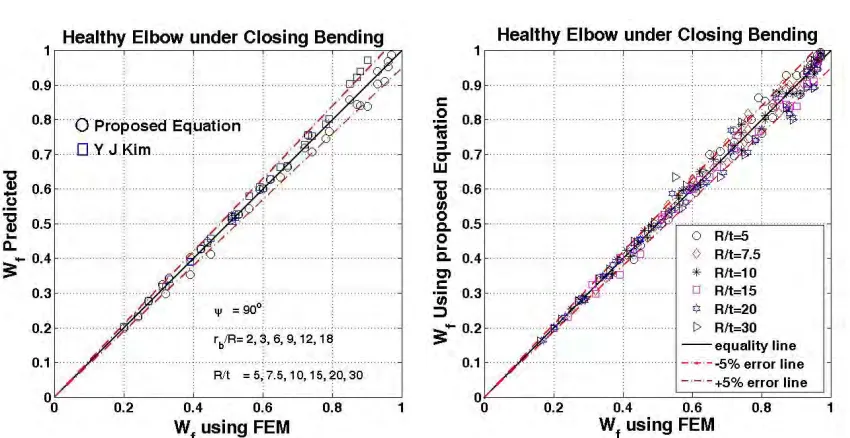
Fig. 4: Wf plot of (a) Predicted Vs FE evaluated for 90° elbow using the Kim, Eq.11 and new proposed Eq.18. (b) Predicted new proposed Eq.18 Vs FE for all ψ, rb/R and R/t
Figure 4(a) plot compares the predictions from the new equation with the Eq. 11 given by Kim [7] for elbows having ψ =90° and λ≤0.5. The two equations were found in good agreements except for cases with higher λ value. Comparison of prediction with many other literature equation was reported earlier Gupta [10]. Figure 4(b) plots the predictions using new Eq. vs Wf evaluated using FEM. This show that most of the data points lie within the ±5% error band.
R cracked elb factor is re crack angl shown in f and tabulat circumfere point wher angle shou Hence equ For thresho Th fitted as li investigate observed th typical R/t bellow. (a) Fig B constant D Fo above equa fitted linea trends. Fin elbow und Fi Chattopadh are very cl Eq. fails to equation re new Eq. vs
Results of the c bow subjected eported in tabl le (θth) below fig 5a for a typi
ted in table 4. ential crack ang
re this straight uld be zero as uation for the th old crack (θth)
he d1 and d2 w inear function ed with respect
hat the H(θ) ca , and rb/R case
H
) Typical H(θ) g. 5: Determina ased on the fa D1 and D2 are as
or each case, t ations for each arly as function nally close form er closing and igure 6(a) plot hayay [6] and M
ose and in goo o predict H(θ) easonability pr s H(θ) evaluate
crack weakenin d to closing/ope le-2 and also f which there is ical case. Henc To evaluate th gle and data p line cut the li maximum str hreshold value
equation is ass
were obtained a of R/t. The H t to the corresp an be a fitted a e. Hence a gen
for 1 ) (
Hθ = θ
Vs. θ variatio ation of crack w
ct that H (θ) ap ssumed to have
D
table-3, the co h of R/t and the n of R/t and b m equation for opening bendi t compares the Miller [8] for e od agreement w ) where bendi redicts for all c ed using FEM.
ng factor H(θ) ening bending flitted and giv s no effect of ce for each cas hreshold crack points are fitted ine H(θ)=1 is d ess point is on is assumed suc sumed to have
th
=
θ
as function of H(θ) variation ponding pipe’s as a second ord neral equation o
and th θ ≤ θ
on for an elbow weakening fact pproaches to h e functional for
( ) [ / 1 1 R rb
e
a
D
=
−onstant D1 and e constant a1 , a b1, b2 were fitt r the crack we ing, have been e predictions f elbows having with both new a ng radius is la cases and meet This show tha
have been giv moment, whil en by Eq.18.
crack on the p e of geometry
angle for give d in single line designated as n the extreme ch that it shoul functional form
( )
[ ( / 2
1 d R rb
e
d
−=
R/t using eq.2 s, for crack s s crack weaklin der function of
of the form giv
(
1 D)
)(
Hθ = − 1
w (b) Ty
tor and thresho h (θ) as rb/R ap rms such that th
).b1]
D
2=
a
2d D2 were eval a2, b1 and b2 we ted using polyn eakening factor
developed and from the new R/t=10 and ψ and Eq. given arge and also ts the asympto at most of the d
ven in table 3 le the correspo
The H(θ) resu plastic collapse this threshold en geometry Fa
e as shown in threshold valu fiber which is ld approach to m as given belo
]
2
20 and table-4 izes larger tha ng factor that
h(θ) with zero ven bellow is c
)
h−D2h2 foypical Elbow H old circumferen pproaches infin hey approache
( )
[ / .2]
2 b R rb
e
− luated. Further ere obtained as nomial or exp r H(θ), for thr d is given in tabequation (tab =90°. The plo by Chattopadh does not mee otic trend. Figu data points lie w
for through-w onding elbow g
ults show that e load for giv value of crack actor H (θ) is p fig 5a and ang ue. Ideally for p
s not happenin zero as rb/R ap ow.
data. The d1 an an the thresho
is h(θ), as giv o intercept, as s considered for t
or θ>θth
H(θ) Vs. Pipe h ntial crack angl nity (i.e. elbow
s to 0 with incr
r data analysis s function of R/
onential fit de ough wall circ ble-5. le-5) with the ot show that res hayay. Howeve ets the asympt ure 6(b) plots t within the ±5%
wall circumferen geometry weak there is a thre en geometry a angle was eva plotted against gle correspond pipe threshold ng in case of e pproaches to in
nd d2 variation old crack (θth), ven by Eq. 4.
shown in fig 5b the analysis as
h(θ) variation le for elbows w approaches to
rease in λ or r
was carried o /t. Then a1 and epending on th cumferential cr
equations giv sults of rb/R=2 er, Chattopadha
otic trend. Th the predictions % error band.
ntially kening eshold as also aluated t semi-ding to d crack elbow. nfinity. (20) n were , were It was b for a s given
(21)
o pipe) rb/R.
(22) out for da2, are he data racked
Fo
⎢⎣ ⎡ = θth 0.025
⎜ ⎜ ⎝ ⎛ ⎜ ⎝ ⎛ = 0.006 D1 ⎜ ⎝ ⎛ = 0.32R D2
Fig. 6: Cr proposed e Fi Chattopadh Chattopadh equation re new Eq. vs
Fig. 7: Cra equation, C
Table-5: Pro
W or Closing Bending
⎢ ⎢ ⎣ ⎡ − ⎥⎦ ⎤ +0.72 Exp t R + ⎟ ⎠ ⎞ ⎜ ⎝ ⎛ ⎟ ⎠ ⎞ ⎝ ⎛ t R 0.32 -t R 2 ⎢ ⎣ ⎡− ⎟ ⎠ ⎞ −0.8 Exp 1 t
R
rack weakenin equation, Chatt igure 7(a) plot hayay [6] and hayay, Miller easonability pr s H(θ) evaluate
ack weakening Chattopadhayay
oposed Close fo for 1 ) ( Hθ =
Where, h=Co
g (Extrados throug
⎥ ⎥ ⎦ ⎤ ⎟ ⎠ ⎞ ⎜ ⎝ ⎛ λ 0.08
t R 8 . 0 ⎢ ⎣ ⎡ ⎜ ⎝ ⎛ ⎟ ⎟ ⎠ ⎞ + 0 R r Exp 0.32 b ⎥ ⎦ ⎤ R r 5 . b
ng factor, H(θ) topadhayay and
t compares the Miller [8] for provide lower redicts for all c ed using FEM.
g factor H(θ) f y and Miller (b
form Equation f and th θ ≤ θ 0.5Si ) 2 / ( os θ gh-wall crack) ⎥ ⎦ ⎤ ⎟ ⎠ ⎞ −0.17 t R 004 .
plots for Closi d Miller (b) H(
e predictions f r elbows havin r bound values cases and meet This show tha
for Opening Be b) H(θ) predict
for Elbow with
(
1 D)
) (
H θ = − 1
and ) in(θ ⎢⎣ ⎡ = θth 0
⎜⎜ ⎝ ⎛ = -D1 0 D2=
ing Bending (a (θ) predicted fr
from the new ng R/t=10 and s of H(θ) and ts the asympto at most of the d
ending (a) H(θ ted from new e
h Circumferent for h D h 2 2 − Crac Half = θ
For Opening Ben
⎥⎦ ⎤ +0.36 E t R 012 . 0 ⎟⎟ ⎠ ⎞ ⎟ ⎠ ⎞ ⎜ ⎝ ⎛ -0.35
t R 0.01
-0
a) H(θ) vs θ plo rom new equat
equation (tab d ψ =90°. The
does not mee otic trend. Figu data points lie w
θ) vs θ plots fo equation vs. H(
tial through wa th θ > θ Angle ck
nding (Intrados thr
⎢ ⎢ ⎣ ⎡ ⎟ ⎠ ⎞ ⎜ ⎝ ⎛ λ − 2 . 0 t R 4 . 0 Exp ⎢ ⎣ ⎡ Exp R r 0.2 - Exp b
ots for data eva tion Vs. H(θ) e
le-5) with the e plot show th ets the asympt ure 7(b) plots t within the ±5%
or data evaluat (θ) evaluated u
all crack rough-wall crack) ⎥ ⎥ ⎦ ⎤ ⎥ ⎦ ⎤ ⎟ ⎠ ⎞ ⎜ ⎝ ⎛− t R 1 . 0 p
aluated using F evaluated using
equations giv hat the Eq. giv totic trend. Th the predictions % error band.
CONCLUSION
The investigation has highlighted that equations available in literature for evaluation of plastic collapse load of an elbow have limited applicability and do not cover wide range of pipe bend radius ratios and bend angles which are used in power plant piping. These equations fail to represent asymptotic trend where the plastic collapse moment of an elbow approaches to that of pipe when the bend radius is increased keeping R/t constant or when the bend angle is decreased. Most of literature equation for Wf, are function of λ alone, however, the study involving large number of nonlinear finite element calculations, revealed that Wf also depends on rb/R, R/t and ψ. Based on the FE results, a new close form equation (Eq.18) has been developed, which is function of R/t, rb/R and bend angle ψ and also satisfies the asymptotic trend discussed earlier.
A crack weakening factor H(θ), defined as the ratio of plastic collapse load of cracked elbow to plastic collapse load of corresponding elbow with no crack, was also evaluated using FE analysis for large number of elbow geometries and crack sizes. The FE evaluated elbow H(θ) for both closing and opening bending, were studies in relation with corresponding pipe h(θ), along with its variation with R/t and rb/R parameters. The H(θ) results revealed a threshold crack angle (θth) below which there is no effect of presence of crack on the plastic collapse load of elbow, i.e. H(θ)=1. The θth was evaluated for each of the geometry case and an equation (approach to zero as rb/R approaches to infinity) was fitted for θth. Further an close form equation was developed for H(θ) which reduces to h(θ) when rb/R increase and so satisfies asymptotic trend.
The plastic collapse load of an elbow without or with crack (circumferential) and under closing or opening bending can be obtained from corresponding pipe collapse load by multiplying it with a geometric weakening factor Wf and a crack weakening factors H(θ). The FE evaluated database as well as close form equations for the Wf and H(θ) have been presented.
REFERENCES
[1] Spence, J. and Findley, G. E. (1976). “Limit load for pipe bend s under in-plane bending” Proc.,2nd International Conference on Pressure Vessel Technology, San Antonio, Texas, 393-399
[2] ASME, Boiler and Pressure Vessel Code, Section III, Subsection NB, 2004
[3] Caladine, C. R. (1974) “Limit analysis of curved tubes”, J. Mech. Eng. Sci. vol 16, 85-87
[4] Goodal I. W., “Large Deformation in Plastically Deforming Curved Tubes Subjected to In-Plane Bending” Reserch division report, RD/B/N4312. Central Electricity Generating Board, UK, 1978
[5] Touboul, F. et. al. (1989) “Design criteria for piping component against plastic collapse: Application to pipe
bend experiments”, Proc.,6th International Conference on Pressure Vessel Technology, Beijing, China,73‐
84
[6] Chattopadahya, J. et. al. (2004) “Closed form collapse moment equation of through wall circumferentially
cracked elbows subjected to in‐plane bending moment” ASME J. of Pressure Vessel Technology, vol.126,
307‐317.
[7] Kim, Y. J. and Chang, S. O. (2006). “Closed form plastic collapse loads of pipe bends under combined
pressure and in‐plane bending”, J. Engineering fracture Mechanics, vol.‐73, issue‐11, pg.1437‐1454
[8] Miller, A. G., 1988, ‘‘Review of Limit Loads of Structures Containing Defects,’’ Int. J. Pressure Vessels
Piping, 32, pp. 197–327.
[9] Zahoor, A., 1991, Ductile Fracture Handbook, Vol. 3, EPRI‐NP‐6301‐D,N14‐1, Research Project 1757–69,
Electric Power Research Institute, Palo Alto, CA.
[10]Suneel K. Gupta, Vivek Bhasin, K.K. Vaze, A.K. Ghosh and H.S. Kushwaha, “General Limit Load and B2
Stress Index Equation for Pipe Bends under In Plane Bending”, 19th Conference on Structural Mechanics