Modified Extended Composite Right/Left-Handed Layout Loaded
with CSRR for Quad Band Applications
Parya Fathi1, Zahra Altasbaf2, *, and Keyvan Forooraghi2
Abstract—This paper presents the design and implementation of a novel fully planar modified, extended composite right/left-handed transmission lines (E-CRLH-TLs) utilizing a complementary split ring resonator (CSRR) loaded on the ground plane. The multiband behavior of the proposed layout is demonstrated by an equivalent circuit which in this case is distinct from the standard form of the equivalent circuits presented for an E-CTLH-TL; therefore, in order to design a quad band E-CRLH unit-cell, the design procedure is investigated. The main advantages of the proposed layout over other topologies are size reduction and fabrication simplicity which are proved by the design and fabrication of a quad-band Y power divider.
1. INTRODUCTION
As most of the networks are changing to operate at more than one frequency band, dual and multiband microwave components are required for implementation of such networks. Composite right/left-handed transmission lines (CRLH-TLs) introduced by Caloz et al. [1] recommended an attractive method for developing dual-band components since they have one right- and one left-handed propagation bands. Using this kind of transmission lines, numerous dual-band structures have been deigned in [2–7]. The Extended CRLH-TLs presented in [8, 9] are a generalized form of the CRLH-TLs proposed by combining conventional CRLH (C-CRLH) and dual CRLH transmission line introduced in [10]. E-CRLH-TLs have two more right/left-handed frequency bands due to owning two more resonators, and by engineering the impedance and dispersion characteristics, they can be utilized in developing dual- and quad-band devices as reported in [11–20].
Having two extra resonators in E-CRLH-TLs which add up four more reactive elements to equivalent circuit and equations, complicates the design and implementation procedure. Up to now, various layouts and design procedures have been proposed for implementing an E-CRLH structure. In [11], a quad-band Wilkinson power divider is fabricated in microstrip technology utilizing chip capacitors and inductors; however, in [18, 19, 21] quad-band Y power splitters and branch line coupler are implemented in a fully planar configuration using microstrip and SIW technology.
In this paper, a novel fully planar layout is proposed for the implementation of E-CRLH-TLs, and it is intended to reduce the size of the structure with the CSRR loaded on ground plane which operates as one of the four resonators of E-CRLH transmission lines. The equivalent circuit model of the presented layout is depicted in Fig. 1(c). This model is distinct from the conventional equivalent circuit of E-CRLH-TLs, but it exhibits alternated four right/left-handed bands. The feature is demonstrated by designing a quad-band impedance inverter which is utilized in developing a quad-band power splitter.
The paper is organized as follows. In Section 2, the topology and the modified equivalent circuit are demonstrated, and the design procedure is described. Section 3 presents the design and simulation of a quad-band impedance inverter. In Section 4, the quad-band impedance inverter is used to develop
Received 4 March 2016, Accepted 11 May 2016, Scheduled 6 June 2016
* Corresponding author: Zahra Atlasbaf ([email protected]).
1 Faculty of Electrical and Computer Engineering, Tabriat Modares University, Tehran, Iran. 2 Faculty of Electrical and Computer
a quad-band power splitter, and the results are compared to previous works. Finally in Section 5, the paper ends with conclusions.
2. THE THEORY AND DESIGN PROCEDURE
The proposed layout and its lossless equivalent circuit designed to behave as a quad band impedance inverter is depicted in Fig. 1. Lhpand Chp are realized by an interdigital capacitor with a narrow strip
line parallel with it. Lhs and Chs are implemented by meander inducer and interdigital capacitor. Lvp
and Cvp are achieved by a stub connected to the ground by vias, and the CSRR etched on the ground plane realizes C,Cc and Lc.
(c)
(b)
DCRLH
(a)
Figure 1. The proposed topology for a modified E-CRLH-TL, (a) top view, (b) bottom view, (c) equivalent circuit. The unitcell dimensions are: a = 1.75 mm, b= 1.57 mm, c= 0.3 mm, d = 0.4 mm, ws= 0.2 mm,ls= 0.49 mm,Rext= 3.13 mm,wst= 0.52 mm,lst= 5 mm,lm1= 0.41 mm,lm2 = 3.9 mm, lm3 = 0.6 mm,lm4= 0.61 mm andD= 0.5 mm. The width of digits in central and two other capacitors are 0.26 mm and 0.265 mm respectively. The line width of meander line and all spacing in interdigital capacitor are 0.2 mm.
The first step in the design of a quad-band transmission line is to find the values of the lumped elements in the equivalent circuit. For this purpose, the propagation constant and characteristic impedance of the transmission line can be easily obtained by applying a periodic analysis, from which we have
βd = cos−1(A) (1)
ZB = ñB
A2−1 (2)
design equations, first of all the elements of the matrix should be obtained by multiplication ofABCD matrices of each part in equivalent unit cell, respectively, as given in
A B C D =
1 Zhs
0 1
1 0
Yvp 1
1 Zhp
0 1
1 0
Yvs 1
1 Zhp
0 1
1 0
Yvp 1
1 Zhs
0 1
(3)
Here Zhs,Yvp,Zhp and Y are
Zhs= 1
j2ωChs +jωLhs/2
Yvp= 2
jωLvp +jω2Cvp
Zhp=
2
jωLhp +jω2Chp −1
Yc =
1 jωC +
jωLc
1−ω2LcCc
−1
(4)
By defining X,Y and Z as:
X= 1 +ZhsYvp
Y = 1 +ZhpYvs
Z =Zhp(1 +ZhpYvs) +Zhp
(5)
A and B elements of the matrix are obtained as
A=XY +ZhsYvs+YvpXZ+ZhsY Yvp
B=ZhsXY +Zhs2 Yvs+X2Z+XZhsY (6)
Now to design a quad-band impedance inverter we have to setβdequal to 90 degree andZB equal
to impedance of line at four arbitrary design frequencies, which leads to eight nonlinear equations with nine unknowns as
π/2 = cos−1(Ai) ZB = ±Bi
A2i −1
(i= 1,2,3,4) (7)
These equations can be easily solved using genetic optimization algorithm in Matlab, and the elements’ values can be determined clearly.
After finding the elements’ values for the desired design, the next step is to calculate the first tentative layout dimensions by means of parameter extraction. To do this, each part is simulated separately, and their parameters are extracted using the method presented in [22] for CSRR and the procedure demonstrated in [23] for other parts. The last step is to do an optimization in order to take into considerations the parasitic effects and find the final dimensions.
3. A QUAD BAND IMPEDANCE INVERTER
In this section, the procedure is applied to the design of a quad-band impedance inverter by means of one cell of the E-CRLH transmission line. The characteristic impedance is set toZB= 35.35 Ω, and the
four operative frequencies are chosen as f1 =2.4 GHz, f2 = 3.6 GHz, f3 = 5.1 GHz and 5.7 GHz. The elements’ values that meet the requirements obtained by solving the equations are: Lhs = 6.039 nH,
(b) (a)
Figure 2. Simulated frequency response of a quad band impedance inverter. (a) Phase of S21, (b) magnitude of S11 andS21.
confirms that the required±90 degree phase shift is obtained at each design frequency, and the E-CRLH cell behaves as a quad-bandλ/4 transmission line. This can be utilized to realize the microwave devices such as couplers and dividers in whichλ/4 transmission lines are the key components. The magnitude ofS11 shown in Fig. 2(b) is below−12 dB at four operative frequencies, which confirms good matching level.
4. QUAD-BAND POWER DIVIDER
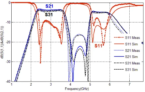
To show the quad-band feature of the designed impedance inverter, in this section, a quad-band Y power divider is implemented simply by adding two 50 Ω transmission lines to the output ports and exciting the input port by an extra 50 Ω transmission line. Photographs of the fabricated device are shown in Fig. 3, and the S parameter response of the power divider obtained from measurements is depicted in Fig. 4. For comparison, the results obtained from electromagnetic simulations are also included. There is good agreement between simulated and measured results, and the reason for the slight discrepancies is related to fabrication tolerance. It should be noted that the resonant feature of the structure makes frequency responses sensitive to geometric dimensions so that the acceptable tolerance for the final
(b) (a)
layout of the power divider is about 5 microns. The measuredS11, which represents the matching level, is better than 10 dB at four operative bands. The fractional bandwidths of 9%, 16.4%, 0.7% and 6.7% are achieved, respectively at first, second, third and fourth frequency bands. Moreover, the S21 losses for the four bands are 4 dB, 3.9 dB, 4.9 dB and 4.9 dB, respectively.
Figure 4. Simulated and measuredS parameters of a quad band Y power divider.
The size of the structure, excluding the access line, is 8.27 mm×7.33 mm which corresponds to 0.07λ01 ×0.06λ01 and λg1/8/5×λg1/9/85 (λ01 and λg1 are respectively the free space and guided wavelength at the lowest frequency band), and the advantage of the layout is due to implementing the DCRLH part of the equivalent circuit with a singleLhp/Chp resonator and CSRR resonator etched on the ground plane, which decreases the size and complexity of structure.
5. CONCLUSIONS
To decrease the size and complexity of an E-CRLH transmission line, a novel layout using a CSRR resonator loaded on the ground plane is introduced for the first time. The equivalent circuit which is different from the conventional form of an E-CRLH transmission line is derived for the proposed layout, and the procedure to design a quad-band impedance inverter is presented. To show the quad-band functionality of the proposed design a quad-band Y power divider is designed and fabricated, and there is a good agreement between simulated and measured results.
REFERENCES
1. Caloz, C., A. Sanada, and T. Itoh, “Microwave circuits based on negative refractive index material structures,”33rd Eur. Microw. Conf., 2003, 2003.
2. Sis´o, G., J. Bonache, F. Mart´ın, G. Cimitec, E. Electr`onica, and U. Aut`onoma, “Dual-band Y-junction power dividers implemented through artificial lines based on complementary resonators,”
2008 IEEE MTT-S International Microwave Symposium Digest, No. 1, 663–666, 2008.
3. Zhang, H. L., B. J. Hu, and X. Y. Zhang, “Compact equal and unequal dual-frequency power dividers based on composite right-/left-handed transmission lines,” IEEE Trans. Ind. Electron., Vol. 59, No. 9, 3464–3472, 2012.
4. Xu, H.-X., G.-M. Wang, and J.-G. Liang, “Novel CRLH TL metamaterial and compact microstrip branch-line coupler application,”Progress In Electromagnetics Research C, Vol. 20, 173–186, 2011. 5. Chi, P. and T.-Y. Chen, “Dual-band ring coupler based on the compos-ite right/left-handed folded substrate-integrated waveguide,” IEEE Microw.
Wirel. Components Lett., Vol. 24, No. 5, 330–332, 2014, [Online], available:
6. Jim, J. L., J. L. Jimenez-Martin, V. Gonzalez-Posadas, J. E. Gonzalez-Garcia, F. J. Arques-Orobon, L. E. Garcia-Munoz, and D. Segovia-Vargas, “Dual band high efficiency class CE power amplifier based on CRLH diplexer,”Progress In Electromagnetics Research, Vol. 97, 217–240, 2009.
7. Cao, W.-Q., B. Zhang, A. Liu, T. Yu, D. Guo, Y. Wei, and P. In, “Novel phase-shifting characteristic of CRLH TL and its application in the design of dual-band dual-mode dual-polarization antenna,”
Progress In Electromagnetics Research, Vol. 131, 375–390, 2012.
8. Rennings, A., S. Otto, J. Mosig, C. Caloz, and I. Wolff, “Extended composite right/left-handed (E-CRLH) metamaterial and its application as quadband quarter-wavelength transmission line,”
Asia-Pacific Microwave Conference, 2006, APMC 2006, 1405–1408, 2006.
9. Eleftheriades, G. V. and A. Abstract, “Generalized negative-refractive-index transmission-line (NRI-TL) metamaterial for dual-band and quad-band applications,” IEEE Microw. Wirel. Components Lett., Vol. 17, No. 6, 415–417, 2007.
10. Caloz, C., “Dual composite right/left-handed (D-CRLH) transmission line metamaterial,” IEEE Microw. Wirel. Components Lett., Vol. 16, No. 11, 585–587, 2006.
11. Papanastasiou, A. C., G. E. Georghiou, and G. V. Eleftheriades, “A quad-band Wilkinson power divider using generalized NRI transmission lines,”IEEE Microw. Wirel. Components Lett., Vol. 18, No. 8, 521–523, 2008.
12. Qiang, L., H. Lu, W. Zhao, J.-K. Wang, B. Liu, and P. In, “Simplified extended composite right/left-handed transmission line structure for dual-band applications,” Progress In Electromagnetics Research Letters, Vol. 15, 137–144, 2010.
13. Ryan, C. G. M. and G. V. Eleftheriades, “Design of a printed dual-band coupled-line coupler with generalised negative-refractive index transmission lines,”IET Microwaves, Antennas Propag., Vol. 6, No. 6, 705, 2012.
14. Ryan, C. G. M. and G. V. Eleftheriades, “A dual-band leaky-wave antenna based on generalized negative-refractive-index transmission-lines,” 2010 IEEE Antennas and Propagation Society International Symposium (APSURSI), 1–4, 2010.
15. Studniberg, M. and G. V. Eleftheriades, “A dual-band bandpass filter based on generalized negative-refractive-index transmission-lines,” IEEE Microw. Wirel. Components Lett., Vol. 19, No. 1, 2009–2011, 2009.
16. Chen, B. H., Y. N. Zhang, D. Wu, B. H. Chen, Y. N. Zhang, D. Wu, and K. Seo, “Novel composite right/left-handed transmission line for quad-band applications,”11th IEEE Singapore International Conference on Communication Systems, 2008, ICCS 2008, No. 4, 617–620, 2008.
17. Lakhtakia, A., L. Qiang, Y. Zhao, W. Zhao, Q. Sun, and B. Liu, “Extended dual composite right/left-handed transmission line,” Microw. Opt. Technol. Lett., Vol. 52, No. 12, 2838–2840, 2010, [Online], available: http://arxiv.org/abs/physics/0604155.
18. Duran-Sindreu, M., G. Siso, J. Bonache, and F. Martin, “Planar multi-band microwave components based on the generalized composite right/left handed transmission line concept,” IEEE Trans. Microw. Theory Tech., Vol. 58, No. 12, 3882–3891, Part 2, 2010.
19. Duran-Sindreu, M., J. Bonache, F. Martin, and T. Itoh, “Novel fully-planar extended-composite right/left handed transmission line based on substrate integrated waveguide for multi-band applications,” 2012 42nd European Microwave Conference (EuMC), 578–581, 2012.
20. Studniberg, M. and G. V. Eleftheriades, “Physical implementation of a generalized NRI-TL medium for quad-band applications,” European Microwave Conference, 2007, 408–411, October 2007. 21. Duran-Sindreu, M., J. Bonache, F. Martin, T. Itoh, P. B. Structures, and P. Components,
“Single-layer fully-planar extended-composite right-/left-handed transmission lines based on substrate integrated waveguides for dual-band and quad-band applications,”Int. J. Microw. Wirel. Technol., Vol. 5, No. 3, 213–220, 2013.
22. Bonache, J., M. Gil, I. Gil, J. Garcia-Garcia, and F. Martin, “On the electrical characteristics of complementary metamaterial resonators,”IEEE Microw. Wirel. Components Lett., Vol. 16, No. 10, 543–545, 2006.