PÉÍWS
w
E U R 4 4 1 5 e
pliiiåpiifli
i i Ærø
ÏW lift'
EUROPEAN ATOMIC ENERGY COMMUNITY - EURATOM
,. ML
¡»ϊίΛΗΤί
FOR DETERMINATION OF
| l i i i |
:CONVERTIBLE NUCLEAR HEATING DATA
>3>
H. KROCKEL
P w f e ' ï f t i
%:
u
ΜΦΜί »Bli
lliii
ι I
»?ΑΜί·
:
Mli*
m
d.i
l u " « " « s'.jifft »1/ ««iîiLitLlîi'
M. m fwämA.
i!fi\ »i».
ira?
μμμ)prψΜ ftw ·►:!?; «-futa u I«M ;LI l *î W M a?«* κ
k?»3w: Ά{'ί Λ nifi
ii
^f4 t* ír* K I*■** iuebsiiTïuUISenViívMi* 'vii ΝΉί
m
This document was prepared of the European Communities.
LEGAL NOTICE
RIEM
pared under the sponsorship of the Commission
mÍtíesSM
|l»lii'ií£M
fill
AU
if
m
lÉISIll*«
■'•riliiiftfftru
make any warranty or representation, express or implied, with to the accuracy, completeness or usefulness of the information tained in this document, or that the use of any information, apparatus, method or process disclosed in this document may not infringe privately owned rights; or
EUR 4415 e
A METHOD FOR DETERMINATION OF CONVERTIBLE NUCLEAR H E A T I N G DATA, by H. KRÖCKEL
European Atomic Energy Community - EURATOM
Joint Nuclear Research Center - Petten Establishment (Netherlands) Luxembourg, April 1970 - 44 Pages - 7 Figures - FB 60
The nuclear heat generation process is analyzed and presented in well-known form as function of the neutron and gamma energy distributions.
The energy distributions are approximated by expressions containing three unknown parameters which appear, after insertion, as three unknown linear constants in the heating equation.
By setting up this equation for three different materials, a system of three inear equations is obtained, the coefficients of which are computable functions. The solution of this system is presented in terms of experimentally determined nuclear heating values of the three materials.
The known solution can be used for calculation of nuclear heating data for any desired sample size and material by the same linear expression.
EUR 4415 e
A METHOD FOR DETERMINATION O F CONVERTIBLE NUCLEAR H E A T I N G DATA, by H. KRÖCKEL
European Atomic Energy Community - EURATOM
Joint Nuclear Research Center - Petten Establishment (Netherlands) Luxembourg, April 1070 - 44 Pages - 7 Figures - FB 60
The nuclear heat generation process is analyzed and presented in well-known form as function of the neutron and gamma energy distributions.
The energy distributions are approximated by expressions containing three unknown parameters which appear, after insertion, as three unknown linear constants in the heating equation.
By setting up this equation for three different materials, a system of three linear equations is obtained, the coefficients of which are computable functions. The solution of this system is presented in terms of experimentally determined nuclear heating values of the three materials.
The known solution can be used for calculation of nuclear heating data for any desired sample size and material by the same linear expression.
EUR 4415 e
A METHOD FOR DETERMINATION OF CONVERTIBLE NUCLEAR HEATING DATA, by H. KRÖCKEL
European Atomic Energy Community - EURATOM
Joint Nuclear Research Center - Petten Establishment (Netherlands) Luxembourg, April 1970 - 44 Pages - 7 Figures - FB 60
The nuclear heat generation process is analyzed and presented in well-known form as function of the neutron and gamma energy distributions.
The energy distributions are approximated by expressions containing three unknown parameters which appear, after insertion, as three unknown linear constants in the heating equation.
By setting up this equation for three different materials, a system of three linear equations is obtained, the coefficients of which are computable functions. The solution of this system is presented in terms of experimentally determined nuclear heating values of the three materials.
Numerical coefficients of this expression are given for materials C, Be, Mo and Fe as function of sample size.
A test rig, CADO-17 for measurements in the High Flux Reactor (HFR) at Petten is described; the chosen sample materials are C, Be and Mo.
Numerical coefficients of this expression are given for materials C, Be, Mo and Fe as function of sample size.
A test rig, CADO-17 for measurements in the High Flux Reactor (HFR) at Petten is described; the chosen sample materials are C, Be and Mo.
Numerical coefficients of this expression are given for materials C, Be, Mo and Fe as function of sample size.
E U R 4 4 1 S
e
EUROPEAN ATOMIC ENERGY COMMUNITY - EURATOM
A METHOD FOR DETERMINATION OF
CONVERTIBLE NUCLEAR HEATING DATA
by
H. KRÖCKEL
1970
A B S T R A C T S
The nuclear heat generation process is analyzed and presented in well-known form as function of the neutron and gamma energy distributions.
The energy distributions are approximated by expressions containing three unknown parameters which appear, after insertion, as three unknown linear constants in the heating equation.
By setting up this equation for three different materials, a system of three linear equations is obtained, the coefficients of which are computable functions. The solution of this system is presented in terms of experimentally determined nuclear heating values of the three materials.
The known solution can be used for calculation of nuclear heating data for any desired sample size and material by the same linear expression.
Numerical coefficients of this expression are given for materials C, Be, Mo and Fe as function of sample size.
A test rig, CADO-17 for measurements in the High Flux Reactor (HFR) at Petten is described; the chosen sample materials are C, Be and Mo.
KEYWORDS
HEATING GRAPHITE GAMMA RADIATION BERYLLIUM
NEUTRONS MOLYBDENUM NUMERICALS IRON
CONTENTS
1 . Introduci ion
2. Synthesis of Nuclear Heat Generation
2.1. Heat Generation by Core Gamma Radiation Ρ
2.2. Heat Generation Due to Core Neutron Radiation Ρ
η
2.2.1. Heat Generation by Elastic Scattering Ρ
J ■ n n
2.2.2. Heat Generation by Capture Gamma Radiation Ρ
ηγ
2.2.3. Heat Generation by Inelastic Scattering Gamma Radiation Ρ .
J η ι γ
2.2.A. Heat Generation by Decay Radiation Ρ ,
J J ndecay
3. Energy Distributions of Gammas and Neutrons
3.1. Approximation of the Gamma Energy Distribution
3.2. Approximation of the Neutron Energy Distribution
4. Solution of the Heat Generation Equation
4.1. Insertion of Gamma and Neutron Energy Distributions
4.2. Presentation of Heating as Linear Expression with 3
Unknown Constants
4.3. Determination of Unknowns Å , Β and C
o o o
5. Experimental
5.1. Principle
5.2. Sample Materials
5.3. Test Rig
5.4. Calibration and Sensitivity
5.5. Accuracy
6. Numerical Calculations
6.1. Expressions G, F and Ν
6.2. Determinant D for CADO17 c
7. Definition of Symbols
8. References
A METHOD FOR DETERMINATION OF CONVERTIBLE NUCLEAR HEATING DATA '
1.0. INTRODUCTION
-Calculation of nuclear heat generation in non-fuel materials of the High Flux Reactor (HFR) at Petten is in general
based on measured values, which are obtained by special calorimeter probes.
Although the presently available data are in themselves ra-ther complete, ra-there exists a considerable lack of means to apply them to conditions, which are different from the test conditions .
Particular difficulties are encountered, if the data are to be converted to objects having other geometry, size or ma-terial as the test sample.
These difficulties arise, because the nuclear heat generat-ion, which is a result of several energy absorption proces-ses of gamma and neutron radiation, is measured by calori-metrie methods in integral form, which does not reveal the
contribution of the individual process.
Data conversion however requires the knowledge of the con-tribution of each absorption process to the overall effect.
The functional dependency of a process on the sample para-meters has the form of an energy integral of geometry and material dependent parameters, in which only the energy distributions (more correctly the "energy spectral densi-ties of the number fluxes") of neutron and gamma particles appear as unknowns.
If these energy distributions are known, then the proport-ionate contributions of the absorption processes can be determined, so that the conversion problem can be solved.
Since the gamma energy distribution, which is the more im-portant one of the two, is not known for the HFR, some con-version relations had earlier been derived on basis of an assumed distribution.
Although by this evaluation, useful
nu-merical results could be obtained, it is desirable to pro-ceed to a method, in which no explicit assumptions on the energy distributions are needed and which also covers the influence of the neutron radiation.
Such a method must necessarily be based on a detailed ana-lysis of the energy absorption processes involved and must be directed on determination of parameters, which are re-presentative for the gamma and neutron energy distributions existing in the reactor.
The method described here, is laid out for determination of 3 constants, 2 representing the gamma and 1 the neutron distribution.
The description of these distributions by expressions con-taining 2 resp. 1 parameters is, of course, very approx-imate and will only be satisfactory for investigations of nuclear heating and similar effects.
The experimental principle of this method follows in some lines that of ref. 1 , where 2 parameters are determined, which relate the gamma and neutron heating of a material
2.0. SYNTHESIS OF NUCLEAR HEAT GENERATION
The main effects contributing to nuclear heat generation in non-fuel materials in the HFR are the following :
1. Core gamma radiation absorption, Ρ Y
2. Core neutron elastic scattering energy degradation, Ρ 3. Thermal neutron capture induced gamma absorption, Ρ
nY
4. Inelastic scattering (fast neutron) induced gamma absorption, Ρ . ηΐγ
5. Activation product gamma and β absorption Ρ „
: .ndecay
There are other minor sources of heat generation, such as
effects of (n,ot) and (n,p) reactions and others, which are however neglected here.
The 5 above mentioned heat sources are not equally important, and some of them have negligible contribution for some materials. In all cases, the dominant role is played by Ργ.
The total effect is combined in the form :
Ρ = Ρ + Ρ (1)
γ η
Ρ = Ρ + Ρ + Ρ . + Ρ , (2) η ηη ηγ ηιγ ndecay
2.1. Heat Generation by Core Gamma Absorption Ρ
1
Ï
The heat generation at a point with the local coordinate r in a
sample due to gamma absorption is given in ref. 2 as :
Ρ
γ ί
Γ ) => T~
(E)'
N<
E'
r> ·
E dE<
3>
The spectral number flux density at r,N(E,r) is obtained from the undisturbed flux density Ν (E) by multiplication with a factor which is, according to ref. 3, equal to the escape probability p(r) from the same body for a homogeneous internal source distribution; if linear exponential attenuation is
N(E,r) = No(E) . p(r) <4)
The average escape probability is :
P
o= i ƒ p(r)dV
ν
The average heating is :
(5)
■ * J
Ρ (r)dV γ. E γ \ N(E,r)dVdE (6)
(7)
Herein :
±
) N(E,r)dV =
-γ
J p(r)dV = Ν Ρ
o o (8)
And finally :
uu
Yy J jo D ρ O o rρ o . Ε dE (9)
Alternative Derivation
This result can be derived in an alternative way on basis of
the total amount of incoming photons η (spectral) and the
fraction of collisions F^ :
(10)
CO
1 Í Va
Ρ o _L· \ -± . ρ . η EdE
γ pV J μ c o
In ref. 3 one finds the relation :
η = Ν . γ
o o 4 ( U )
and the definition of the average chord R , which represents
e av' e
the mean of all possible penetrations through a body :
9
Introduction of these terms in eq. (10) yields
f ya Fc
= I _in
-4
E d!
ρ o uR
i v H av
(13)
Eqs. (9) and (13) are equal if
F
o yR
av
(14)
The proof that relation (14) holds, is given in ref. 6
Since in eqs. (9) and, (13) the effect of secondary gammas
(scattering gammas) is neglected, these expressions give under
estimated values for Ρ , which are corrected by introduction
γ .
of the energy absorption buildup factor Β , which is applied
in the linear form proposed in ref. 4 :
Β (E,yr) = 1 + (f 1 ) yr (15)
With use of the mean value r = r R in eq. ( 1 5 ) , eq· (9) become s
ζ. a v 00
■ ! 1 + ^ ( _ 1 ) u R a v
a
ρ Ν EdE
1 o o (16)
The average escape probability ρ is a function of photon energy
and sample geometry. Calculations of ρ are rather extensive.
For simple geometries, tabulated results can be found in ref. 3 ;
among them are tables for slabs, spheres, halfspheres and
infinitely long cylinders.
The result for infinite cylinders is reproduced in fig. 1. It
can also be used with good accuracy for length to diameter
ratios L/D >0.5, if one replaces χ by the parameter :
X = \ w Ra v '
10
where R , defined by eq. (12), is for cylinders
R
a V l^D/L
Definition (17) permits the shorter form of eq. (16) :
(18)
Ρ = γ
1 + < — ! ) ρ (Υ).N .E.dE
ro Λ o (19)
Other geometries than cylinders can be treated in analogue form
on the basis of ref. 3.
2.2. Heat Generation due to Core Neutron Radiation Ρ
2.2.1. Heat Generation by Elastic Scattering Ρ nn
In ref. 2 the following expression is given for neutron
heating by elastic scattering :
00
Ρ (r) =
nn ^ ( E ) . Ρ Σ (E) 0 (E,r) dE, s
(20)
where the mean energy degradation per collision ΔΕ is :
ΔΕ = E . 2A
(A+l)
(21)
Analogue to sect. 2.1., the local flux density can be
expressed by the undisturbed flux density and a pro
bability. The volume average has the form :
00
11
w h e r e i n t h i s e q u a t i o n
2E T R
( 2 3 )
av
and ρ (χ) is taken from fig. 1, R corresponding to eq. (13)
Graphs of Σ and £„, are presented in ref. 4 .
s ι
2.2.2. Heat Generation by Capture Gamma Radiation Ρ S*
For the (η,γ) reaction following thermal neutron capture is
assumed, that it has a spatial distribution in the sample
producing a homogeneous gamma source distribution.
Under this condition the heating due to capture gammas can be
expressed by
= - . Σ .φ „. . ρ ( Y ) . Β — . ρ ( χ ) · q ( Ε ) . Ε d]
η γ p a Yo t h ro Λη J a y c A η γ (24)
where
oth 0 (E)dE o (25)
'th
is the thermal neutron flux density. The build up factor Β is
a
Β = 1 + (_ÍL1 ) . χ
a y ' Λ
a (26)
In view of the information available in ref. 2 , the integral
can better be expressed as a sum over discrete energy intervals
ΔΕ. i n t h e f o r m :
Χγ Ν
( β ™ · Ρ ( χ ) . q ( E ) . E d E * ) — ( Ε . ) . Ρ ( v ) . E . j jaf q dE ( 2 7 )
J a y c Λ ^ η γ / μ ι . ^ c λ ι öa J Ηηγ ν '
12
In this expression, ρ (χ) is the collision probability
Pc(x) = 1P0(X) , (28)
In the preceding equations, χ is defined by eq. 17 and γ by
I r ρ ( 2 9 )
Xn " 2 V n T av'
The integrals
; q ηγ (E.)dE = S(E.) i i (30)
ΔΕ . ι
are tabulated in ref. 2 for 7 gamma energy intervals and for
all important materials. Eq. (24) can therefore be written :
Ìo t h Po( Xn) ' ¿ a " (Ei).Pc(x).Ei.S(E.
Ρ
ηγ
=¿V
i=l
Ρ is in general negligible for materials having comparably
small absorption cross sections.
2.2.3. Heating by Fast Neutron Inelastic Scattering Gamma Radiation
Ρ .
_ηιγ_
In the few cases, where inelastic scattering (fast neutrons)
induced gamma radiation contributes to the heating, one can
treat the induced gammas as monoergetic with energy Ζ .
Under analogue conditions as in sect. 2.2.2, the heating gan
then be expressed as :
• Ε . Ι Σ .
γ J n i
-Β μ
Ρ . = — — (Ε ) . ρ ( χ ) . Ε . Ι Σ . (Ε ,Ε ) 0 (Ε ) ρ (x„ ) d E ,
η ι γ ρ μ γ * c Α γ / ηΐγ γ n o n/ j ro ΛΤ η '
13
where Β is defined by eq. 26. Furthermore
a
PC( X ) = ! _P0( X ) (33)
and
X = 2'j Rav (34)
XT = 2Σ TRav (35)
Cross section data are available in ref . 4 .
2.2.4. Heating by Activation Product Decay Rad ia tion. Pndecay
In some cases, thermal neutron capture generated nuclides
contribute to the heating by their decay gamma and beta
radiation .
For calculation, it is again assumed, that the gamma and beta
source distributions are homogeneous. The decay radiation
normally originates from a nuclide, which was generated by
neutron capture in an isotope, the natural abundance of which
in the material under consideration is y .
η
The source strength therefore is
y „ E •♦„fi, · ρΛ( χ „ )
n a o t n o η
(36)
If the decay gamma and beta energies are E and ER, the
partial heating term0 are :
Β y
a a
nde cayy = — ρ — y (Ε ).p (χ).Ε .y .Σ .φ . .ρ (χ ) γ lc γ η a oth *ο η (37)
14
where β is defined by eq. 26 and
Xn = I EthTRav ( 3 9 )
x =
1
^ V ^ a v
(40)x
e
- \
'
*
a'
Rav
<
4 , )The total decay radiation heating must be summed up from
the partial heating terms according to the decay characteristics
of the involved nuclides, so that
(42)
Ρ = Σ Ρ + Σ Ρ
ndecay ndecayy ndecayß
The relations derived above apply to equilibrium conditions,
which are reached only after a time of several half lives
15
-3.0 ENERGY DISTRIBUTIONS OF GAMMAS AND NEUTRONS
The three types of parameters of the preceding sections :
Attenuation coefficients or cross sections, Geometry averaged reaction probabilities, Particle energy distributions
are direct or indirect functions of particle energies; the
energy distributions of neutrons and gammas therefore constitute the key to heating calculations.
Energy distributions of neutron flux densities in the HFR are in general available by 4 group computer codes of the neutron metrology group (RCN) .
The -for heat calculations- more important gamma energy distributions are unknown in the operating reactor.
The calculations of gamma heating terms are therefore based on a double exponential approximation of the energy distribution with two unknown linear constants.
3.1 Approximation of the Gamma Energy Distribution
The gamma energy distribution of the operating reactor is a result of the interactions of the prompt fission spectrum and the fission product decay spectrum with the materials of the core region.
In general, this distribution is a rather complicated
function of the configuration and can only very summarily be expressed by a two parameter approximation.
In the higher energy region (E>lMeV) the prompt and fission product spectra show an exponential form, approximated in ref.
- 1 1 E . 5 by a function e . Other measurements, mentioned in ref. 5,
-1 . 24E which include also capture gammas, suggest a form e
2 8
Since in the present case Al decay will cause appreciable increases of a distribution in the range E<1.3, one can
- 16
-2 3E
In the range E<lMeV ref. 5 suggests e ' for the prompt gammas. However, a great contribution of degraded higher energy photons must be expected in this region, the actual spectrum can therefore be expected to have an exponent <-2.3. For convenience, -2.5 is chosen; the distribution is therefore approximated by the expression
» /Ί?Λ Α *s -1.25E _ Φ δ -2.50E , . , .
Ν E « A . ·τ- .e + B .·=— e (4.3) ο ο E ο E s s
The exponents - 1 .25 and -2.50 have the dimensions KeV , if E is taken Ln MeV. .
Φ3
The multiplication with ■=— is applied in order to make A and
fc-s °
Β non-dimensional, o
The gamma energy distribution could also be approximated by various other two parameter expressions, but in view of the presentation in ref. 5., the exponential form is preferred here.
3.2. Approximat ion o f the Neutron Energy Distribution
For the approximation of the neutron energy distributions, results of the TEDDI-KFR 4 group code are used as·, a basis. These results refer to the integrated energy spectral densities of the neutron flux in the form
ET T
(
Φη " I 0(E)dE , η = 1 . ..4 (44)
ELn
where the following energy limits are attributed to the group :
Φ] : E - 1 . 3 5 MeV ET J ] = 10 MeV
Φ2 : EL 2 = 6 7 . 4 keV Eu 2 - 1 . 3 5 MeV
Φ3 : EL 3 = 0.625 eV E = 67.4 keV
- 17
One can derive from the TEDDI results, that the group fluxes φ are roughly equally related to each other in all central positions and also, bun functionally slightly different, for peripheral positions of the HFR,
Th.es e two forms can be appro χ im? ted by :
Φ. η
Φ~7
; + 0 , 7 0 ('η - ί ) - 0 . 0 5 ( η - 1 ) 3 (45)Φ 1 + 0 .75(η-1) (46)
for central (4 5) and peripheral (4 6) positions, respectively. The characteristic'ratio
Φ. (47)
is by these approximations 1.51 for central positions and 0.85 for .peripheral positions.
For a given core position,, relation (45) or (46) can be used to approximate the neutron energy distribution in group representation by
'Un/
Ln
0 (E)dE » C o o n A,
Φ7
■
φ3'
(48)
where the factor φ is used for obtaining a non-dimensional form of s
18
4.0 SOLUTION OF TUE HEAT GENERATION EQUATION
·' 4.1. In sert ion of C a r. n a a n d Neu tron V. n c r g y Ώ i s t r i. b u t i o n s
The energy d i s t r i b u t i o n s of gammas and n e u t r o n s , represented by e q s . (43) and ( 4 8 ) , can now be applied to solve the various heat generation expressions of s e c t . 2 up to the u n k n o w n
factors A ,
o o o and C .
For this procedure the following insertions are made :
I) Eq. (43) in eq. (19) :
Ρ = A o'E l + (·— -l)x| .p„(x) .e
:]·«·.
1 .25E EdE (49)+ Β .--ο E ! + (—- -1)χ .ρ (χ) .e .EdE t . -2.50E _,_
II) Eq. .(48) in eq . (22) :
Eq. (22) is approximated by the sum :
2Λ
n n ( A+l )2 P
A
) .Σ . s
n=!
rUn
'Ln
0 (E).EdE o (50)
The integral of this expression can be solved by applying eq. (48) in the following form :
JUn
o n ETT
-Ε,-Un. Ln
C
0dE = ~ ~ 2
-o E„ - E
Φ.
n A
Un Ln ™1
( 5 1 )
19
w h i c h b r i n g s :
'Un
0 E d E = £ o E „ E Ln
.
~
.φ 4(E.
2. E
T2)=4c (Ε.. +E
T)·Αφ
φ, Ts 2 Un Ln 2 o Un Ln φ, s
Un L n 1 1
(5'2)
and
p c .
-JL-
1
nn o / ... χ 2
E
Φ .
Ρ (ΧΤ)'Σ0 (Ε..+Ε).. — . φο (5.3)
/ . . \ ¿ Ρ / ο Τ s Un Ln φ, s
( Α + , )
5=1
. *
III) Eq. (48) in eq. (31 ) :
The thermal neutron flux density φ ·.. corresponds to the 4th otn
energy group, and therefore :
Φ Λ
φ . , = C . —— . φ
oth ο φ. s (54)
Za φ4
Ρ = C . — . ¡ ^ .ρ ηγ o p Φ]
7
(Χ ) Λ Β3— ( Ε . ) . ρ (χ) .Ε. .S(E.) .φ ο Λη / a y χ ι' 'c ι ι ¡
i=l
(55)
IV) Eq. (48) in eq. (32) :
Eq..(32) is approximated by:
Ρ . -C — (Ε ) . ρ ( χ ) .E
η ι γ o y Y c
Γ 4
■ ■•Γ
m= 1
Σ . φ "' ., ι J
— , ν Λ ί γ m .
ο Τ ρ φ j s ( 5 6 )
V) Eq. ( 4 8 ) i n e q . ( 3 7 )
y Σ ψ,
Ρ · , - C — (Ε ) . ρ ( χ ) . Ε . ν . — . -r-ί-.φ ρ (χ ) Β
ndecayv ο μ γ lc γ ' η ρ φ. s1 ο η' D a
- 20
V I ) E q . ( 4 3 ) i n e q . ( 3 8 )
Σ φ.
P J rt=C.p(x„).E„.y. . -— .φ .ρ (χ )
n d e c a y β o l c A g ρ ' η ρ φ γs ' ο Λη
(58)
4.2. Presentation of He a ting as Linear Expression with 3 Unknown Constants
By summing up the terms of sect. 4.1. to the total heat generation (eq. 1), an expression for Ρ is obtained, in which the unknown factors A , Β and C appear in linear combination, o o o
r '
The resulting eciuation can be written:
Ρ » A . G + B . F + C . Ν o o o (59)
G, F and Ν are short forms of the following expressions
G »
ψ
Es ) ρ
o
i + (— - D x P0( x ) . e ' " - . E . d E - 1 "> S F ( 6 0 )
00
Ι
ν
τ
H
rv*--Dx
a
, . - 2 . 5 0 E „,_,
p ( x ) . e .EdE ( 6 1 )
N
(A
4
ΐ ' TT' 1 P I(X T )
+ 1 )
2
Ρ
¿_
° Τ
m= 1
Φ
m .Σ . (ETT +ET ) . ~ .φ
s Um Lm φ . Ts
Σ φ.
a τ4
Ρ » Φ £~ ·
7
Σ
" VaΒ — ( Ε . ) . ρ ( χ ) . Ε . . S ( E . )
a y ι *c. Α ι ι
i - 1
- 21
Β yn
+ — — (E ) .ρ (χ) .E p y γ c γ
4
m=l
Φ m
(χ
Τ>·
Σηίγ·
f¡'
φ 5¿Ι
μ Φ ΛΒ a y γ- c— (Ε ί.ρ (χ).Ε .y .Τ. .ρ (Υ ) ~ . φ
Α γ η a *ο Än φ vs
'η . decayy
(62)
ί-E
Φ,Ρ ο( χβ)·Εβ · ^ η -Ση · Ρ ο( χη)· φ~ ·φ 5
Ε η . decay β
For convenience, the different arguments of the probability factors are once more listed here :
■Õ y R
2 av
2 ΣΤ Ra v
(63)
η 2 Et h T Ra v
ß
1
2 μ ß av
The expressions G, F and N ( 6 0 ) , (61) and (62) are functions of
the sample material and the sample geometry and size; they can
be determined theoretically.
For cylinder geometries, which are considered here, the influence
of size is expressed by the dependency of G, F and N on R
The dimensions of G, F and N are the same as the dimension·of
22
4.3. Determination of Unknowns A , Β and C
o o o
The solution of eq. (59) for the total nuclear heat generation
now depends on the knowledge of the constants A , Β and C
'· o o O
of the gamma and neutron energy distributions.
A and Β are unknown; C can be obtained by the TEDDI code
o o ' o J
theoretically and by activation analysis experimentally; it
is however not advisable *·ο apply the sofound values, in view
of the complete loss of selfcorrection within the further
process.
It is therefore useful to consider all three constants as
unknown and to determine them simultaneously in a common
procedure.
For this purpose, the method applied in ref. I is used here
in a modified form. It- consiste in a measurement of the heat generation in 3 materials and solution of the system of 3
linear equations (59) with ¡the measured values P.
With the subscript* 1, 2 and 3 for the 3 materials, one has :
pi ;GiAo * FiBo *■ Mico
P2 V o * F2Bo * B2Co (64)
P3 * V o * F3Bo * V o
The determinant of the coefficients is :
ro,
F ,
1Q2 F, *2
C3 P3 H3
(65)
The solution can be presented in the following form :
1
23
-W 1 · I CN2G3-G2N3)P1 ♦ ( G1N3- N1G3) P2
C
N1G2 -G1N2 >P 3]
( 6 6 ) I tn τ, τ. „ ^ ,τ, n r* - N« ( G . F _ - F , G. ) Ρ .
o= Dc » ( G2F3 -F2G3) P1 + ( F1G3 -G1F3) P2 + * 2 ' 2 3
Once these constants have been determined, one can express
numerically the approximations for the gamma and neutron energy
distributions (43) and (48) for the conditions of the measurement
(core position, core configuration, etc.).
For the same conditions, the constants in combination with
eq. (59) permit to calculate the nuclear heat generation in
samples of any material, geometry and size, for which the
24
5.0. EXPERIMENTAL
5.1. Principle
The experimental determination of the constants A , Β and C
r o o o
according to sect. 4.3. requires simultaneous measurement of the specific power for 3 different materials, which are
exposed to the radiation at the same point of the reactor core. Since this is, in the strict sense, impossible, it is necessary to apply a separation in either time or space.
The principle of time separation requires use of calorimeters, which can be moved to the measurement position in succession.
The principle of space separation can be realized with fixed calorimeters.
In view of the rather slow changes in the radiation at a given point of the core, the time separation introduces practically no mistake, whereas the space separation can be subject to errors caused by local differences in the radiation pattern. These errors are difficult to estimate and can only be kept at a minumum by minimum spacing of the calorimeters.
The practical realization of the time separation principle (movable calorimeters) however, is rather difficult and intro duces special problems in view of the required sensitivity of
the calorimeters.
Since construction of rigs with movable probe supports is
presently an unproved technique for the HFR, preference is given to the somewhat less accurate solution with fixed calorimeters.
5.2. Sample Materials
25
In numerical terms, the determinant D (eq. 65) should approach a maximum value.
On the other hand, the sample materials should be suitable for construction of geometrically equal calorimeters with good sensitivity and limited temperatures, which is an important requirement reducing the risk of thermo-couple failures.
On the above basis,· the combination graphite-molybdenum-beryllium was chosen. Estimated heating ratios of these materials are
approximately :
Gammas : C : Mo : Be τ 10 : 14 : 9 Neutrons: C : Mo : Be * 1 : 0 : 2
The thermal characteristics of C and Be calorimeters are very similar, the temperatures in Mo are comparably high, due to Lhe higher heating rate and the greater density,
Cross sections and absorption coefficients are well known for all 3 materials; the specific heats and their temperature derivatives (source : ref. 6) as defined by.eq. (67) are listed in the
following table :
1 + q(T - T
o)j
(67)M a t e r i a l
Be C* Mo
ρ [ g / c m J.
1 .85 1 .69 10.21
co[ j / ( g d e g ) ]
1 .89 2 0 . 7 6 2 0 . 2 5 3
q [ l / d e g j
0 . 0 0 1 7 8 0 . 0 0 3 3 2 0.00026
To[ d e g C ]
35 35 35
T [deg C]
0<T<150 0<Τ<200 0<Τ<600
* graphite Carbone Lorraine type 3780 WEG
- 26
5.3. Test Rig
A test rig, which can be inserted into the relevant experi-mental core positions of the HFR, is designed on basis of
the principles of the CADO series, being in use at Petten.
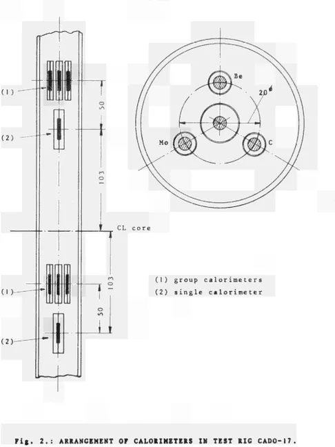
This test rig, CADO-17, is a carrier for isothermal calori-meters, which are arranged at the 4 vertical stations shown on the scheme of fig. 2: (1) two groups of 3 calorimeters
(referred to as "group calorimeters") with graphite, molyb-denum and beryllium samples and (2) two single calorimeters with graphite samples.
The group calorimeters have capsule diameters of 6 mm, the single ones of 10 mm. The single calorimeters serve for com-parison with earlier measurements, for which the same types had been used.
The calorimeter capsules are of stainless steel with a wall thickness of 0.3 mm; the free space is helium filled.
The group arrangement is shown in fig. 2 too. The center radius of 10 mm is a compromise between minimum spacing (see sect. 5.1.) and the distance needed in order to reduce mutual influencing
(shadowing) of the calorimeters.
The calorimeters are cooled by the primary coolant of the HFR, flowing in downward direction through the rig. The rig is in-serted in a standard filler element.
The inner and outer thermo-couples of each calorimeter are
connected in differential junction in the head of the rig.
The instrumentation is a Solartron digital data logger with
27
5.4. Calibration and Sensitivity
Calorimeters are calibrated outofpile by derivation of
the temperature dependent time constant of the differential
thermovoltage, developped in response to a sudden decrease
of the cooling temperature.
The first order approximation for this time constant reads
M = K ·(1+βΔΤ) (68)
With this, the differential equation of the calorimeter res
ponse
dAT dt
AT M
has the solution
AT
AT = exp M, + ß(AT AT) (69)
Measured response curves of CADO calorimeters are perfectly
represented by this relation, so that the parameters M0 and β,
defining M by eq. ( 6 8 ) , are easily determined from the measured
response on basis of eq . ( 6 9 ) .
A steady state calorimetrie measurement is evaluated, the time
constant being known, from the following equation:
p
="Fk
· π ·
ΔΤ (70)The correction factors f and k, allowing for the influence of
the inner thermocouple mass and heat capacity and the heat loss
by the sample supports, respectively, have been calculated;
- 28 Calorimeters type single group M II Samp le material C C Be Mo f 0 .985 0.985 0.975 1 .004 k 0.043 ' 0 .024
0.024 0 .024
The following table shows predicted mean values of the time W
constant, the temperature difference developped per /g of heat generation and the sensitivity of the calorimeters,
defined as the output in millivolts (thermo-voltage) per /g of heat generation.
Calori-meter type s ingle group group group sample mate-rial C C Be Mo capsule i . d.
29
5.5. Accuracy
According to an analysis made in connection with earlier experiments, the expected mean error of CADO measurements is of the order of 4%.
Since the same calor ime tei type is used for the present method, it is reasonable to consider this value also as the mean error of the individual calorimeter output.
The total error of the method, which is the error attributed to the final result A , Β , C , must be evaluated on basis of
o o o
eq. (66), in which the calorimeter outputs are combined with the elements of the determinant D (eq. 65).
The accuracy of these elements is rather difficult to estimate, because it depends very much on the unknown quality of the
approximations for the gamma and neutron energy distributions.
30
-6.0. NUMERICAL CALCULATIONS
6.1. Expressions G, F and N
The expressions G, F and N of eq. (59), which are formulated in eqs. (60), (61) and (62), have been evaluated for the mat eri als
C, Be, Mo, Fe
and for cylinders of the dimensions
0 < R < 6 cm. av
-Eqs. (60) and (61) were integrated graphically by means of a planimeter, with upper integration limits of 8 MeV for G and 4 MeV for F.
Absorption coefficients were taken from refs . 5, 7 and 8.
N has been determined on basis of the mean of the neutron group energy distributions (45) and (46), reading
Φ
— = 1 + 0.70 (η - 1) - 0.03 (η - Ι )3 (71)
Φ1
Cross sections were taken from ref. 4.
The n»Y contributions were evaluated on basis of the 7 group capture gamma spectra of ref. 2.
Numerical results are presented for the standard values of
E = 0 . 1 MeV s
φ = 1 0 cm sec s
31
It should be noted, that numerical values of A , Β and C , o o o which are obtained experimentally and by inversion of the
linear system (64), are only valid for parameters G, F and Ν with the above mentioned standard values of E and φ .
s s 6.2. Determinant D for CADO-17
c
The samples installed in experiment CADO-17 are cylinders of 3.2 mm diameter and 20 mm length; their corresponding value of R (eq. 18) is av
R = 0 .296 cm av
The determinant (65) is set up by coefficients G, F and N, which are read from figs. 3 through 5 for this R . The in
av correlation used here is 1 for C, 2 for Mo, 3 for Be :
D = c
2 . 6 6 7 3 . 4 9 1 2 . 3 2 0
0.757 1 .443 0.644
The value of D is : c
D = + 2.143 W3 g"3
c °
I .470 0.240 3.110
(72)
(73)
On basis of this figure, eqs. (66) are evaluated to (P in Watts/gram) :
A = + 2.022 P„ - 0.657 P„ - 0.905 PD
o C Mo Be Β - - 4.806 Pn + 2.279 P„ + 2.096 P_
o C Mo Be C = - 0.513 P„ + 0.018 P„ + 0.563 P_ , o C Mo Be (74)
where the indices C, Mo and Be stand for the corresponding materials.
Since physically meaningful solutions require that Ρ > 0 and Ρ > 0, there exist the conditions
γ η
-A G + Β F > 0
o o
-C > 0
o
- 32
By insertion of eqs. (74) into (75) and use of values G and F of (72), one finds a field of physically meaningful specific power ratios, which is shown in fig. 7 as the area limited by the straight lines (a), (b) and (c) .
However, in view of the expected gamma energy distribution, only a part of this field can be realistic.
The actual gamma distribution of the HFR has in all probability a form, to which both terms of approximation (43) contribute with positive sign, so that the expected field of solutions has the sharper limits
A > 0, Β > 0, C > 0 . (76) o o ' o
-This field is, on basis of eqs. (74), the triangle I-II-III (fig. 7 ) , in which point I corresponds to a gamma energy
— 125E — 2 50E distribution type e (hard spectrum), point II to e
(soft spectrum) and point III to pure neutron energies.
Accordingly, on a line connecting two points, the contribution represented by the opposite point is zero.
It can be expected, that actual HFR results will fall close to the line I-II, because the neutron effects are relatively small.
The results of measurements at different points of the core combine to a curve or a field, the magnitude of which depends on the variation of the spectra over the core.
ACKNOWLEDGEMENT
33
7.0. DEFINITION OF SYMBOLS
A a tomic we igh t
A ,B ,C constants of energy distributions, eqs. (43)
Ο Ο Ο > -ι - '
and (48)
B energy absorption build-up factor
D diameter
D determinant of coefficients, eqs. (65)
E energy of gammas and neutrons
E standard energy, arbitrary definition
F defined by eq. (61) F fraction of collisions c
G defined by eq. (60)
L length of cylinder
M time cons tant
N defined by eq. (62)
N energy spectral density of gamma number flux (eqs . 3 ... 8)
N energy sp. dens, of gamma number flux, undisturbed
Ρ specific power of nuclear heating
R average chord
av b
S total surface of sample
S(E.) integrated capture gamma spectrum, defined by eq. (30)
Τ temperature Τ reference temperature o
r
ΔΤ temperature difference corresponding to U
U„ differential thermo-voltage of calorimeter
34
c specific heat
c reference value of specific heat o
f correction factor
k correction factor
n total amount of photons coming in
O f b
ρ escape probability
ρ volume average of ρ
ρ volume average of collision probability, eq. (28)
q temperature derivative of specific heat
q energy spectral density of capture gammas produced per capture
r local coordinate
y natural abundance 'n
Σ absorption cross section a
r
Σ scattering cross section s
6
Σ„ total cross section
Σ,, „ total cross section for thermal neutrons t h 1
E . cross section for inelastic scattering gamma ηιγ e & ray production
0 energy spectral density of neutron number flux
0 energy spectral density of neutron number flux, undis turbed
μ gamma ray attenuation coefficient
u gamma ray energy absorption coefficient 3.
μ„ beta ray absorption coefficient
Ρ
σ
density
- 35
oth
n
neutron number flux
neutron number flux, undisturbed
undisturbed thermal neutron number flux
standard neutron flux, arbitrary definition
neutron number flux in energy group n, eq. (44)
defined by eqs. (63)
defined by eqs. (63)
defined by eqs. (63)
36
-REFERENCES
j_lj H.J. Leyers
Die Neutronen- und Gamma-Aufheizung in Experimentierkanälen des Reaktors FRJ2. Jül-351-RX Juli 1965.
[2\ E.P. Blizard (editor)
n d
Reactor Handbook, 2' edition Volume III Part B: Shielding
Intersci. Pubi., 1962.
p ] Case, Hoffmann, Placzek
Introduction to the theory of neutron diffusion Volume I.
Los Alamos Scientific Lab, June 1953.
(_4J Hughes, Schwartz
Neutron Cross Sections.
BNL 325, 2n d edition, July 1958
[f\ H. Goldstein
Fundamental aspects of reactor shielding Addison-Wesley Pubi. Comp. Inc., 1959.
(_6J Landolt-Börns tein
Kalorische Zustandgrössen .
Band II, 4. Teil Springer, 1961.
[7] US AE C
Reactor Physics Constants
37
[β] C.M. D avi s s on
Gamma Ray Attenuation Coefficients Append ix 1 o f :
Alpha-, Beta- and Gamma-Ray Spectroscopy Vol . 1 ,
O.Ol 0.02 0.05 O . I O .2 O .5 10
2'X for χ>10
Ρ - 1 - TX for x<0.01 ο ό
39
-CL core
[image:43.595.60.547.61.710.2](1) group calorimeters (2) single calorimeter
40
w / g
! ! I : I ' ! ; 1 ] ! '
, , ι 1 1 M i l
— —
l i ' i ' ' . ; | ' 1
; ' ■ * " i ' ¡ ! ' | | |
■ ■
ι ;
1 1 1 1 ¡ M ' Ι ι ! ι t ! ι i I l M M M M !
1 ' _ L L L * M Φ
M ! Τ "¡ ' 11 I
1
1 1
! 1
!
| | ■ j | ; ι | | ι | ι ι ■ ■ " " " "t " I I " I I I [
i I I ' l l ! j I 1 ; l ' l ' " ' j | | | | | | ι ,
| : ι ι ι ' i ι j
i i
N ' ! ' ! ' : ! ι 1 ! | ι :
:
I
! M ! 1 ! ! M l
I
1 ¡ ! ' ' ■ ! '
^L
M * s ^ " S^ ; "
^FÇT" ^ ^ **ìml ^ ^ « k a
N ^ l
^ ^ ^ * K _ I ' M ' ' M | ι | | ^ Í * * L L
i ! ! i t ι ! I i 1
I I 1 M ! l 1 1 — ì — Μ ι1— H ~ + ^ — M i1
" M i M M ■ ι Π — M ' M l — h ~ ^ I I I ! M h M i ' ' M !
I ' l l ι l M Ι Ι M — I 1 Η t ι ! i ι 1 i j I ~ r t
—U—Η ι IfrHi ! f
! I ! ! ! Ι ! Ι !—
( | ¡ ι M j i i i
I
l ι
± ± " 1 I 1 : ■ ■ r_ r
' M
+
H p M f
1 ' !
¡M
MM
1 ! ' i I Ι ι !
M M M
MM
M M Ι Ι M ! 1 ! !
I ! M
t ' ) '
_| r —
; ! ι : ι I ; t
|M I
! ! ! I
; i ! .:..,
• ■ 4
"1 r 4
M l
ι1! !
I M '
i '
M 44 *--■ -ι ι
Μ ! ■
|
-iiii
: 4
. . 4 (
" *4
1 ! I
« . ι ι ! ! i
HM
—ι—ι—¡—h : < !4 4
M
: ! !
1 ■ ! 1
! ' ! ! |
— ■ H
ι ,
■ —t f —
I i i i
■ I ■ '
""Hrrr
I I I M ; '
j ! 1 1 M i l
! ! 1
! >
1 ' ^ r · 1 ' . 1
Ï I ¡
Τ
x*~t
! 1 ■ j
ΧΓΤ
ΗΚ1
ι r"TT
MM
! !
ι ! ! 1
M 1 1
! 1 ' Ι ι ! M l
r|+h
ΜΗ
M M
ι l M
M
M l
! M
i ■ ■ 1
M i
M1 i l i ' ■ ι I
Hi ) 14 '
; ! ! ι ι ι t
Ι ι I ( ' t
! i I
!
1 '
■ i i i Ι Ή "
-H-j-- -4-4 44T4M"" + M t t T f
1 i
M - ^
! I ! Ι ι
ι ! ι | ι ι
MM Ι
' ' ! Ι : : ι ι ;
ι ι
Μ Γ- Ι 1 ! ! I I
t f l ^ -
ι ' ! l ' i! ! ! ι
! "Ρ"
! ' '■ ! I I
i Ι ■ ■
^ — — τ —
Μ : : — — —
' i l ' Μ ¡ l ' i ι ! Μ ! Μ
! : ! Ι .. ' ~+_' '"
.
+4—
ι
Ι !
!
ι
| Ι
; χ _ .
,
—
-r-f-:±
' T T
Ι ! !
Τ"
i
ι Ι I j
! ' ! Ι
: i ' Ι
I ' l l Ι i ι
M-J-T-π Μ Ι F Ν
,.+14 2 1 • = 1 0 cm s
Ts
E = 0 . 1 MeV s
R , av
cm
41
W /g
ι
; I
I
I —l·
! ι
|
. V 1
\
1
|_
- I
l | 4 LL. i—j ■tT I
J 1
1 \
1 ι
1 i 1
| ι
1 ■
Ι ι ; * j
i I I ,
! ! ! ! I l M i ι M i l i I M
ν .
1 \ l i l i
1 SÍ i !
i i ι \ i ■ ι 1 . r\ ■ i i < M I ι i ¡ I
1 M l
]
M MM i M Ì
MM
11 MM M MM
I M
ι M i l
ι ' MM M MM
l i Μ ι ι ι I M
1 M i l ι i I M
M I I
! ί Ι ί I i Ι i I
I
i I ι
M 1 I
M Í
± χ : I I !
u, i i , , :
1 | ! | '
| | , , | | M l ι ! ! 1
i ' l
M
■ j ; : i ! ! 1 i M i i I M M
' ' ' i 1 I
I I 1 i j l
M i i i ! Ili Ii ! II
M ! I l
kJ ι I I
: ^ %! 1 i i x IM ι ¡ ι \Λ i¿ ι ■
~1~' ' —Μ—^
I I I i i
I l ' i I M
1 M I ■
ι Ι ;
I M I i l ' '1 I ι,
MM ■ ' ! 11 M i l l
M l ■ ι 1
M i M
Μ 11 i
i i i i M
I j ' j M _ 4
1 . I l
Ì 1 M l
I I
Μ I
ί 1 1
M I M L i
-• -M
·■ — ~ H ~ ^
-ί 1
1
1 MM
ι ι ; |
|
^ ^ J 1 ^ ^
. ^v
; ι ■
1
1
t Mi
j
í i '
11
i
. i ι ι
M _.:,.',
i i i i M
M ι M
I
i ! M i
. , ¡ M l ι
I ! j . 1
T V ι ^ V f c .
¡ I I i Γ M l I ' ; ! Μ
I ' l l I I
i ι ι ι ¡ ι
MM !
l i ' ' i l ¡M ¡ i l i l
T V ^
MI M i Ι ι i ¡
I I I ι ί I l i i I 1 | l ' M ! 1 Μι 1
i l ι
I I __LU_J__
MM
¡ I M ι M
MM
; 1 1 , 1 1 1
1 ■ ι
■ ι ί !
¡ i l l
l i i .
ι 1 1 1
ι,. ,
y ^
' MM
1 1 , , :
1 i l l '
i ι ι i ■ Μ ι I ι
Ι i l
I ¡M
ι l i
Μ 11
| M«——
" " '
_ ^ i 4 .
M l
i 1 Ml
¡ s I ! I
M i i M M .
i 1 j ι ι
;
—
! ! M
1 l 11
rsü
Μι
MM.
f f f 7
¡ ¡ ! I ' ¡ l i l i l í
I !
ι I i
—
• ' Μ T t M ^
1 Ι
i i i i .
■IM i l i
* ~ " ~ ' * ■ : *
ιΜ"Π
J L i
i i i i I
ι ι i M M
ι .
M ¡ ι M M
-4-.M_M
Ι ι ι ! i
— . i l l
I , ¡ : I
I I I
Ι ι 1
Γ ι ι
j M i
ι ! , ι 1
■ M i !
¡ i ' l ί 1
^ ^ 4 j
ι ■ . I 1
M I M I
M i l i
! M ¡ i ; !
i ' ! ι
j ' ¡ i l 1 i i i
i ι ι M i l i 11 ¡ I
I INJ
M J — ' M
HtlÎUt 1 i I M
l ι
Ι Μ ι
i M l i i i M M I
1
i l I I
M
M
M II i l ' , ! ι ι 1 i | | : ' l ι ■ i
j M i l ! 1 M
4 + + ^
M
1^
:
| ί i ■ ■ I
i i Μ , . 1 i i i i 1 ¡ i l ! i i i ¡ 1
in+14 2 1
φ = 10 c m s s
E = 0 . 1 MeV
av cm
42
-W /g
-- - - M
\ I
' A i
' l\l
\
ι ι M
Μ ί ι
i l l !
j ¡ |
IJl '1 1 1
i !
M i
M ^ h ι 1 \
I ι
n 1
A
— ·
X ■ ! \ i
]"v
\
ι 1 1
' I 1 ; ι i i
i ι M
|
; M !
' I M
11 i
I ! T>
ί ι 1
— 1 —
Γ
t
. . i
-*
\ t , ■
Ι ί X L '
Μ ' Γ Ι ι ι 1
j j Ι ι
! i
I !
' ! Ι
IMI
M M !
M i i
■
* < N ^
Γτ^-L, 1 ; Γ τ - . .
; , ...
■
ί ί ! I
■ ;
L
| i M
S L , | f , l | |
—
1 M
i l 1 1 ' ι
! M
i l i i '
i l I M ,
1 ¡ M Μ ι i IM
" υ * 1
"NM
± 1 ΰ
i l l
1 ¡i I
1 ' ■
^s
I ' ι
l ' i
1
1 "
1 ! | |
μ
t
—pr Γ" ' "
i i i i l l
ι | '
ί Ι M
Ι ι M
_ , „ . _ . .
MM l i i I l i !
M
! : M
ι ι Ί
J I M
11
1 i 1
ti-liii.
1
i___
1 ι - 4 - .
i 1
ι i M
I Ì ι
r4
I
Γ" _L
M M M :
~~
—
I 1 I
ι ι ■
M M
^ ^ ^ 1
ι M i
I j M
I I
I ! | |
i
i t
—i .
ι
|
,
'
■ ι 1
ι ■ [
l'I
M . I
M M
. ι 1
ί 1 ! I I l i
■ ■ M
I I
■ ! i ι
I ¡ ! ' !
i l
M
ι
\
I l 1 i
l i
1 I 11 1
:
I
11
■ -
-¡ I I I
. i l l
1 M '
M M
! M I 1 j | | ι M
MM
M
¡ i i i
Ι 11 1 '
, ^_ ρ
ι
I ¡
I
| 1
I
ι 1
^ * i ρ
Ι ι
-il
χ I
11 i
I | i
r-— , r
j '
M i l
I ' M ! i I ;
i ■ ■
1
■ttft
I ' M
¡¡li
ι i > 1
M I I
1 ! ! ι
ι :
Ml
I ' M
t i l l
ι 1
M ■ *
Ì ι 1
|
N
in+14 2 1
φ = 1 0 cm s s
E = 0 . 1 MeV s
av cm
43
-W /ε
F
Ν
,_14 -2 -1 φ = 1 0 cm s s
E =0.1 MeV s
R , cm av
44
Mo
τ ^ τ η j j I M I I I J , ι , ι ι I I I I Π r
y ;\ : ■ "_ M i " ' ;: μ~"1 ;M_ ■· ■
, Ι Λ
M M ] M y " τ ττ.:Μ . M t M TMTJT ττ. :[ | T ¡ T : : T T τττ j j
Λ ι
i| ^ ^ P
:
ι V
3
ί r
:
-|
::
- M-' i
Ül τ 4 M ÏÏΜι
ΤΓΓί-
¡ 4 Í 4 4
.s.
L
. ..: ! \ : ' . ; . . : ! . ¡4 .
ι
..
N?¡
SM l M M t ' f ΜΜτΜ ..].
, \ j ; ; ι ¡ M'[ΜΜΤΤΜΦΦΜ
■ ' ,,.J ,.. t..._
S l x
.Μι
--- ->
s- M
.X^
[, m.|--...r - - -
¡ι
T 1 ' 4 : M L | 4 T 4 '. MMT ::::. M
■"~<η>ΙΓ ί ^ Ν ι ΐ:Γ * y - - - - - yHfV- - \ ·
f" M-4"M. Jf -|-:::::M
S
-^M- rz:4:: ·. MM*!
i%
' ~-
:
'ΐϊΜ3^
7
-^~'
:::
τ
:
-
:
'
:
ϊ
toíí|f:
i:
'l;E
Be
m
fm
Í W Í :
■ρ
mñ
NOTICE TO THE READER
AH Euratom reports are announced, as and when they are issued, in the monthly periodical "euro abstracts", edited by the Center for Information and Documentation (CID). For subscription (1 year : US $ 16.40, £ 6.17) or free specimen copies please write to ;
wSSMw
Handelsblatt GmbH "euro abstracts" Postfach 1102
D-4 Düsseldorf (Germany)
mi
Office de vente des publications officielles des Communautés européennes
MB
All reports published by the Commission of the European Communities a r e on sale at the offices listed below, at the prices given on the back of the front cover. When ordering, specify clearly t h e EUR number and the title of the report which a r e shown on the front cover.W
' I Ì Ì F P I
t i f i
lP*Ìif fö!
s
ALES OFFICE FOR OFFICIAL PUBLICATIONSm
OF T H E EUROPEAN COMMUNITIES ïirut
Éân
. t.·. s iSßiS s37, rue Glesener, Luxembourg (Compte chèque postal N° 191-90)
li
Rit ¡I
IB
BELGIQUE — BELGIË MONITEUR BELGERue de Louvain, 40-42 - 1000 Bruxelles BELGISCH STAATSBLAD
Leuvenseweg 40-42 - 1000 Brussel
mm
M
■mrnwèy
DEUTSCHLAND
BUNDESANZEIGER Postfach - 5000 Köln 1
'jil'S^JarjiüïlmiMwiliKiBiwfa^
FRANCE
SERVICE D E VENTE EN FRANCE DES PUBLICATIONS DES
COMMUNAUTES EUROPEENNES 26, rue Desaix - 75 Paris 15»
J i i i l P Ì L M l à i r t H f i W ' ' ■ V f M t f * * * ^ " * ' ' * * ' * " . ' *jy
ITALIA
LIBRERIA
Piazza G. Verdi, 10 - 00198 Roma
¿i*
LUXEMBOURGOFFICE DE VENTI
PUBLICATIONS OFFICIELLES DES COMMUNAUTES EUROPEENNES 37, rue Glesener - Luxembourg
lue» »PfTtf·" NEDERLAND
STAATSDRUKKERIJ
ÍW«' ι.,1·ι I. II ttt'j jiiî <t"»l«¡
i
Mii iftiiir.VfI
I
wi
iti·'i!
m
Wm§mF
y
ίΐήΛίπυηυΛΛϋΐν^ liai 'iBr*
Christof f el Pianti] nstraat - Den Haag
[TED KINGDOM
Η. Μ. STATIONERY OFFICE P. O. Box 569 - London S.E.I
Ät™
M
mi\
ili
iiii
CDNA04415ENC
>ñ
AWM
'.iiiiM
*
w
Nili!..'"mfwL*
ÍÍ,"MMAÍ»ÍS!»T ΤίνΐΙΙιΜΒ^ίϊΏΗΟβώ
fi^fllll^ÄÄitÉ
Commission of the European Communities D.G. XIII - C.I.D.
Sill