Design and Implementation of Software Defined Radio
Using Xilinx System Generator
Rini Supriya .L
*, Mr.Senthil Murugan
**, Dr.R.C.Biradar
****
Dept of ECE, Reva ITM, Bangalore 560 064, India **
Deputy Manager, Dept of Military RADAR, Bharat Electronics Limited, Bangalore 560 013,India ***
Dept of ECE, Reva ITM, Bangalore 560 064, India
Abstract- Multiple communication channel support in Radio
Frequency (RF) transmission, such as that in a Software Defined Radio (SDR) warrants the use of channelizers to extract required channels from the received RF frequency band and to perform follow-on baseband processing. The objective of our project is to Design a SDR using Xilinx system generator and describe the process of channelization as it applies to low power and high-efficiency applications in wireless and Satellite Communications (SATCOM) domains. Smaller bandwidths and changing requirements of bandwidth calls for a programmable channel selection mechanism whereby channels and the resulting bandwidth can be selected based on target application, which is the primary principle in the Software Defined Radio based systems[3]. SDR is a radio in which some or the entire physical layer functions are software defined. Traditional hardware based radio devices have limited cross-functionality and they are modified only through a physical intervention. This results in higher production costs and minimal flexibility in supporting multiple waveform standards this problem is solved by SDR’s. In this project, a software defined radio is designed using Xilinx System Generator. System Generator’s FIR, FFT, FIFO and FDA Tool blocks are used. The FDA Tool block is used to define the filter order and coefficients, and the SDR block is used for the MATLAB/Simulink simulation and design implementation in FPGA using Xilinx ISE Design Suite 14.1.
Index Terms- SDR, Channelizer, FIR, FFT, FDA Tool, FIFO,
MATLAB/Simulink
I. INTRODUCTION
oftware Defined Radio (SDR) is a flexible architecture that is applicable to many radio standards. Joseph Mitola coined the term software radio, to signal the shift from digital radio to multiband multimode software-defined radio’s, to refer to the class of reprogrammable or reconfigurable radios via software [1].The SDR Forum, working in collaboration with the Institute of Electrical and Electronic Engineers (IEEE) group, has worked to establish a definition of SDR that provides consistency and a clear overview of the technology and its associated benefits. Simply SDR is defined as "Radio in which some or the entire physical layer functions are software defined"[4]. The use of SDR technology is predicted to replace many of the traditional methods of implementing transmitters and receivers while offering a wide range of advantages including adaptability, reconfigurability and multifunctionality encompassing modes of
operation, radio frequency bands, air interfaces, and waveforms [2].The most computationally intensive part of a SDR is the channelizer, which extracts multiple narrowband channels from a wideband input signal. In an SDR receiver, the compatibility of the channnelizer with different wireless communication Standards are guaranteed by its reconfigurability. SDRs have the ability to go beyond simple single channel, single mode transceiver technology with the ability to change modes arbitrarily because the channel bandwidth, rate change, and modulation are all flexibly determined through software.
II. PROPOSED DESIGN
This section focuses on the design of SDR. Based on the available Resources a simple SDR is created. A transmitter, channel and receiver model is designed for Virtex-6 FPGA architecture, using Xilinx System Generator and MATLAB/Simulink environment. Simulink is an extremely helpful simulation tool that allows for verification of a system‘s operation without physically uploading it onto the FPGA board. Simulink is a software environment that runs under MATLAB. Simulink provides a graphical user interface (GUI) that is used for building system models for any specific processing operation, performing simulations, as well as analyzing results. In Simulink, models are hierarchical, and models can be discrete, continuous or hybrid [5].
III. SDRUSING THE XILINX SYSTEM GENERATOR
The overall block diagram of the designed SDR used in Multirate systems [9] is as shown in figure1. We have designed channel sources, transmitter block, channel, receiver block and channel sinks. We observe the output at the combined channel spectrum and the channel sinks. Simulation of the design is carried out in the Simulink environment running under MATLAB and finally the implementation and simulation of SDR is done using Xilinx 14.1.
Figure1: Block diagram of SDR
A. Channel sources for SDR
[image:2.612.337.547.74.246.2]We apply three discrete sample of sine wave as inputs to our design with amplitude 1, 0.5 and 0 as shown in Figure2. The discrete samples of sinusoids signals are passed to a multiport switch which consists of a counter limited. The counter block wraps back to zero after it has output the specified upper limit. We have set the upper limit as 7. The counter is always initialized to zero; the output is normally an unsigned integer of 8, 16 or 32 bits the smallest number of bits needed to represent the upper limit is used. Using Simulink, the complex symbol signal is broken up into two parts, real and imaginary part and passed to the transmitter.
Figure 2: channel sources for the SDR
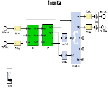
[image:2.612.78.258.459.612.2]B. Creating transmitter for SDR
Figure 3: SDR transmitter block
The transmitter block will convert the TDM (Time division multiplexed) data to FDM (Frequency division multiplexed) data. The TDM data provide an input port for subsystem or model. It produces the value of the subsystem input at the previous time step. TDM data is passed to the gateway in block which converts inputs in type simulink integer to a fixed point data type then the data is passed to a standard FIFO then the variable discrete signal is passed to the Xilinx Fast Fourier transform 7.1, it is implemented in radix 2 with a transform length 8 and clock frequency 250 MHz followed by 8 channels of polyphase FIR filter bank then the signals are down sampled and the FDM data is given to the receiver the transmitted block of SDR is as shown in Figure3 .
C. Creating receiver for SDR
Figure 4: SDR receiver block
D. Designed Channelizer for SDR
[image:3.612.69.267.66.245.2]The channelizers in SDR receivers must be realized to meet the stringent specifications of low power consumption and high speed [11, 12]. In SDR receivers, channelization is usually done using digital filter banks. We have designed a Polyphase filter[8] design that uses a combinational FIR filter bank and FFT block forming the channelizer for SDR as shown in Figure 5 this design is capable of operating at high data rates, owing to its combinational nature. We have designed 8 channels for the SDR [7].
Figure 5: channelizer of SDR
E. Creating channel sinks for SDR
[image:3.612.348.539.389.655.2]In the receiver the FDM data is again converted to TDM data it is down sampled by a factor of 8 [10]. The magnitudes of both the real and imaginary parts of the signals are extracted. The two signals parts are summed and sent to the channel output spectrum. The results are observed in the channel output spectrum scope there is considerable reduction of noise in the channels. Figure 6 shows the channel sinks.
Figure 6: output of channelizer
IV. FILTER DESIGN
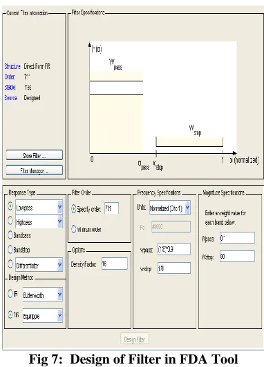
FDA Tool launches the Filter Design & Analysis Tool (FDA Tool). It is a Graphical User Interface (GUI) that allows us to design or import, and analyzes digital FIR and IIR filters [6]. We have designed a low pass filter that passes all frequencies less than or equal to 20% of the Nyquist frequency (half the sampling frequency) and attenuates frequencies greater than or equal to 50% of the Nyquist frequency. We have designed a FIR Equiripple filter with these specifications as shown in Figure7. MathWorks FDA tool can be used to create coefficients for the Xilinx FIR Compiler.
Fig 7: Design of Filter in FDA Tool
[image:3.612.59.278.409.529.2]4. Select Normalized (0 to 1) in the Units pull down menu in the Frequency Specifications area.
5. Enter (1/8)*0.9 for wpass and 1/8 for wstop in the Frequency Specifications area.
6. Enter 0.1 for Wpass and 90 for Wstop, in the Magnitude Specifications area are positive weights, used during optimization in the FIR Equiripple filter.
7. After setting the design specifications, click the Design Filter button at the bottom of the GUI to design the filter.
Add the FIR (FIR Compiler 5.0) filter block from the Xilinx Blockset DSP library to the design and associate the generated coefficients.
Add the FIR (FIR Compiler 5.0) filter block from the Xilinx Blockset DSP library to the design and constant block from Xilinx Blockset Basic Blocks
Double-click the FIR block and enter the required parameters in the filter specification and implementation tabs.
Add the FIR (FFT 7.1) filter block from the Xilinx Blockset DSP library to the design and constant block from Xilinx Blockset Basic Blocks
Double-click the FFT block and enter the required parameters in the filter specification and implementation tabs. The Radix-2 Lite, Burst I/O is selected, based on the Radix-2 architecture; this variant uses a time -multiplexed approach to the butterfly for an even smaller core, at the Cost of longer transform time. This architecture supports point sizes from 8 to 65536.
The Xilinx FIFO block implements a First-In-First-Out memory queue.
Values presented at the module's data-input port are written to the next available empty memory location when the write-enable input is one. By asserting the read-write-enable input port, data can be read out of the FIFO via the data output port (dout) in the order in which they were written. The FIFO can be implemented using block or distributed RAM. Full output port is asserted to one when no unused locations remain in the module's internal memory. The FIFO that is full is represented with user-specified precision. When the empty output port is asserted the FIFO is empty. Depths up to 64K are supported; Depth specifies the number of words that can be stored. The %full flag is set depending on a bit width specification [7].
V. SIMULATION OF SDR
Simulation may be defined as the process of verifying the functional characteristics of models at any level of abstraction. Simulation process can be started by clicking the Start Simulation button in the toolbar of the Model window. In our design Xilinx System Generator starts to process each block in
A. Compiling HDL netlist
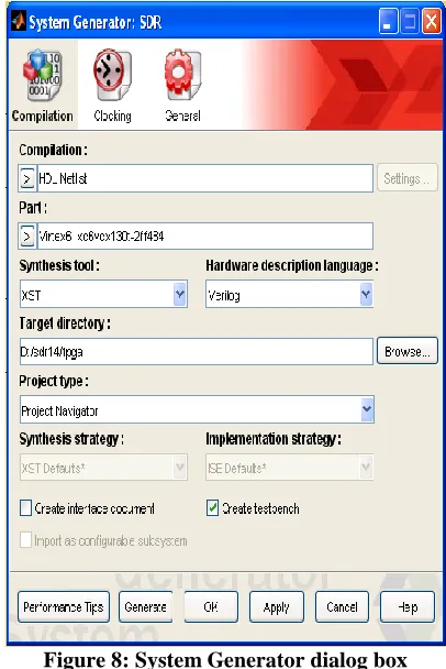
[image:4.612.342.545.287.591.2]The system generator dialog box for the compilation process is as shown in Figure 8. A system level design can be converted to the gate level representation using System Generator, which will automatically generate the verilog code for all Xilinx blocks contained in the hierarchy. Additionally, automatic generation of test bench enables design verification upon implementation. Figure 9 shows the compilation dialog box were we can observe the status of compilation and generation of HDL netlist.
Figure 8: System Generator dialog box
Figure 10: simulation dialog box
Performing the compilation and generation for HDL netlist may take few seconds and the simulation time allotted is 200000 simulink cycles, click yes the combined spectrum output and channel output spectrum scope waveforms will be displayed in MATLAB.
VI. IMPLEMENTATION AND SIMULATION RESULTS
A. Synthesis results of top module
The top module is the root of the design hierarchy for the purpose of implementation. In the top-level module, all the sub modules are combined to form the final system. The SDR code in verilog is exported from simulink/matlab and synthesized in Xilinx ISE Design suite 14.1.
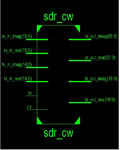
[image:5.612.80.254.57.170.2]The RTL schematic of SDR can be viewed as black box after synthesize of design is made. It shows the inputs and outputs of the system as shown in figure11. By double-clicking on the diagram we can view the Technology schematic of SDR as shown in figure12.
[image:5.612.72.264.418.657.2]Figure 11: RTL schematic of SDR
Figure 12: Technology schematic of SDR
The SDR code in verilog is exported form Xilinx system generator and simulated in Xilinx 14.1.The simulation waveforms are as shown. Thus in our work both inputs and outputs will be binary streams of data as shown in figure13.
Figure 13: SDR model waveform
B. Simulation Results
[image:5.612.331.556.431.608.2]Figure14: SDR combined channel spectrum output
Figure15: Channel output spectrum at the sinks
VII. CONCLUSIONS
A software defined radio is designed using Xilinx System Generator. The designed SDR can be used in real time application there is a promising decrease in noise by the design.
efficient communications systems that can be used in commercial arenas.
REFERENCES
[1] “The software radio architecture,” J.Mitola, Mitre corp.,Bedford,MA IEEE Communications Magazine, vol.33, no.5, pp. 26–38, May 1995.
[2] “Software radio architecture: a mathematical perspective,” J.Mitola,III Mitre corp.,McLean,VA IEEE Journal on Selected Areas in Communication, vol. 17, no. 4, pp.514-538, April 1999.
[3] [3]. PGA based power efficient channelizer for software defined radio, Meg Vootukuru,Systems Engineer,Syneren Technologies corporation.
[4] “SDRF Cognitive Radio Definitions”, Available at
http://www.sdrforum.org/pages/documentLibrary/documents/SDRF-06-R-0011-V1_0_0.pdf
[5] The Mathworks Inc, Simulink, Dynamic System Simulation for Matlab, Using Simulink,Natick, Massachusetts, U.S.A, 1999.
[6] “Filter Design and Analysis using FDATool of MATLAB”, Available at
http://www.mathworks.com/products/demos/shipping/signal/introfdatoolde mo.html?product=SG
[7] System Generator for DSP User Guide Release 10.1.1 April, 2008 [8] Channelization techniques for software defined radio, Lee Pucker Spectrum
Signal Processing Inc., Burnaby, B.C, Canada
[9] R.E. Chrochier et al., “Multirate Digital Signal Processing”, Prentice Hall, 1981.
[10] Interpolation and Decimation of Digital Signals-A Tutorial Review ronald e. crochiere, senior member, IEEE, and Lawrence r. rabiner, fellow, IEEE [11] Vinod, A. P., Premkumar, A. B., & Lai, E. M.-K. (2003). “An optimal
Entropy coding scheme for efficient implementation of pulse shaping FIR filters in digital receivers,” in Proc. of IEEE International Symposium on Circuits and Systems, vol. 4, pp. 229–232, Bangkok, Thailand.
[12] Vinod, A. P., & Lai, E. M-K. (2006). “Low Power and High-Speed implementation of FIR filters for software defined radio receivers,” IEEE Transactions on Wireless Communications, pp.1669–1675, no. 5, vol. 7.
AUTHORS
First Author – Rini Supriya .L, Dept of ECE, Reva ITM,
Bangalore 560 064, India
Second Author – Mr.Senthil Murugan, Deputy Manager, Dept
of Military RADAR, Bharat Electronics Limited, Bangalore 560 013,India
Third Author – Dr.R.C.Biradar, Dept of ECE, Reva ITM,