TERRESTRIAL-TO-SATELLITE INTERFERENCE IN THE
C-BAND: TRACTABLE CALCULATION TECHNIQUE
1LWAY FAISAL ABDULRAZAK, 2A. HAMEED
1Department of Computer Science, Cihan University, Sulaimanyia, Iraq
2Faculty of Manufacturing Engineering, Universiti Malaysia Pahang, Pekan, Malaysia
E-mail: [email protected] , [email protected]
ABSTRACT
This paper presents a research conducted on the interference mitigation between IMT-Advanced and Fixed Satellite Services (FSS). It covers a deterministic analysis for interference to noise ratio (I/N), adjacent channel interference ratio (ACIR) and path loss propagation, in order to determine the separation distances in the co-channel interference (CCI) and adjacent channel Interference (ACI) scenarios. An analytical model has been developed based on the deterministic analysis of the propagation model. The IMT-Advanced parameters have been represented by Worldwide Interoperability for Microwave Access (WiMAX) 802.16e. The impact of different FSS channel bandwidths, guard band separations, antenna heights and different deployment areas on co-existence feasibility are considered. The results obtained in terms of minimum required separation distance in three scenarios, co-channel, zero-guard band, and adjacent channel are analyzed.
Keywords: Interference, Separation Distance, Bandwidth, IMT-Advanced, Guard Band
1. INTRODUCTION
This paper addresses the (3400-4200) MHz band of the spectrum, which has been proposed by the
International Telecommunication Union of
Research (ITU-R) as the widest band that will be available, up to 100 MHz/channel, for the future International Mobile Telecommunication Advanced (IMT-Advanced) operational frequency. For FSS, C-Band is used in many countries, represented by thousands of strategic investments ranging from Tele-medicine and distant learning to disaster recovery [1]. Accordingly, any immediate transition in the use of this band to IMT-Advance services is considered unrealistic [2]. The super extended C-band 3400-4200 MHz is attractive for FSS because of its low absorption, highly reliable space to earth communication and wide service coverage. In addition, this frequency band is widely used by satellite operators in the countries with severe rain fade conditions due to almost zero rain-induced signal attenuation. C-band is also favorable to IMT-Advanced, because it allows multiple antenna technique implementations, and the use of smaller antenna for terminals and base stations; as well as enabling high space efficiency [1].
The co-channel interference (CCI) and adjacent channel interference (ACI) are issues that result of co-locating more than one service in one band.
However, CCI is the worst of the issues in the co-existence of both IMT-Advanced and FSS using the same frequency carrier. ACI results from other signals that are adjacent in the frequency to the desired signal.
The sharing results by using a Minimum Coupling Loss (MCL) and Monte-Carlo (MC) simulation link gave a required separation distance larger than 40km to avoid mutually harmful interference between two systems in co-channel and adjacent channel interference scenario [3, 4]. On the IMT-Advanced side, the Orthogonal Frequency Division Multiplexing (OFDM) is currently considered the most promising access schemes to support IMT-Advanced systems [5]. It is based on multi-carrier modulation technique that offers excellent performance in combating multi-path fading as well as superb efficiency in terms of using the available bandwidth [6]. In reviewing the literature, no data has been found on the association between clutter loss and frequency separation which represents the core of interference avoidance study. Therefore, this study is aimed at assessing the importance of radio propagation coverage and models.
both terrestrial and satellite propagation situations.
It is concluded that IMT-Advanced operating environments are dense urban, urban, suburban and rural, with several common characteristics, such as Interference-to-Noise ratio (I/N). The ITU-R452.14 propagation model is used in the terrestrial communications to account for the deteriorating effects of clutters on radio transmissions at frequencies above 0.7 GHz in different deployment environments. Subsequently, an easy to follow approach is needed in order to determine the
frequencies' co-ordinations with different
bandwidths.
2. INTERFERENCE ASSESSMENT
METHOD
The propagation model consists of interferer Adjacent Channel Leakage Ratio (ACLR) and receiver Adjacent Channel Selectivity (ACS). These two parameters will be incorporated into the wave propagation model in addition to the clutter loss effect. As a case study, one channel of MEASAT-3 C-Band downlink (36MHz bandwidth) and frequency coordination with WiMAX service (20MHz channel bandwidth) is considered for initial planning. The received power threshold is used as a benchmark for the interference between the two systems, while frequency offsets and geographical separations for different deployment environments are considered. The calculations are performed for 4 GHz frequency carrier, based on Interference to Noise ratio (I/N) of -10dB.
Intuitively by introducing clutters, smaller separation distance is achieved and vice versa. Path loss prediction in the case of Line Of Sight (LOS) is obtained by including the losses produced by the line-of-sight situation together with the losses produced by clutter models. This is summarized in Equation (1) [8]:
10 10
( )
92.44 20 log
20 log
10.25
1 tanh 6
0.625
0.33
k
GHz Km
d
a
L d
f
d
h
e
h
−=
+
+
+
−
−
−
(1)where d is the distance between the interferer and the victim receiver in kilometers, f is the carrier frequency in Gega Hertz and dk is the distance in km from nominal clutter point to the antenna (dk =0.02 km, 0.02 km, 0.025 km and 0.1 km for the
four deployment environments dense urban, urban, sub-urban and rural , respectively), h is the antenna height (m) above local ground level and ha is the nominal clutter height above local ground level (ha= 25 m, 20 m, 9 m and 5 m for the four deployment environments). The separation distance can be calculated as follows:
20 ( ) 92.5
20 ( ) ( ) Interferer
h vs
Log d I EIRP
Log F A G α
= − + −
− − +
(2)
Where EIRP is the effective isotropic radiated
power transmitted from the interferer, F is the
frequency in GHz and Gvs is related to the typical receiving FSS antenna gain [9]. Equation (2) accounts for the most important parameters affecting the radio propagation, which might also apparently be subdivided into other subparts.
For realistic consideration of interference, the ACLR and ACS are included and derived from Equation (2). The receiving gain of FSS station is called off axis antenna Gvs(α). The off axis angle value depends on the earth station location and the main receiving beam, where a typical receiving antenna gain can be calculated as Equation (3) [10]:
10 10
3 2
max
52 10 log ( ) 25 log ( )
2.5 10 ( )
10
0
( )
3.6
48
48
180
m o o vs o o D D G dBiG
α λ ϕλ
α
ϕ
α
α
α
− − − − × −
<
<
=
<
<
<
<
(3)Where Gmax is the maximum antenna gain
(38dBi), D=1.8m (satellite diameter) and λ is the
wave length in meter and is given by:
max 10
20
2 15 log (
)
m
D
G
D
λ
ϕ
λ
=
−
−
(4)In the simulation a value of -10 dB was considered to represent the local case study (the FSS elevation angle at the experiment location was 74o).
mentioning that receiver blocking and ACIR
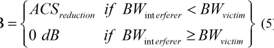
calculations are based on transmitter SEM and victim filter response powers [11]. The receiver blocking is considered in order to find the power degradation in decibel. This can be calculated as follows:
int int
B
0
reduction erferer victim
erferer victim
ACS
if BW
BW
dB
if BW
BW
<
=
≥
(5)Where, ACSreduction is the value of received signal
within the interference, for the case when the interferer bandwidth is less than the victim bandwidth. It is worth mentioning here that if both signals have the same bandwidth, ACS calculation will not be necessary and only the SEM of the interferer will rise to interference power in the case of CCI. Such a SEM is the 20 MHz channel bandwidth type-G WiMAX spectrum emission mask in [12]. WiMAX system featuring this type of SEM was envisaged as the next generation technology and is chosen for co-existence and sharing studies. Table 1 shows some typical values for mobile WiMAX’s SEM.
Table 1. Reference Frequency for SEM of Type-G (Wimax) [12]
Channel
separation (MHz) 0 0.5 0.5 0.71 1.06 2 2.5 WiMAX band
width from Fc (MHz)
0 10 10 14.2 21.2 40 50
Power loss (dB) 0 0 -8 -32 -38 -50
-50
The channel 20 MHz bandwidth is multiplied by a factor 0.5, which is the normalized frequency offset, in order to achieve a 10 MHz separation from the assigned frequency carrier. All the frequency offsets and the corresponding power spectral densities will conform to the following straight-line equation:
(
)
f
a
f
b
∆ =
∆
+
(6)Where ∆f denotes the frequency offset from the carrier, a represents the amount of attenuation in dB in the segment and b is the attenuation in dB at a certain frequency offset from the reference. Therefore, as the frequency offset becomes wider, the effect of ACLR will be less.
The FSS Channel selectivity is obtained by superimposing the front-end band-pass filter on an assumed typical IF (70 MHz) surface acoustic wave filter (36MHz bandwidth). So, ACS is the ratio of
[image:3.595.94.293.213.248.2]receiver filter attenuation over its pass-band to by the receiver’s filter attenuation over an adjacent frequency channel. As an example for practical measurements of the ACS values, Table 2 represents the channel bandwidth and the amount of power reductions as the signal deviated from the frequency carrier [13].
Table 2: FSS Receiver Channel Selectivity Attenuation Front-End Plus IF
Channel separation (MHz)
0 0.5 0.58 0.66 1.38 1.6 6 2.5
FSS bandwidth from fc (MHz)
0 18 21.1 24 50 60 90
Power loss
(dB) 0 0 -40 -48 -61 -66 -75
Table 2 shows that the power reduction corresponds to the amount of separation distance from the frequency carrier, which correspondingly increases the selectivity of adjacent channel. The ACS reduction at the CCI scenario and the victim bandwidth can be relatively calculated in different ways. Using the power attenuation in Tables 1 and 2, the ACS reduction reaches up to 34.5 dB for the FSS (36 MHz) and WiMAX (20 MHz) channel bandwidths. This value can be used when the frequency offset is 0 MHz. In order to calculate the adjacent channel interference, the ACIR should be considered by reducing the interference powers of the interferer ACLR and the victim ACS which are located on different central frequencies [14]. The ACIR is given by:
(
/10) (
1 /10)
1 110 log 10 10
10
ACLRIMT ACSFSS
ACIR
−
− −
=
+
(7)
Where ACLR is the ratio of the power over signals pass-band to the interference power over receiver pass-band and ACS is the ratio of the receiver pass-band attenuation to the receiver filter adjacent channel attenuation. Therefore, the interference power can be calculated as a summation of out-of-band interference and in-band interference. In order to calculate the separation distance required to achieve the co-existence between two systems in ACI scenario.
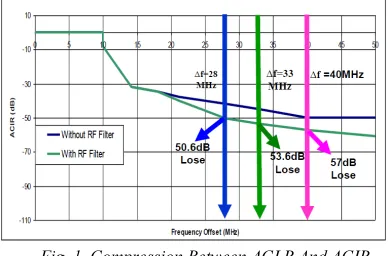
interference in the adjacent channel, the ACIR
[image:4.595.308.509.74.209.2] [image:4.595.91.285.210.338.2]should be considered by reducing the interference powers of the interferer and the victim that are located in different central frequencies [14]. As a result the ACIR has been calculated and obtained in Figure 1 for ∆f= 28, 33 and 40 MHz based on ACS and ACLR.
Fig. 1. Compression Between ACLR And ACIR.
Figure 1 shows that frequency offsets have been chosen to get guard bands of 0, 5MHz and 12 MHz, respectively. Clearly, the ACS of FSS receiver plays an important role in reducing the harmful adjacent channel leakage of the receiver by 8.6, 8.6 and 7 dB, respectively, when ∆f=28, 33 and 40 MHz. Using ACIR offers other good features on the analytical model. These features include the same method for studying the interference in the larger guard band and the ability to obtain the co-existence for a required separation distance by controlling the frequency offset between two systems.
3. ASSESSMENT SCENARIO
Three scenarios are considered in this paper. The first scenario shows the interfering signal falling within the operating band of the victim FSS receiver (they are co-channeled). In the second scenario, both victim and interferer bands fall outside each other and are located contiguously (adjacent). Nevertheless, inserting a guard band in between the two systems forms the third co-existence scenario, where interference is therefore minimal. In each of the interference scenarios, there is the need to consider a certain procedure in order to achieve the co-existence.
For the purpose of analyzing the co-existence in various environments, these three scenarios will be used and simulated based on the aforementioned
deployment areas. By considering the
channelization plan for MEASAT downlink transponders, one channel is proposed at 4 GHz central frequency as illustrated in Figure 2.
Fig. 2. MEASAT-3 Spectrum Plan With The Proposed Channel.
Figure 2 depicts the downlink channelization plan for MEASAT-3 geostationary satellite orbit where the proposed 20 MHz WiMAX replaces the 36 MHz FSS channel. Consequently, a maximum of 12 MHz guard band may be obtained when such a proposal is applied. This outcome was actually the driving impetus behind the specified frequency offset.
A fixed protection ratio has been used as a criterion for the interference scenarios in order to limit the interference, by using I/N = -10 dB.
MEASAT satellite has 24 transponders and each of the transponders has a maximum of 36 MHz channel Bandwidth. In order to determine the maximum possible level of in-band interference at the FSS receiver, the following expressions have been used:
(10 5.7)
C
I
C
dB
I
=
N
+
N
=
+
(8)10
10 log (
)
C
C
KTB dBw
N
=
+
(9)(
15.7)
143
inband
I
=
C
−
dBw
= −
dBw
(10)where C is the carrier power at the receiver in dB, C/N is the required carrier to noise ratio which is specified as a 5.7dB minimum [15], Iin-band is the required protection ratio, K is Boltzmann constant = 1.38× 10⁻²³ J/k, T is the temperature in Kelvin and B is the noise bandwidth in Hz [2]. With the carrier frequency at 4 GHz, the overall propagation model may be rewritten as follows:
10
20 log ( ) ( ) 104.58
_
(10.25 k 1 tanh 6 0.625 0.33)
WiMAX vs
d
a
d I EIRP G
ACIR corr band
h e
h
α
−
= − + + −
+ +
− − − −
(11)
[image:4.595.307.521.629.701.2]BWWiMAX < BWFSS. Otherwise, Corr_band =
-10log (BWWiMAX/BWFSS), when BWWiMAX > BWFSS. Therefore, when the bandwidth of FSS is 230 kHz, the correction band is given by the following expression:
6
10 3
20 10
C _ 10 log ( ) 19.4
230 10
WiMAX
FSS
orr band = − l × = − dB
×
(12)
The value of correction band is used in the simulation processes.
4. SIMULATION PARAMETERS
A simulation of two base stations, WiMAX 802.16e and FSS, has been conducted by proposing the most appropriate parameters for WiMAX 802.16e and the used parameters for the FSS receiver. These parameters are quite compatible with those proposed in the WRC-07 [16].
For WiMAX base station, it is proposed to be macro station coverage with a SEM type-G (model number: UTIS EN301021), with the antenna height fixed to 30 m above ground level. Antenna gain proposed to be 18dBi for 3 sectors base station and power transmitted of 43 dBm is applied for the WiMAX systems. The frequency carrier is attuned in order to benefit the co-existence in the adjacent channel interference. A really rare case is considered when co-channel interference happens at the 4000MHz frequency carrier.
For FSS an antenna of variable heights (1.8 m and 5m) is used to highlight the fact that the position of the FSS receiver on the ground can reduce the separation. The FSS antenna gain is 38 dBi, frequency carrier is 4000 MHz, elevation angle is 74o, Azimuth 263.7o, dish diameter is 1.8m, bandwidth of 0.23MHz and 36MHz, and two
interference levels were considered
-143dBw/36MHz and -165dBw/0.23MHz. Referring to the effect of clutter loss, it is noticed that increasing the FSS receiver height corresponds to extending the separation distance. Therefore if the FSS base station is higher than the clutter height, then the minimum distance required will remain fixed. The FSS parameters reflect the fact that a fixed position of FSS receiver is used, while the WiMAX ones apparently show movable type of WiMAX base station parameters.
5. MINIMUM SEPARATION DISTANCE BETWEEN WIMAX AND FSS AT 36 MHZ
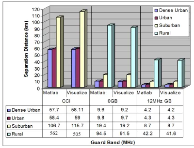
The results of separation distance have been summarized in Figure 3, when the values of
[image:5.595.315.515.200.353.2]frequency offset between carriers are 0, 28 and 40 MHz. By fixing the limit of I/N to -10dB as a protection ratio, the calculations for co-channel and adjacent channel are performed for the current frequency band 4GHz (these include interferers’ ACLR and receivers’ ACS).
Fig. 3. Results Of Separation Distance For Four Different Environments At Different Frequency Offsets.
Figure 3 shows the separation distance between FSS ES and WiMAX in four different deployment areas, when a FSS antenna height of 5 m is used for CCI and ACI. It shows that nature of clutter could affect the overall results. It can be used for different deployment environments which justified the effects of using different antennas, clutter heights and
nominal building separations. A minimum
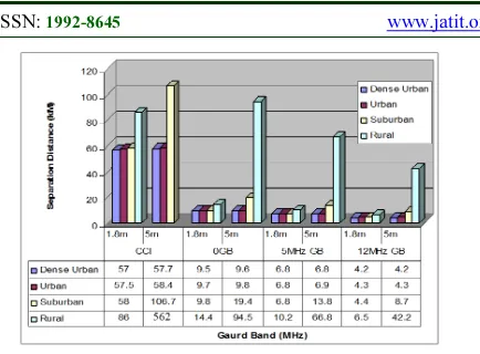
Fig. 4. Separation Distance Using Variable FSS Antenna Heights For Four Different Environments At
Different Frequency Offsets.
However, the clutter loss is directly related to the antenna heights. Therefore, for an antenna height of 1.8 m, clutter height losses are 19.74 dB, 19.73 dB, 19.5 dB and 15.4 dB as isolation provided in the dense urban, urban, suburban and rural areas, respectively. On the other hand, when the FSS height is 5 m, then the corresponding clutter isolation will be 19.65 dB, 19.55 dB, 13.6 dB and -0.32 dB, respectively.
By referring to the propagation model, the clutter loss in the rural area coverage must be set to a value less than zero. These values will definitely increase the separation distances, and consequently it is most difficult to achieve the co-existence in the rural area, compared to other deployment areas.
6. MINIMUM SEPARATION DISTANCE BETWEEN WIMAX AND FSS AT 0.23 MHZ
When FSS bandwidth of 0.23 MHz is used to conduct the assessment, the interference level was -165 dBW/0.23 MHz. It can produce a longer separation distance due to the increase in the receiver sensitivity. When the victim bandwidth is less than the interferer bandwidth, the sufficient separation distance for a specific guard band can be tuned manually. Even though without incorporating a mitigation technique in this scenario, the guard band required to protect the victim is efficient.
The Interference from WiMAX (20 MHz bandwidth) to FSS (0.23 MHz bandwidth) was simulated and interference to noise protection ratio of -10 dB was considered. Thus, the scenarios of CCI and ACI are considered to represent the frequency dimension as a possible mitigation technique. This is used to reduce the separation distance between the two services as presented in Figure 5.
Fig. 5. The Separation Distance Between Wimax And FSS When FSS Bandwidth Is 0.23 Mhz In The Four Deployment Areas For Different Frequency Offsets.
Figure 5 shows that minimum required separation distance of 49.1 km could be achieved with 1.8 m FSS receiver height in the ACI scenario under dense urban area environment. However, the worst case of interference is experienced when a rural area was used as the deployment scenario in the CCI. The minimum separation distances required for the urban area deployment were 4.3 km and 49.6 km for 36 MHz and 0.23 MHz FSS channel bandwidths, respectively. Note that a 12 MHz guard band and 1.8 m antenna height were used. Analyses of Figure 11 have revealed that three types of frequency offsets (0, 10.15 and 22.5 MHz) are used to compare the minimum separation distances in the four environments.
By comparing Figure 4 with the results presented in Figure 5, it is observed that when FSS receiver bandwidth is 36 MHz, the possibilities of co-existence are increased due to separation distance reduction. However, the noise level of a victim FSS is improved to -143 dBW/36 MHz and the adjacent channel scenario gave a wide separation between carriers. This indicates that the higher the difference between victim receiver bandwidth and that of the interferer, the less the effects of interference from the transmitter. Alternatively, it is observed that when the frequency offset is more than half of the interferer bandwidth, the separation distance becomes significantly small.
7. CONCLUSIONS
A more straightforward approach to the protection ratio for future WiMAX 802.16e is derived and illustrated in order to achieve the frequency coordination with the FSS receiver. In the co-channel interference case, it is found that the
adjacent channel selectivity reduction is
[image:6.595.91.308.105.265.2]interferer’s bandwidth is larger than that of the
victim, another factor must therefore be added to account for mask discrimination correction. The results have indicated that the required distance, as well as frequency separation, decreases as victim receiver bandwidth increases and vice versa.
It is found that the receiver’s adjacent channel selectivity reduction is unnecessary in the CCI scenario when both of services have the same bandwidth. However, if the interferer’s bandwidth is larger than that of the victim’s, then another factor should be added to account for mask discrimination correction.
It is observed that the separation distance decreases with an increasing channel bandwidth. However, higher bandwidth implies higher noise in the receiver, and consequently a higher noise floor level. As a result, the interfering signal strength (dBm) becomes stronger as the distance is nearer. Therefore the interference becomes more visible when the interferer bandwidth is greater than that of victim. On the other hand, less interference is encountered when the victim receiver bandwidth is wider than that of interfering transmitter. This is due to the adjacent channel leakage ratio, which accounts for the fact that wider bandwidth of interferer results in lower spectral emissions, especially in the adjacent bands. Moreover, the proposed approach presents a tractable and systematic work flow for the calculation of protection ratio. The proposed technique is also applicable to a wide range of frequencies and bandwidths by simply calculating the required threshold degradation, ACLR and ACS.
ACKNOWLEDGEMENT
Dr. Lway Faisal Abdulrazak would like to thank the department of Computer Science at Cihan University, Sulaimanyia, Iraq, for their financial support in this research work. Similarly, Dr. A. Hameed would like to extend his gratitude and appreciation to Universiti Malaysia Pahang (UMP) Vot. RDU 130387 for funding this research.
REFRENCES:
[1] ITU-R Document 8F/1015-E. Sharing studies between FSS and IMT-Advanced systems in the 3400-4200 and 4500-4800 MHz bands. 2006. [2] ITU-R WP 8F/TEMP 432 rev.2. Working
document towards a PND report on sharing studies between IMT-ADVANCED and the Fixed Satellite Service in the 3 400- 4 200 and 4
500-4 800 MHz bands. ITU-R Working Party 8F. August 2006.
[3] Han-Shin Jo, Hyun-Goo Yoon, JaeWoo Lim and Jong-Gwan Yook. An Advanced MCL Method for Assessing Interference Potential of OFDM-Based Systems beyond 3G with Dynamic Power Allocation. Proceedings of the
9th European Conference on Wireless
Technology. UK. September 2006. pp. 39-42. [4] Seidenberg, P. Althoff, M.P. Schulz, E.
Herbster, G. Kottkamp, M. Statistical of Minimum Coupling Loss in UMTS/IMT-2000 Reference Scenarios. Vehicular Technology Conference VTC‘99, IEEE VTS 50th. Vol:2, Publication Year: 1999, pp: 963 - 967.
[5] ITU-R WP8F Contribution. Proposed MIMO Channel Model Parameters for Evaluation of Air Interface Proposals for IMT-Advanced. Document 8F/1149-E, Question ITU-R 229/8, ITU-R WP8F Meeting in Cameroon, January 2007.
[6] X. Li and L. J. Cimini Jr. Effects of clipping and filtering on the performance of OFDM. IEEE Commun. Letters. May 1998. vol. 2, pp. 131-133.
[7] Recommendation ITU-R P.452-12. Prediction Procedure for the Evaluation of Microwave Interference between Stations on the Surface of the Earth at Frequencies above about 0.7 GHz. Geneva, Switzerland. May, 2007.
[8] Lway Faisal Abdulrazak, Zaid A. Shamsan and Tharek Abd. Rahman. Potential Penalty Distance between FSS Receiver and FWA for Malaysia. International Journal Publication in
WSEAS Transactions on
COMMUNICATIONS. ISSN: 1109-2742, Issue 6, Volume 7, June 2008, pp. 637-646. [9] 3G Americas SM report. 3GPP Technology
Approaches for Maximizing Fragmented
Spectrum Allocations. July 2009.
[10] Document AWF-3/17 .Assessment of potential interference between Broadband Wireless Access (BWA) in 3.4-3.6 GHz band and Fixed Satellite Service (FSS) in 3.4-4.2 GHz band. Office of the Telecommunications Authority (OFTA) Hong Kong. September 2006. [11] Hamid R. K., Martin F., Gérard L., and Eric F.,
European harmonized technical conditions and band plans for broadband wireless access in the 790-862 MHz Digital Dividend spectrum.
Conference of European Post &
Telecommunications Administrations.
[12] CEPT ECC Rep. 100. Compatibility studies in
the band 3400-3800 MHz between broadband wireless access (BWA) systems and other services. Bern, Switzerland. Feb, 2007.
[13] Z. A. Shamsan, A. M. Al-hetar, and T. Abd. Rahman. Spectrum Sharing Studies of IMT-Advanced And FWA Services Under Different Clutter Loss And Channel Bandwidths Effects. Progress In Electromagnetics Research, PIER 87, 2008. pp. 331344.
[14] CEPT Rep. 19. Report from CEPT to the European Commission in response to the Mandate to develop least restrictive technical conditions for frequency bands addressed in the context of WAPECS. October.2008.
[15] Document AWF-3/17 .Assessment of potential interference between Broadband Wireless Access (BWA) in 3.4-3.6 GHz band and Fixed Satellite Service (FSS) in 3.4-4.2 GHz band. Office of the Telecommunications Authority (OFTA) Hong Kong. September 2006.
[16] IST-2003-507581 WINNER. WINNER