© 2015, IRJET.NET- All Rights Reserved
Page 735
TIME SYNCHRONIZATION OVER AN AIRCRAFT NETWORK USING
PRECISION TIME PROTOCOL
P. Jayaraj
1, Shailee. S
21
PG student, Department of Electronics & Communication, CMRIT Bangalore, Karnataka, India
2Assistant Professor, Department of Electronics & Communication, CMRIT Bangalore, Karnataka, India
---***---Abstract -
Time synchronization is important conceptin computer networking. It helps the computers connected in a network operate in synchronization . In an aircraft , lots of computer system are interconnected in a network. These systems are connected to a central main system. Central main system controls all the subsystems. All the systems operate in clock time related to Central main system. But there is a difference in clock time in sytems when compared to Central main system and other subsystems. This is mainly due to delay in transmitting the clock time from central main system, clock jitter, timer variation in subsystems and different types of clocks used by each systems. Because of this , there will time difference between systems. In order to reduce this time difference between the sytems connected in network, this project has been taken up. This paper presents about the implementation of Time synchronization using IEEE std 1588 (Precision Time Protocol). Aim of this project is to implement this IEEE std 1588 (Precision Time Protocol) a time synchronization protocol on ARM cortex m3 processor and reduce the time difference between the systems to under 10 microseconds. Here , two end systems are taken up ( Stellaris LM3S9B96 board) to test this protocol. This protocol operates in master slave hierarchy. One of the end system is programmed as master and other is programmed as slave. Slave synchronizes its time with that of master. Programming language used for implementing this protocol is Embedded C. The software tool used for coding is Keil uvision 4. Ethernet cable is used as a connection medium between the end systems.
Key Words:
PTP, Timestamp, Ethernet
1. Introduction
Computers are a part of our daily life. Computers are interconnected with one another using networks. They share data using networks. Time synchronization is important concept in computer networking. As computers are interconnected in a network, they do not usually operate in synchronization. Each system connected in a network might operate at different clock time. It will be impossible to correlate data without time synchronization. Clocks in computers operate in different time mainly due to different types of clocks used by system in a network, clock jitter, delay in transmitting clock time from the main systems in a network ( Eg- Servers).
Time synchronization is done in computer networks for mainly following reasons- network usage, tracking security breaches, or problems affecting a large number of components can be nearly impossible if timestamps in logs are inaccurate. Time is often the critical factor that allows an event on one network node to be mapped to a corresponding event on another, To reduce confusion in shared filesystems, it is important for the modification times to be consistent, regardless of what machine the filesystems are on, in automation industries where all systems should operate at proper time, Billing services and similar applications must know time accurately.
© 2015, IRJET.NET- All Rights Reserved
Page 736
2. LITERATURE SURVEY
Computers on a network interacts with one another using Networking models . Usually computer network works on OSI or TCP/IP model. OSI consists of seven layers and TCP/IP consists of five layers. They follow protocols and standards when data is sent and received from one to another layer. Multilayers are used for security and protection[1].
Systems are connected in a network by connecting medium like RS232, RS 485, Ethernet, Wifi etc. RS 232 is a full duplex, wired, asynchronous serial communication interface. RS232 extends the UART communication signals for external data communication. RS 232 is a point to point communication interface and devices involved in RS 232 communication are called Data Terminal Equipment(DTE) and Data Communication Equipment(DCE). RS232 supports only point to point communication and not suitable for multi drop communication. It uses single ended data transfer technique for signal transmission and thereby more susceptible to noise and it greatly reduces the operating distance.
RS422 is a serial interface standard from EIA for differential data communication. It supports data rates up to 100 kbps and distance up to 400 ft. RS422 supports multi drop communication with one transmitter device and receiver devices up to 10.
RS 485 is enhanced version of RS422 and it supports multi drop communication with up to 32 transmitting device and 32 receiving devices in the bus uses the addressing mechanism to identify slave devices.
Ethernet is latest connecting medium in networks. They have a very high speed compared to RS485. Nowadays, they are being used in aircraft networks. Ethernet is mostly used in LAN networks.
In aircraft, systems are connected through buses. One of the dominant bus architecture used in Aircrafts is MIL std 1553. It has bus controller, remote terminal, bus monitor. It communicates at a speed of around of 1Mbps. It can address upto 32 remote terminals[8]. But this bus implementation is very costly. It is very heavy and it uses a lot of power.
As the number of systems connected in an aircraft are increasing, there is a need for more bandwidth. MIL std 1553 has pretty low bandwidth. There is a need for new interconnection system needed to overcome the limitations of MIL std 1553b data bus. One of the high speed networks called Full duplex switched Ethernet (AFDX) is an attractive candidate to replace MIL std 1553b. AFDX is based on Ethernet Technology[9].
Ethernet has got high speed , around 3 Mbits – 10Gbits per second. It uses low power compared to MIL std 1553b. Ethernet. It has got standardized software infrastructure. MIL std 1553 never had a standard software API[7].
Time synchronization is process of making systems connected to network operate in synchronization. NTP(Network Time Protocol) is the main protocol used in networks for time synchronization. NTP has been there from many years. NTP provides time synchronization upto milliseconds. Precision Time Protocol(PTP) is new time synchronization protocol . It is defined in IEEE std 1588. This protocol was introduced in early 2000s[2]. PTP can synchronize time in microsecond to nanosecond level. PTP is mainly used in LAN networks.
To implement Precision time protocol(PTP), there are different types of clocks that are used. Two main clocks are ordinary clocks and transparent clocks[3]. PTP uses messages to communicate and do time synchronization. Ordinary clocks provide good time synchronization but they can be used only between end systems implementing PTP. They cannot be used in a system that does not implement PTP( eg: switches, routers). Transparent clocks can be used inbetween non-PTP systems, but their synchronization is less compared to ordinary clocks.
PTP has got two versions - PTP version 1 and version 2. For systems implementing PTP master slave topology is followed for synchronizing. PTP version 2 has transparent clocks. PTP version 1 does not have this. PTP version 2 has a better synchronization accuracy than version 1. PTP version 2 has shorter message length. For synchronization two mechanism is followed – Delay request response mechanism and Peer delay mechanism.
For implementing PTP, systems communicate with each other using messages to synchronize time. There are two different types of messages- event messages and general messages[3]. Event messages are time critical and are used in synchronization. General messages are used to notify the errors. The event message used in Ordinary clocks are Sync, delay_req, follow_up, delay_resp.
© 2015, IRJET.NET- All Rights Reserved
Page 737
3. METHODOLOGY
Here , Precision time protocol is implemented in a Stellaris LM3S9B96 board. Programming language used is Embedded C. Software tool used is keil 4 version. PTP version 2 is used. It follows master slave topology. Two Stellaris LM3S9B96 are taken as end systems. One is programmed as master and other as slave. Here timestamps are taken at the data link layer, which is to be used for time synchronization. Two LM3S9B96 are connected by Ethernet cable. The test equipment used is mixed signal oscilloscope to test upto how much level the pulses are synchronized.
Fig -1: Block implementation of project
The data flow of the project is shown-
Master Slave
[image:3.595.309.535.186.399.2]
Fig -2 : Data flow of model of project
Figure 1 shows the block level implementation of the project and figure 2 shows the data flow model of project. In Stellaris LM3S9B96, microDMA controller and Ethernet controller is used for data transfer. Here, timestamps are taken in the data link layer for time synchronization. Here, messages are sent from software level. Messages then pass through microDMA, which is then given to Ethernet controller. It is then given to Ethernet for transmission.
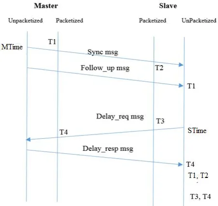
[image:3.595.37.284.273.388.2]In PTP , master and slave use messages to communicate and synchronize with each other. The messages are Sync, Follow_up, Delay_req and Delay_resp . These messages are used for Ordinary clocks. The synchronization technique called Delay request response mechanism is shown in figure 3.
Fig -3 : Synchronization Technique
The steps for synchronization are given –
1. First Master sends Sync message. It takes the master timestamp before sending (MTime) and puts time into Sync message .While sending it notes down time T1 after putting into Ethernet controller, where it gets packetized. The message is then sent to slave.
2. When message reaches the slave Ethernet controller, the time of receiving the message is noted down (T2).
3. Right after Master sends the Sync message, it sends the Follow_up message .In Follow_up message, timestamp T1 is put and sent to the slave.
4. Now slave receives the Follow_up message. It takes the timestamp T1.
5. Now slave sends a delay_req message to the master. While sending Slave timestamp(STime) is noted. After putting the message into Ethernet controller, timestamp T3 is noted.
6. Master receives the delay_req message.The time of receiving in Ethernet controller is noted down(T4). It then sends the delay_resp message.
LM3S9B96
LM3S9B96
CRO
Ethernet
Software
microDMA
Physical
Hardware Physical microDMA Software
[image:3.595.59.237.448.625.2]© 2015, IRJET.NET- All Rights Reserved
Page 738
Before sending to Ethernet controller, time T4 isput into message and sent.
7. Slave receives the delay_resp message with timestamp T4. Now slave has timestamp T1, T2, T3, T4.
8. Now slave applies PTP synchronization technique to calculate the delay and shift its time to that of master-
Delay= ((T4 –T1) – (T3 – T2)) / 2 Master packeting time = T1- MTime Slave packeting time = T3 – STime
Shift time = (T2 – T1) + Delay + Master packeting time + Slave packeting time.
4. RESULTS
The master and slave communicate with each other and slave synchronizes its timing pulse upto to microsecond interval . The output of the master and slave is checked in CRO.
Snapshots of the CRO based output is shown:
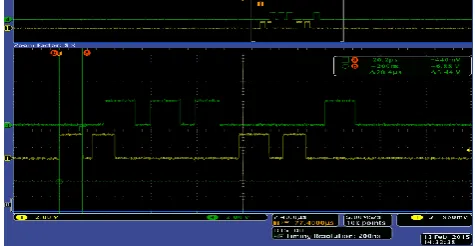
Fig -4 : The top waveform is slave and bottom is master. Here, time synchronization is not applied. The thick pulses are the timing pulses and thin pulses are PTP pulses. The time difference between slave and master timing pulse is around 253 ms
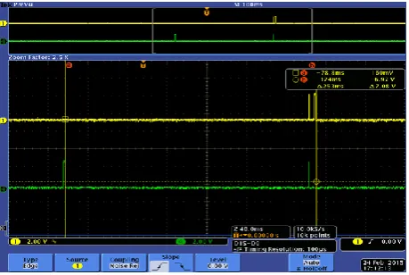
Fig -5 : The bottom waveform is master and top is slave. Here Time synchronization is applied(PTP). The timing pulses are synchronized. The thin pulses are PTP pulses.
Fig -6 : The following figure shows magnified output of time synchronized waveform. The width of timing pulses are around 2ms.
[image:4.595.319.548.98.231.2] [image:4.595.319.547.283.409.2] [image:4.595.47.277.406.560.2] [image:4.595.318.549.462.611.2]© 2015, IRJET.NET- All Rights Reserved
Page 739
Fig -8 : The snapshot shows enlarged view of PTP pulseswhich are used for synchronization. The bottom waveform is master and top is slave. The first pulse in master is Sync, then follow_up, then delay_req, then delay_ack. The pulses in slave are Sync, follow_up, delay_req, delay_resp.
5. CONCLUSION
The Precision Time protocol was implemented and tested in 2 end systems (LM3S9B96). Successfully, time difference was reduced to below 10 microseconds. Without PTP , time difference between master and slave was 253 ms. After using PTP, time difference between master and slave was brought down to 1.08 microseconds.
ACKNOWLEDGEMENT
I express my sincere thanks to Mr. Prabhulla Chandran, Scientist G, Aeronautical Development Agency(ADA) for giving me opportunity and support to work on this project in ADA. I express my sincere thanks to Mr. Ashwani kumar , Scientist C, Aeronautical Development Agency (ADA) for giving me full guidance and suggestions throughout the project work.
REFERENCES
[1] Data communications and networking, Behrouz A. Forouzan.
[2] Precise Time and Frequency Inc.
[3] IEEE standard for Precision clock synchronization protocol for Networked Measurement and Control system.
[4] blog.meinbergglobal.com. [5] www.arm.com.
[6] Stellaris LM3S9B96 microcontroller data sheet. [7] cotsjournalonline.com
[8] www.linkedin.com/pulse/mil-std-1553-v-arinc-429-kobbe-farwick.
[9] Full Duplex Switched Ethernet for Next Generation ”1553B”-based Applications by A Mifdaou.
BIOGRAPHIES
Mr. P. Jayaraj is currently doing M.tech in VLSI and Embedded systems in Department of Electronics and Communication in CMR Institute of Technology Bangalore. Has done B.E in Electronics and Communication
[image:5.595.42.280.102.225.2]