Abstract—The circulating fluidized bed (CFB) boiler combustion system is a complex multivariable dynamic system, holding characteristics, such as nonlinearity, strong coupling and parameters time-varying. These characteristics bring many difficulties in designing controller for such complex system. In this paper, a direct type of multivariable fuzzy controller is designed on the basis of the established relationships between output (u) and deviation (e), deviation change rate (ec), time constant (Tc), lag time (τ). Some simulations are conducted to illustrate the performance of the designed controller. The simulation results suggest that the designed multivariable fuzzy controller can not only eliminate the coupling between loops effectively, but also reduce the regulating time. Using the designed controller can therefore improve the dynamic performance of the CFB system.
Index Terms—multivariable control, fuzzy control, circulating fluidized bed (CFB), boiler combustion system
I. INTRODUCTION
irculating fluidized bed (CFB) boiler is a typical complex multivariable dynamic system, which holds many merits such as high fuel flexibility, and combustion efficiency, and low pollution emissions. It has been widely used in the thermal power, metallurgy and other industries. However, to make the CFB boiler work automatically under a preset efficient condition is difficult but important in practice. Hence, a strategy used to design robust controller is necessary for optimized operation.
Recently, some conventional control methods [1-4] are available. Nevertheless, these conventional control methods are difficult to achieve good performance due to some reasons including the complicated structure of the combustion system, the complexity of combustion mechanisms and the characteristics of the combustion system such as nonlinearity, time-varying, large delay, and strong coupling,
Fuzzy control methods can be effectively used to solve a wide range of control problems of which the objects hold nonlinearity and time-varying [5-7]. Therefore, there are some literatures making some contributions in designing fuzzy controller for CFB boiler combustion system.
Fu et al. [8] designed a fuzzy PID controller for the bed temperature of a circulating fluidized bed boiler. However, the controller structure was too complex, and it was designed
All of the authors are from School of energy and environment, Southeast University, Xuanwu District, Nanjing 210096, China(Corresponding Email: [email protected]).
without considering coupling between the loops. Wang et al. [9] proposed a control system composed of a PID controller and a fuzzy controller. However, the control system has poor adaptability. Cheng et al. [10] made a dynamic feedforward decoupling of CFB boiler combustion system, and designed a self-adapting fuzzy PID controller. While, the fuzzy control rules were empirically obtained, they did not put forward the principle of fuzzy control rules. Hence a multivariable fuzzy controller was designed in this present work.
Based on the analysis of the CFB boiler combustion control system, the present paper put forward the principles of the fuzzy control rules. With those rules, a direct type of multivariable adaptive fuzzy controller was designed. The controller can eliminate the coupling between loops, and has good adaptability.
II.THE CONTROL TARGET ANALYSIS
Usually, the control targets for the CFB boiler system include main steam pressure, oxygen level in flue gas, bed temperature, bed pressure, and pollutant emissions. In the present paper, the main steam pressure, bed pressure, and bed temperature were put as the controlled objects.
A. Main steam pressure control
Main steam pressure is an important index of superheated steam quality. CFB boiler often participates in power grid load adjustment. Once the load changes, the production and consumption rates of the steam are transiently inconsistent. It leads to the variation of the main steam pressure, therefore affect the quality of the steam. At this time, the input of fuel should be adjusted to change the output of boiler, and to maintain the stability of the main steam pressure [11].
B. Bed pressure control
Bed pressure is an indicator of the thickness of fluidized bed material. On one hand, if the bed pressure is too high, the quality of bed material fluidization will decline. Many large particles turn to accumulate at the bottom of the bed. It will endanger the operation of the boiler. On the other hand, if the bed pressure is too low, it is difficult for the bed material to form a dense phase zone. So the bed pressure must be maintained within a certain range [12].
C. The bed temperature control
Usually, the bed temperature of CFB boiler is kept between 850 and 950 ℃, and not allowed to be higher than 970 ℃, or lower than 800 ℃. A higher bed temperature will cause bed agglomeration and furnace slagging, and it will also increase NOx formation. A lower bed temperature will cause flameout [13]. Therefore, the bed temperature should
Multivariable Fuzzy Control of CFB Boiler
Combustion System
Yu-Fei Zhang, Li-Wei Xu, Pei Chen, Xiao-Chen Guan, Geng-Jie Wang
be maintained in a certain range as well. However, the bed temperature will rise when the CFB boiler load increases. Hence, if the boiler-load grown up, the bed temperature can be allowed to fluctuate within a certain range while taking control measure is unnecessary [14].
The main influence factors of the CFB boiler combustion system include the opening of return material valve (μν: %), the speed of slag cooler (Q: rpm), and the quantities of coal (B: t/h) and primary air (F1: km3/h). They are schematically shown in Figure 1.
III. MULTIVARIABLE FUZZY CONTROLLER
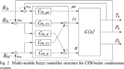
A. The structure of multivariable fuzzy control system
We can design the fuzzy controller without considering the coupling between bed temperature loop and main steam pressure and bed pressure loops. The multivariable fuzzy controller architecture of CFB boiler combustion system is shown in Figure 2.
B. The principles of multivariable fuzzy control rules
The establishment of the fuzzy control rules is the key of the fuzzy controller design. According to the characteristics of the control system and the features of the objects, we formulated five design principles of fuzzy control rules described as follows.
Design principle 1: Fuzzy classification and automatic adjustment (variable universe)
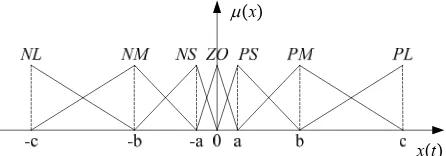
The fuzzy variables are divided into seven grades: NL means "large negative", NM means "middle negative", NS means "small negative", ZO means "zero", PS means "small positive", PM means "middle positive ", and PL means "large positive ". Fuzzy language [PL,PM,PS,ZO,NS,NM
,NL] are represented by [-3,-2,-1,0,1,2,3]. In order to adapt to the changes of the object properties, the strategy of variable universe fuzzy variables are used. The
controller can automatically change the universe of fuzzy variables size.
Design principle 2: Synchronous design of fuzzy controller and feedforward compensation fuzzy controller
The functions of the fuzzy controller and the feedforward compensation fuzzy controller are different. The fuzzy controller is used to eliminate the main circuit deviation, while the feedforward compensation fuzzy controller is used to eliminate the coupling between loops. Take the RPb-Pb
loop for an example, the role of CPb-F1 fuzzy controller is to
take ePb as input signal, to eliminate the deviation of the
circuit through the control outputs, while the role of CPb-B
feedforward compensation fuzzy controller is to take ePb as
input signal, to eliminate the impact of the output of the fuzzy controller CPb-F1 on RP0-P0 loop.
Design principle 3: Subregional design of fuzzy control rules The fuzzy control rule table is usually divided into four regions according to the signs of deviation e and deviation change rate ec: region I (e<0, ec<0), region II (e<0, ec>0), region III (e>0, ec<0), and region IV (e>0, ec>0). It is shown in the table I.
In Figure 3, take region I for an example, when e<0, ec<0, it is illustrated that the value of the amount charged is higher than the given value, and the deviation is reduced by the control action. At this time, if |e| is large, one should increase the control effect to speed up eliminating the deviation. Otherwise, if |e| is small, considering the |ec| size, if |ec| is large, one should decrease control effect to prevent the possible overshoot. Otherwise, if |ec| is small, one should increase the control effect to speed up eliminating the deviation. Similarly, the adjustment principles of control effect can be obtained for II, III, IV areas.
Design principle 4: u has a relationship with the deviation, the deviation change rate and the dynamic characteristics of the object,
u
f e e T
( , , , )
c c
TABLE Ⅰ
FUZZY RULE TABLE OF REGIONAL DIVISION
u e
NL NM NS ZO PS PM PL
ec NL
Ⅰ
PS
Ⅲ
NM PS NS ZO ZO PL PM PS ZO NS NM NL PS
Ⅱ
ZO
Ⅳ
PM NS PL NS
0 50 100 150 200
0 1 2 3 4 5 6
T/s b
a
[image:2.595.48.286.402.535.2]d c
Fig. 3. Fuzzy rules regional division reflected in the output curve Fig. 2. Multivariable fuzzy controller structure for CFB boiler combustion
system
(CTb_μν- Bed temperature fuzzy controller, CPb_F1- Bed pressure fuzzy
controller, CPb_B-Bed pressure feedforward compensation fuzzy controller,
CP0_F1-Main steam pressure feedforward compensation fuzzy controller,
CP0_B-Main steam temperature fuzzy controller)
For most CFB boiler controlled objects, they can be described by one order with pure lag forms, i.e.,
( ) 1
s
c
K
G s e
T s
(1)
where: K is the amplification factor, Tc is the time constant, and τ is pure lag time. For ordinary fuzzy controller, control rules should meet the following requirements:
1)If 0,Tc0, then uf e( );
2)If 0,Tcis large, then u f(e,ec,Tc,
); and3)ui j, u j i, ,i j, 3, 2, 1,0,1,2,3
Suppose K is positive, consider the relationship between u
and e, ec, Tc,andτ. Due to
1 1
n n n
n n n n
c
e r y
e e y y
e
T T
(2)
and based on the above analysis, one can obtained:
( ( )) ( / , )
ij i cj c c i
u e e f T f T e (3) where
( ) 1 exp(c c / 100)
f T T (4)
/
0.1
( / , ) c
T
c
e e
f T e
e
(5)
Design Principle 5: The distribution of the membership function mode and the selection of the scale factor and quantization factor
We adopt the non-uniform division of triangle membership function, as shown in the Figure 4. This distribution method can eliminate the system deviation quickly, and result that the static deviation of the control curve is very small.
[image:3.595.307.545.330.475.2]In the present paper, we designed the quantitative factors and proportional factors. Quantization factors are used to adjust the size of the fuzzy controller input, and the scope of the domain. While, the proportional factors used to adjust the fuzzy controller output size. The position and function of the quantitative factors and proportional factors are shown in the Figure 5.
2
( )
1 exp( )
e
K K e
a e
(6)
( ) exp( ) 1
u
K e n e (7)
C. Multivariable fuzzy control rule table
Fuzzy rules are designed for the fuzzy controller of the CFB boiler combustion system. Among them, the amplification factors of return valve opening - bed temperature, bed pressure - primary air volume and bed pressure - coal amount loops are negative numbers, therefore the rules need to be reversed. The fuzzy control tables and the functions of quantitative factors and proportional factors are shown in Table Ⅱ-Ⅶ.
D.Simulation
According to the operation data of a 300MW CFB boiler of Mengxi power plant, China [15], we established the transfer function model of the CFB boiler combustion system, expressed as
0
1
48 520 251
58 235 73 15
262 473 26
1 90
0.0207 0.096
1 85
0.0668
1.59 1.58 0.07
1 57 1 330 1 68
0.068 0.041
1 63
0.0589 0.0068
1 220 1 200
( )
0
1 35
v b
b
s s s
s s s s
s s
T
Q P G s
B P
F
e e e
s s s
e e e e
s s s s
e e e
s s
0 130
1
0.0094
1 530 1 220
v
s s
Q B
e F
s s
(8) where: μv is the feeding back valve opening(%), Q is the slag
cooler speed(rpm), B is the quantity of coal(t/h), F1 is the
primary air(km3/h), T
b is the bed temperature(℃), Pb is the
bed pressure(kPa), and P0 is the main steam pressure(mPa).
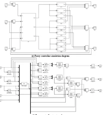
The Simulink model used for simulating the 300MW CFB boiler combustion control system is shown in Figure 6.
In the CFB boiler combustion system, in order to optimize the combustion, we need to adjust the bed temperature and bed pressure. When the given value changes, the goal of the control system is following the given value quickly and accurately.
Figures 7 and 8 presents the simulation results for increasing the given value bed pressure by 2 kPa, it can be seen that the main steam pressure fluctuations of the PID controller and fuzzy controller are small. While the PID control system bed pressure curves take more than 1000 s to get stable, the fuzzy control system bed temperature curve has been stable at about 500 s.
Figures 9 and 10 are the simulation results for the given value main steam pressure increased by 1MPa, it can be seen that the curves of fuzzy controller and PID controller are stable at about 3500 s. However, there exist overshoots in the PID controller curves. The bed pressure curve fluctuation of the fuzzy controller is less than that of PID controller. Fig. 5. The location of the quantization factor and the scaling factor
) (t x )
(x
[image:3.595.55.278.532.610.2]
[image:3.595.55.272.722.768.2]In the control system, the control action may be affected by unknown factors. In this case, the control objective of the controller is to make the control action quickly return to pre-disturbance size to minimize the impact on the controlled object.
When the bed pressure is stable, a disturbance signal of the primary air volume was issued on 2500 s, the simulated curves of the control effect and controlled variable are shown in Figures 11 and 12.
As can be seen, it takes less time for the control effect of the fuzzy controller to return to the pre-disturbance values than that of the PID controller. Therefore, the fuzzy controller has a better inherent anti-interference ability than the PID controller.
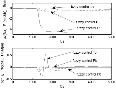
The control system will not only be affected by the disturbance from the control volume, but also be influenced by other unknown factors. In order to test the ability of resisting disturbance, a step disturbance of the slag cooler speed was issued on 1000 s. The simulation curves are shown in Figures 13 and 14.
As can be seen, the fuzzy controller can quickly eliminate the disturbance effect, and effectively limit the amplitudes of fluctuation of the controlled quantities. Therefore, the fuzzy controller has a better ability of anti-disturbance.
IV. SUMMARY
This paper describes the design of a direct type of multivariable fuzzy controller. When a given value of the system is changed, the controller can track the given value rapidly. If the control action is affected by unknown factors, the controller can make the control action return to the pre-disturbance size quickly. If the system is affected by external disturbances, the controller can adjust the control functions quickly so as to eliminate the disturbance. Hence, the designed fuzzy controller can deal with the control problem of the complex multivariable dynamic system, holding characteristics including nonlinearity, strong coupling and parameters time-varying.
TABLE Ⅱ
THE FUZZY CONTROL RULES OF BED TEMPERATURE FUZZY CONTROLLER
μv_Tb
ETb
NL NM NS ZO PS PM PL
EcTb
NL PL PL PM PS PS NS NS NM PL PL PM PS ZO NS NM NS PL PM PM PS NS NM NL ZO PL PM PS ZO NS NM NL PS PL PM PS NS NM NM NL PM PM PS ZO NS NM NL NL PL PS PS NS NS NM NL NL
TABLE Ⅲ
THE FUZZY CONTROL RULES OF BED PRESSURE FUZZY CONTROLLER
F1_Pb
EPb
NL NM NS ZO PS PM PL
EcPb
NL PL PL PL PS NS NS NM NM PL PL PL PS NS NM NL
NS PL PL PM PS NS NM NL ZO PL PL PM ZO NM NL NL PS PL PM PS NS NM NL NL PM PL PM PS NS NL NL NL PL PM PS PS NS NL NL NL
TABLE Ⅳ
THE FUZZY CONTROL RULES OF BED PRESSURE FEEDFORWARD COMPENSATION FUZZY CONTROLLER
B_Pb
EPb
NL NM NS ZO PS PM PL
EcPb
NL PL PL PM PS PS NS NS NM PL PL PM PS ZO NS NM NS PL PM PM ZO NS NM NL ZO PL PM PS ZO NS NM NL PS PL PM PS ZO NM NM NL PM PM PS ZO NS NM NL NL
PL PS PS NS NS NM NL NL
TABLE Ⅴ
THE FUZZY CONTROL RULES OF MAIN STEAM TEMPERATURE FUZZY CONTROLLER
B_P0
EP0
NL NM NS ZO PS PM PL
EcP0
NL NL NL NM NS NS PS PS NM NL NL NM NS ZO PS PM NS NL NM NM NS PS PM PL ZO NL NM NS ZO PS PM PL PS NL NM NS PS PM PM PL PM NM NS ZO PS PM PL PL PL NS NS PS PS PM PL PL
TABLE Ⅵ
THE FUZZY CONTROL RULES OF MAIN STEAM TEMPERATURE FEEDFORWARD COMPENSATION FUZZY CONTROLLER
F1_P0 NL NM NS ZO PS PM PL EF1
EcF1
NL NL NL NM NS NS PS PS NM NL NL NM NS ZO PS PM NS NL NM NM ZO PS PM PL ZO NL NM NS ZO PS PM PL PS NL NM NS ZO PM PM PL PM NM NS ZO PS PM PL PL
PL NS NS PS PS PM PL PL
TABLE Ⅶ
The functions of quantitative factors and proportional factors Ke (eTb) Kec(eTb) KTb_μv
2 2
1 0.95 eeTb 2
366
1 0.85 eeTb
0.002
1
Tbe
e
Ke(ePb) Kec(ePb) KPb_F1 KPb_B
2 6.97
1 0.9 eePb 2
815
1 0.9 eePb
0.018
1 Pb e
e e0.0035ePb 1 Ke(eP0) Kec(eP0) KP0_F1 KP0_B
2
5.5
1 0.84 eePb
2
2900
1 0.8 eePb
0.0018
1 Pb e
0 1000 2000 3000 4000 5000 -20
-10 0
T/s
、、
μν
(%
)
F
1(
km
3/
h)
B
(t
/h)
0 1000 2000 3000 4000 5000
-4 -2 0 2
T/s
℃
、、
T
b(
)
P
b(
kpa
)
P
0(
M
pa
)
fuzzy control μν
fuzzy control B fuzzy control F1
fuzzy control Pb
fuzzy control Tb fuzzy control P0
Fig. 7. Fuzzy controller output curves of bed pressure given value step change
0 1000 2000 3000 4000 5000 0
5 10 15 20
T/s
、、
μν
(%
)
F
1(
km
3/
h)
B
(t
/h
)
0 1000 2000 3000 4000 5000 0
0.5 1
T/s
℃
、、
T
b/
100
(
)
P
b(
kp
a)
P
0(
M
pa
)
fuzzy control B
fuzzy control μν
fuzzy control F1
fuzzy control Tb fuzzy control Pb fuzzy control P0
Fig. 9. Fuzzy controller output curves of main steam pressure given value step change
0 1000 2000 3000 4000 5000 -20
-10 0
T/s
、、
μν
(%
)
F
1(
km
3/
h)
B
(t
/h
0 1000 2000 3000 4000 5000 -4
-2 0 2
T/s
℃
、、
T
b()
P
b(
kp
a)P
0(
M
pa
)
PID control μν
PID control B PID control F1
PID control Pb PID control P0 PID control Tb
Fig. 8. PID controller output curves of bed pressure given value step change
0 1000 2000 3000 4000 5000 -5
0 5 10 15 20
T/s
、、
μν
(%
)
F
1(k
m
3/
h)
B
(t
/h
)
0 1000 2000 3000 4000 5000 0
0.5 1
T/s
℃
、、
T
b/
100
(
)
P
b(
kpa
)
P
0(
M
pa
)
PID control B
PID control F1 PID control μν
[image:5.595.127.472.59.444.2]PID control Tb PID control Pb PID control P0
Fig. 10. PID controller output curves of main steam pressure given value step change
(a)Fuzzy controller simulation diagram
(b)Fuzzy controller structure diagram
[image:5.595.340.502.474.599.2]0 1000 2000 3000 4000 5000 -20
-10 0
T/s
、、
μν
(%
)
F
1(
km
3/
h)
B
(t
/h
)
0 1000 2000 3000 4000 5000
-4 -2 0 2
T/s
℃
、、
T
b(
)
P
b(
kpa
)
P
0(
M
pa)
fuzzy control μν
fuzzy control B fuzzy control F1
fuzzy control Tb fuzzy control Pb
[image:6.595.316.525.68.222.2]fuzzy control P0
Fig. 11. Fuzzy controller output curves of primary air volume step disturbance
0 1000 2000 3000 4000 5000
-4 -2 0 2
T/s
、、
μν
(%
)
F
1(
km
3/
h)
B
(t
/h)
0 1000 2000 3000 4000 5000
-1 -0.5 0 0.5 1 1.5
T/s
℃
、、
T
b(
)
P
b(
kpa
)
P
0(
M
pa)
PID control Tb
PID control Pb PID control P0
PID control μν
[image:6.595.61.279.68.225.2]PID control F1 PID control B
Fig. 14. PID controller output curves of slag cooler step disturbance
0 1000 2000 3000 4000 5000 -20
-10 0
T/s
、、
μν
(%
)
F
1(
km
3/
h)
B
(t
/h)
0 1000 2000 3000 4000 5000 -4
-2 0 2
T/s
℃
、、
T
b(
)
P
b(k
pa)
P
0(
M
pa)
PID control μν
PID control F1 PID control B
PID control Tb PID control Pb PID control P0
Fig. 12. PID controller output curves of primary air volume step disturbance
REFERENCES
[1] H. Zhang, Z. S. Yue, A. D. Xu, “Analysis of Combustion Control System of 300MW Circulating Fluidized Bed Boiler,” Power System Engineering, vol. 26, no. 6, pp. 69-71, Nov. 2010.
[2] Q. Zhang, Q. H. Wang, X. L. Bai, X. H. Wang, “Control Design and Realization for Bed Temperature in Circulating Fluidized Bed Boiler Based on DMC-PID, ” Control and Instruments in Chemical Industry, vol. 36, no. 6, Jun. 2009.
[3] H. B. Yu, J. Chu, “An Expert PID Control method for level Control of CFB Boiler,” Mechanical & Electrical Engineering Magazine, vol. 17, no. 3, Mar. 2000.
[4] C. F. Wang, Y. B. Qiu, “The automatic controI system of circulatory fluidized-bed boiler based on programmable control technology,” Manufacturing Automation, vol. 31, no. 11, Sep. 2009.
[5] H. Habbi, M. Zelmat, B. O. Bouamama, “A dynamic fuzzy model for a drum-boiler-turbine system,” Automatica, vol. 39, pp. 1213-1219, Sept. 2003.
[6] K. Erkki, “Advanced control of an industrial circulating fluidized bed boiler using fuzzy logic,” Ph.D. dissertation, Dept. Process. Eng., Oulu University, Oulu, Finland, 2000.
[7] L. Yang, M. S. Xu, “Fuzzy Control for Bed Temperature Control System of Circulateion Fluidized-Bed Boilers,” Journal of Northern Jiaotong University, vol. 26, no. 6, Jun. 2002.
[8] P. Fu, X. N. Yu, H. Wang, “Research on fuzzy control algorithm for bed temperature control of circulating fluidized bed boiler,” Machine Learning and Cybernetics, vol. 2, pp. 825-828, Aug. 2005.
[9] J. Wang, C. Y. Liu, X. L. Song, Z. Y. Song, “A realization method for fuzzy decoupling control of the Circulating Fluidized Bed Boiler,” Machine Learning and Cybernetics (ICMLC), vol. 2, pp. 166-171, Jul. 2011.
[10] Q. M. Cheng, R. Q. Guo, X. F. Du, “Research on multivariable decoupling control system for combustion system of circulating Fluidized Bed Boiler,” Sustainable Power Generation and Supply, pp. 1-6, Apr. 2009.
[11] J. F. Yin, L. Liu, “Optimization of Main Steam Pressure Control System in Circulating Fluidized Bed Boiler,” Guangdong Electric Power, vol. 24, no. 10, pp. 58-65, Oct. 2011.
[12] M. Li, X. D. Xu, “Circulating fluidized bed boiler control system,” Journal of Tsinghua University (SCIENCE AND TECHNOLOGY), vol. 42, no. 5, pp. 665-668, May. 2002.
[13] J. Q. Yang, W. J. Zhao, R. Guo, W. J. Zhang, “Analysis and Design of Control Systems of Circulating Fluidized Bed Boilers,” Chinese Journal of Power Engineering, vol. 25, no. 4, pp. 517-522, Aug. 2005. [14] P. Gong, K. Zhao, J. Xiang, J. L. Yuan, “Characteristics and adjustment
methods of bed temperature for 300MWCFB boiler,” Electric Power, vol. 44, no. 3, pp. 47-51, Mar. 2011.
[15] Y. S. Hao, “Research on Modeling and Advanced Control of a Large Circulating Fluidized Bed Boiler,” Ph.D. dissertation, Dept. Environment. Energy, Southeast University, 2009.
0 1000 2000 3000 4000 5000
-4 -2 0
T/s
、、
μν
(%
)
F
1(
km
3/
h)
B
(t
/h)
0 1000 2000 3000 4000 5000
-0.5 0 0.5
T/s
℃
、、
T
b(
)
P
b(k
pa)
P
0(
M
pa)
fuzzy control Tb
fuzzy control Pb
fuzzy control P0 fuzzy control μν
fuzzy control F1 fuzzy control B
Fig. 13. Fuzzy controller output curves of slag cooler step disturbance
[image:6.595.61.274.266.423.2] [image:6.595.64.268.455.610.2]