Abstract— A method of coupled magneto-superelastic analysis by the sequential approach is proposed for shape memory alloy (SMA) helical spring actuators controlled by magnetic force. The commercial finite element software ANSYS/Emag is used for the magnetic field analysis, while the one-dimensional finite element program developed by the authors is used for the analysis of superelastic behaviors of SMA helical springs. The validity of the proposed method is verified by applying the method to the analysis of actuator models utilizing SMA composite or ferromagnetic SMA helical springs and comparing the calculated results with the experimental results.
Index Terms— Computational Mechanics, Finite Element Method, Shape Memory Alloy, Coupled Magneto-Superelastic Analysis
I. INTRODUCTION
Shape memory alloys (abbreviated as SMAs) have been attracting much attention as smart materials applicable to various fields [1]. The SMA helical springs are often used as actuator devices in recent years. Slow response is pointed out as a weakness for the actuators using thermo-reactive SMAs. To overcome such a problem, the actuators using the helical springs of SMA composites controlled by magnetic force are under development. The computational prediction of the magneto-superelastic behaviors is indispensable to the efficient and rational design of SMA helical spring actuator devices.
The authors proposed a method of finite element analysis for the superelastic, large deformation behaviors of SMA devices of one-dimensional shape such as beams and helical springs and experimentally verified the validity of the proposed method [2]-[4]. Brinson’s one-dimensional constitutive modeling [5] was extended to take account of torsional deformation. The incremental finite element method for the large deformation analysis with layered linear
Manuscript received January 7, 2008. This work was supported in part by Grant-in-Aid for JSPS fellows (16-04336) and Darpa-ONR contract (N00014-02-1-0689 and N-00014-00-1-0520) for the University of Washingon (Taya).
Y. Toi is with the Institute of Industrial Science, University of Tokyo, Komaba, Meguro-ku, Tokyo, 153-8505 Japan (phone: 03-5452-6178, fax: 03-5452-6180, e-mail: [email protected]) .
J.-B. Lee was with the Institute of Industrial Science, University of Tokyo, Komaba, Meguro-ku, Tokyo, 153-8505 Japan.
M. Taya is with the Center for Intelligent Materials and Systems, University of Washington, Seattle, WA 98195-2600, USA (e-mail:
Timoshenko beam elements was formulated by using the extended constitutive equation. The proposed method is a general-purpose computing tool for the superelastic, large deformation analysis of one-dimensional SMA devices, which can be extended to the magneto-superelastic analysis of SMA composite and ferromagnetic SMA devices.
In the magneto-superelastic analysis of SMA helical springs described in the present paper, the commercial finite element code (ANSYS/Emag) and the finite element program developed by the authors are respectively used for the magnetic and the superelastic analysis. Numerical studies are conducted for the SMA composite helical spring actuators composed of nonferromagnetic SMA (NiTi) wires and ferromagnetic metal (Fe). The validity of the proposed method is illustrated by comparing the calculated results with the experimental results given by the CIMS (Center for Intelligent Materials and Systems) at the University of Washington.
II. FINITE ELEMENT PROCEDURE FOR SUPERELASTIC ANALYSIS OF SMA HELICAL SPRINGS
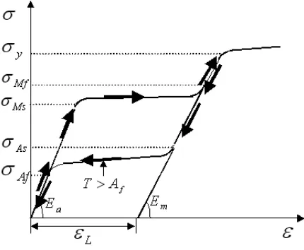
The normal stress-normal strain relation for the superelastic behavior of SMAs as shown in Fig. 1 is expressed by the following equation [5]:
(
0)
(
0)
(
0)
0=
E
−
+
Ω
S−
S+
T
−
T
−
σ
ε
ε
ξ
ξ
θ
σ
(1)where
E
; Young’s modulus,Ω
; transformation coefficient,ξ
S; stress-induced martensite volume fraction,θ
; thermal elastic coefficient,T
; temperature. The subscript ‘0’ indicates the initial values.Ω
is expressed asE
L
ε
−
=
Ω
(2) whereε
L is the maximum residual strain. Young’s modulusE
is a function of the martensite volume fractionξ
, which is given by)
(
m aa
E
E
E
E
=
+
ξ
−
(3) whereE
m andE
a are Young’s modulus of austenite phase and martensite phase respectively. The total martensite volume fractionξ
is expressed asT S
ξ
ξ
ξ
=
+
(4) whereξ
T is the temperature-induced martensite volume fraction.ξ
,ξ
S andξ
T are functions of the temperatureT
and the stressσ
. To consider the difference between tensileFinite Element Analysis of
Magneto-Superelastic Behavior of
Shape Memory Alloy Composite Actuator
and compressive behavior, von Mises equivalent stress
σ
e in the evolution equations ofξ
,ξ
S andξ
T is replaced with Drucker-Prager equivalent stressσ
eDP [6] defined asp
e DP
e
σ
β
σ
=
+
3
(5) whereβ
is the material parameter andp
is the hydrostatic pressure given by(
x y z)
p
=
σ
+
σ
+
σ
3
1
(6) In one-dimensional case, the equivalent stress in eq. (5) is expressed as
βσ
σ
σ
DP=
+
(7) The torsional behavior of SMAs, that is the shear stress-shear strain behavior due to torsion, is assumed to be qualitatively similar to, but independent of the normal stress-normal strain behavior. Accordingly, the relation between the shear stress
τ
and the shear strainγ
is expressed by the following equation:(
0)
(
0)
0
γ
γ
τξ
τξ
ττ
τ
−
=
G
−
+
Ω
s−
s(8)
The evolution equation for the martensite volume fraction
τ
ξ
s due to torsion is assumed to be similar to that due to normal deformation. The equivalent stress describing the evolution equation isZ
θ
τ
[image:2.612.77.292.461.638.2]3 . Details of the above-mentioned constitutive equation model are given by Toi et al. [2]-[4]. Although exactly, the tensile and the torsional behavior are complicatedly coupled [7], [8], the independency as mentioned above is assumed since the torsional deformation is dominant in the helical springs to be analyzed in the present study.
Fig. 1 Superelastic stress-strain behavior of SMA The followings are assumed in the finite element formulation using linear Timoshenko beam elements. The axial displacement and the torsional angle as well as the lateral deflections in two directions and the rotational angle of a cross-section are linearly interpolated in the element.
The shear strain energy term associated with bending is treated as a penalty function since the influence of bending in helical springs is much smaller than torsion. The tangent stiffness method considering two types of nonlinearities due to superelasticity and finite deformation is formulated according to the incremental theory by the total Lagrangian approach [9], in which the effect of nonlinear terms with respect to the axial displacement of a beam is neglected [10]. Details of the finite element formulation described above are given by Toi et al. [2]-[4].
The incremental stress-strain relation for the analysis of helical springs is written in the following form:
{ }
Δ
σ
=
[ ]
D
se(
{ } {
Δ
ε
−
Δ
ε
se}
)
(9)where
{ }
{ }
⎪
⎪
⎭
⎪
⎪
⎬
⎫
⎪
⎪
⎩
⎪
⎪
⎨
⎧
Δ
Δ
=
Δ
⎪
⎪
⎭
⎪
⎪
⎬
⎫
⎪
⎪
⎩
⎪
⎪
⎨
⎧
Δ
Δ
Δ
Δ
=
Δ
⎥
⎥
⎥
⎥
⎦
⎤
⎢
⎢
⎢
⎢
⎣
⎡
=
⎪
⎪
⎭
⎪
⎪
⎬
⎫
⎪
⎪
⎩
⎪
⎪
⎨
⎧
Δ
Δ
Δ
Δ
=
Δ
se se se yz xz se se se yz xzG
G
G
E
D
γ
ε
ε
γ
γ
γ
ε
ε
τ
τ
τ
σ
σ
0
0
}
{
,
,
0
0
0
0
0
0
0
0
0
0
0
0
]
[
,
(10)in which
τ
xz andτ
yz (γ
xz andγ
yz) are the shear stresses (strains) due to bending. The final form of eq. (10) is given in [2]-[4].The element stiffness equation in an incremental form is expressed as follows [2]-[4]:
[ ] [ ] [ ]
(
){ }
{ } { }
Δ
+
+
∫
[ ]
[ ]
{
Δ
}
=
Δ
+
+
e V se T R G LdV
D
B
f
f
u
k
k
k
) 0 ( 0ε
(11) where[ ]
=
∫
[ ] [ ][ ]
e V ) ( TdV
B
D
B
k
0 0 0 0 (12)[ ]
[ ] [ ][ ] [ ] [ ][ ] [ ] [ ][ ]
(
)
∫
+
+
=
e V ) ( L T L T L L T LdV
B
D
B
B
D
B
B
D
B
k
0 0 0 (13)[ ]
=
∫
[ ] [ ][ ]
e V ) ( TG
G
S
G
dV
III. MAGNETO-SUPERELASTIC ANALYSIS PROCEDURE OF SMA COMPOSITE HELICAL SPRING ACTUATORS The coupled magneto-superelastic analysis of SMA composite helical spring actuators is conducted by the sequential procedure (the staggard method or the weakly-coupled method) in which the magnetic and the superelastic analysis are conducted alternately. The commercial code [11] (ANSYS/Emag) and the superelastic, large deformation finite element analysis program of SMA helical springs developed by the authors are used for the magnetic analysis and the superelastic analysis respectively.
The sequential analysis procedure is shown in Fig. 2. The coupled analysis starts with the input of the shape information of the helical spring into the magnetic analysis code from the superelastic analysis program. The magnetic analysis code calculates and outputs the magnetic force increments acting on the helical spring, based on the shape information input. The magnetic force output is input into the superelastic program, which calculates the incremental displacements, strains and stresses. Based on the calculated displacements, the shape information of the helical spring is modified and output, which is again input into the magnetic analysis code. The superelastic, large deformation process of the SMA helical spring is simulated by conducting the above-mentioned procedure repeatedly.
ANSYS/Emag, which is a commercial software frequently used for multi-physics analysis, is employed as the magnetic analysis code [11]. The scalar potential method is employed for the magnetic analysis because of relatively easy modeling and small load on computers. Eight-node hexagonal solid elements and four-node tetrahedral elements (SOLID96) are respectively used for the magnetic body such as a helical spring and the space. Six-node triangular column elements (INFIN111) are used as infinite-boundary elements. The modeling of an electric source utilizes SOURC36. The DSP (difference scalar potential) method is used for the computation. The shape information of the helical spring calculated by the structural analysis program is input into the magnetic analysis code as the solid modeling information (key points and volume). The magnetic force increments at each node of the helical spring are output as the calculated results.
[image:3.612.320.535.49.206.2]The transformation of the input and output data between the magnetic analysis code and the superelastic analysis program is conducted in the interface program. The transformation of nodes and nodal forces is necessary as the superelastic analysis program and the magnetic analysis code use two-node straight beam elements and eight-node hexagonal solid elements, respectively. The control program runs the magnetic analysis code, the superelastic analysis program and the interface program sequentially, managing the calculated values of loads, displacements, strains and stresses. The total modeling and analysis are done by batch processing.
Fig. 2 Coupled magneto-superelastic analysis
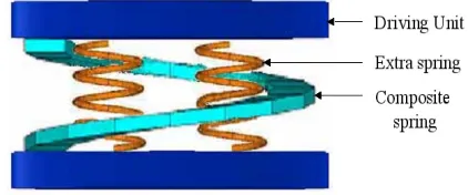
IV. RESULTS OF MAGNETO-SUPERELASTIC ANALYSIS OF SMA COMPOSITE HELICAL SPRING ACTUATORS The magneto-superelastic, large deformation behavior of the SMA composite helical spring actuator is analyzed. The SMA composite helical spring actuator is composed of a pair of driving units, a SMA composite helical spring and two extra SMA helical springs as shown in Fig. 3. The composite helical spring elongated downward by the weight of 2.5N is compressed upward by the magnetic force from the driving units.
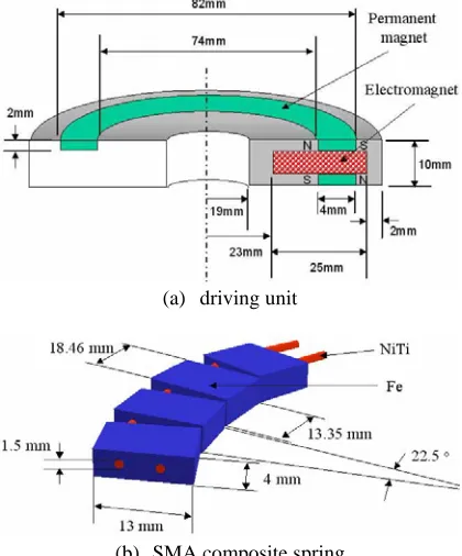
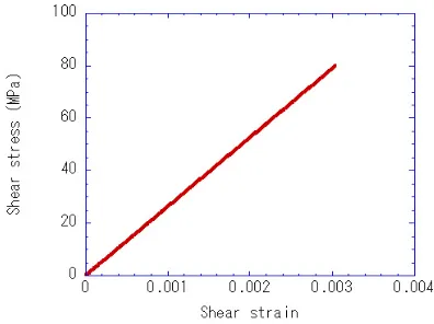
Fig. 4 is a sketch of the driving unit and the composite helical spring. The driving unit is composed of a hybrid reluctance magnet [12] combining a permanent magnet with an electromagnet as shown in Fig. 4(a). The permanent magnet is neodymium 35 with the specific magnetic permeability of 1.17 and the retentivity of 835,563A/m. The electric current of 0~6A flows through the electromagnet coil with 264 turns. The composite helical spring is composed of two SMA (NiTi) wires and 16 ferromagnetic (Fe) blocks. The magnetic permeability
μ
(B
=
μ
H
,B
; magnetic density,H
; magnetic intensity) of Fe is shown in Fig. 5. The magnetic control of the nonferromagnetic SMA helical spring becomes possible by such composition. The material constants of NiTi are shown in Table 1. The extra helical spring with the outer radius of 10mm and the total length of 14mm is composed of a NiTi wire with the diameter of 1mm. The extra helical springs are neglected in the magnetic analysis as the magnetic permeability of NiTi is small. [image:3.612.324.535.598.686.2](a) driving unit
[image:4.612.80.290.50.303.2](b) SMA composite spring
Fig. 4 Driving unit and SMA composite spring
0 0.5 1 1.5 2
0 2000 4000 6000 8000
B (T)
[image:4.612.325.527.251.402.2]H (A/m)
[image:4.612.91.276.347.493.2]Fig. 5 B-H curve for Fe Table 1 Material constants for NiTi Young’s modulus of
austenite phase
E
a=
70000
[MPa]
Young’s modulus of
martensite phase
E
m=
33000
[MPa]
starting stress for martensite
transformation
σ
Ms=
427
.
8
[MPa]
finishing stress for martensite
transformation
σ
Mf=
542
.
8
[MPa]
starting stress for austenitetransformation
σ
As=
210
.
5
[MPa]
finishing stress for austenite
transformation
σ
Af=
110
.
4
[MPa]
residual normal strainε
L=
0
.
047
residual shear strain
γ
L=
0
.
047
material parameterβ
=
0
.
15
Fig. 6 shows the calculated and experimental results for the relation between the distance from the upper to the lower driving unit and the electric current. The composite helical spring elongates to 28mm by the initial weight loading and is fully compressed by the electric current of 6A. The calculated results are in good agreement with the experimental results given by the CIMS of the University of Washington. Fig. 7 shows the deformation profiles of the composite helical spring with the variation of electric current. Fig. 8 shows the shear stress-shear strain curve of the NiTi wire in the composite helical spring, which exhibits linear, elastic behavior. Fig. 9 is the deformation process of the extra helical spring. It is seen from the shear stress-shear strain curve in Fig. 10 that the martensite transformation takes place in the spring during the tensile process under the initial loading, exhibiting the superelastic behavior.
Fig. 6 Current-displacement curve for SMA composite spring actuator
0A 1A
2A 3A
4A 6A
[image:4.612.341.510.475.685.2] [image:4.612.75.295.532.737.2]Fig. 8 Shear stress-shear strain curve for NiTi wire in composite spring
Fig. 9 Deformation of extra spring
Fig. 10 Shear stress-shear strain curve for extra spring The number of finite elements for the magnetic analysis is 91,864 to 217,053 (30,242~51,036 nodes), while 64 (65 nodes) for the superelastic analysis. The total number of incremental steps for the superelastic analysis is 700, while
the magnetic analysis is conducted at every 100 steps.
V. CONCLUSION
In the present study, the finite element procedure for the superelastic, large deformation behavior of SMA devices of one-dimensional shape previously proposed by the authors has been extended to the magneto-superelastic analysis of SMA composite helical spring actuators. The magneto-superelastic analysis system has been developed for the SMA composite helical spring actuators, which employs the sequential method combining the magnetic analysis by the commercial code ANSYS/Emag with the superelastic, large deformation analysis of SMA devices by the finite element program developed by the authors. The magnetic analysis of SMA composite actuators is based on the exact shape modeling of the helical springs. The validity of the proposed analysis system as a simulation tool for the design of SMA actuators has been illustrated by comparing the calculated results with the experimental results given by the CIMS of the University of Washington.
REFERENCES
[1] H. Hosoda, and S. Miyazaki, “Recent Topics of Shape Memory Materials and Related Technology,” Journal of the Japan Society of
Mechanical Engineers, Vol. 107, No. 1028, 2004, pp. 509-515.
[2] Y. Toi, J.-B. Lee and M. Taya, “Finite Element Analysis of Superelastic Behavior of Shape memory alloy Devices (1st Report, Small Deformation Analysis of Tensile and Bending Behaviors),”
Transaction of the Japan Society of Mechanical Engineers, Series A,
Vol. 68, No. 676, 2002, pp. 1688-1694.
[3] Y. Toi, J.-B. Lee and M. Taya, “Finite Element Analysis of Superelastic Behavior of Shape Memory alloy Devices (2nd Finite Deformation Analysis of Beams and Helical Springs),” Transaction of the Japan Siciety of Mechanical Engineers, Series A, Vol. 68, No. 676, 2002, pp. 1695-1701.
[4] Y. Toi, J.^B. Lee and M. Taya, “Finite Element Analysis of Superelastic, Large Deformation Behavior of Shape Memory Alloy Helical Springs,” Computers and Structures, Vol. 82, No. 20/21, 2004, pp. 1685-1693.
[5] L. C. Brinson, “One Dimensional Constitutive Behavior of Shape Memory Alloys: Thermomechanical Derivation with Non-Constant Material Functions and Redefined Martensite Internal Variable,” Journal of Intelligent Material Systems and Structures, Vol. 4, 1993, pp. 229-242.
[6] F. Auricchio and R. L. Taylor, “Shape Memory Alloy: Modeling and Numerical Simulations of the Finite-Strain Superelastic Behavior,”
Computer Methods in Applied Mechanics and Engineering, Vol. 143,
1997, pp. 175-194.
[7] M. Tokuda and M. Sittner, “Multi-Axial Constitutive Equations of Polycrystalline Shape Memory Alloy (1st Report, Modeling and Formulation),” Transactions of the Japan Society of Mechanical Engineers, Series A, Vol. 65, No. 631, 1999, pp. 491-497.
[8] Q. P. Sun and Z. Q. Li “Phase Transformation in Superelastic NiTi Polycrystalline Micro-Tubes under Tension and Torsion: from Localization to Homogeneous Deformation”, International Journal of Solids and Structures, Vol. 39, 2002, pp. 3797-3809.
[9] The Japan Society of Mechanical Engineers ed., JSME Computational Mechanics Handbook (Vol. 1, Finite Element Method: Structure), The Japan Society of Mechanical Engineers, 1998, pp. 101-124. [10] T. Kawai, Analysis of Buckling Problem, Baifukan, 1974, pp. 75-87. [11] ANSYS, Inc., ANSYS Seminar Note: Emag, Cybernet Systems Co. Ltd.,
2001.
[image:5.612.107.265.258.511.2]