Abstract—Cancellous bone possesses a complicated structure of beam and plate-like elements whose architecture depends on the specific tissue and physiology of the individual. Classical, Voxel-based modelling is computation intensive and thus sub-optimal for parametric studies. Therefore, synthetic 2D-microstructures, based on sections of cancellous bone were generated and the effect of local architecture (vertebra and femur), bone density and loss of connectivity was researched by varying the parameters of the model. It was demonstrated that the use of bone density as a sole parameter induces considerable uncertainty on the assessment of the rigidity and resistance of the tissue under consideration.
Index Terms—Bone architecture, Cancellous bone, Density, Mechanical properties, Voronoi cells.
I. INTRODUCTION
Cancellous bone is formed by a complex three-dimensional structure of elements called “trabeculae” [1]-[3], which, form the viewpoint of a structural engineer could be compared to complex-shaped plates or beams. Found in the epiphysis of long bones (e.g. femur and tibia) and the centre of compact bone (e.g. vertebra), it fulfils both a structural and a physiological function [1]-[5].
The present paper focuses on the structural function of trabecular bone alone. While the compact bone which forms the exterior part of all skeletal elements represents 80% of all the bone mass in the human body and is considerably stronger than the cancellous bone, there are several reasons to investigate the latter.
First, the structure of compact bone is relatively simple compared to the architecture of cancellous bone, so its constitutive behaviour can be reasonably modelled as a homogeneous anisotropic solid under elastic, viscoelastic or elasto-viscoplastic assumptions, depending on loading conditions [2],[3],[6]-[8]. Research is then focused on the determination of the corresponding material properties as a function of physiology and pathology of a patient or population. Cancellous bone, strictly spoken, is not a material but a structure. Its behaviour depends on morphology and composition, which in turn depend on the
Manuscript received March 22, 2010. This work was supported by the Dirección General de Asuntos del Personal Académico, UNAM, under grants IN113209-3 and PE104109.
All authors are with the department of Materials and Manufacturing, DIMEI, Universidad Nacional Autónoma de México, 04510 Coyoacán, México DF. Corresponding author: R.S. phone: +52 55 56 22 80 57; fax: +52 55 56 22 80 58; e-mail: [email protected]
physiology and loading history of the specific bone in the skeletal system as well as on the health and age of the individual [1]-[5]. Material models which allow a description of the mechanical response of such a varied and complex structure in terms of continuum mechanics are still relatively underdeveloped.
Second, cancellous bone is physiologically more active than compact bone and is constantly resorbed (by osteoclasts) and regenerated (by the osteoblasts) under influence of physiological processes and applied load [9]-[11]. An unbalance between resorption and regeneration leads to osteoporosis and related pathologies, which are of increasing concern in an aging population.
Third, the mechanical function of cancellous bone can be of mayor importance under certain specific conditions. This is the case of vertebrae, which derive a significant part of their shock-absorbing capacity from the trabecular tissue [12],[13]. Also, during application of prostheses, such as pedicle screws for lumbar fixture or hip implants, the mechanical interaction between implant and tissue takes place in large part or even predominantly at the level of the cancellous bone [14]-[16]. Prediction of such interaction, from the viewpoint of mechanical reliability, is on of the long-term goals of the research in which the present work is situated.
The remainder of this text is organised as follows: first, a brief review will be presented on existing modelling strategies for the mechanical response of trabecular bone and a justification will be made for the simplifications used in the actual study. Then, the main features of the present modelling strategy will be explained. Results are presented for two distinct bone architectures in terms of stiffness, stress distribution and the effects of bone loss and connectivity loss. It must be clearly stated at this point that the goal of the present stage of the investigation is to establish methods and procedures. More specifically, the present 2D-models are used to explore the necessary features to be incorporated in future 3D-models. The results of this work will be discussed within this framework.
II. MECHANICAL MODELS FOR CANCELLOUS BONE
Although some early models for the constitutive behaviour of cancellous bone [17] were based on the theory of porous media [18],[19], it is now generally accepted that a description in terms of a cellular solid [20],[21] provides a better approximation. Early models in this field studied regular arrays of beam and plate elements which can be
Analysis of the Architecture and Mechanical
Properties of Cancellous Bone Using 2D Voronoi
Cell Based Models
analysed in good approximation with calculations from the field of solid mechanics [21],[22] or applied finite-element methods to a regular array of more or less complex cells [2],[23]. More recently, efforts have been made to model irregular cellular solids [24]-[26] using cells defined by means of Voronoi-tesselation. Although the latter studies are not explicitly related to bone tissue, the connection is easy to make, as will be illustrated in section III of this paper.
Doubtlessly, the most sophisticated approach to the modelling of the trabecular bone structure is based on microtomographic methods. X-ray tomography [27],[28] (Micro-CT) and magnetic resonance imaging [29],[30] (MRI) provide a spatial resolution which allows the analysis of the three-dimensional structure of cancellous bone into great detail. The three-dimensional information obtained is typically presented on a “Voxel”-grid, which provides the quantitative information on signal intensity within a small rectangular box in the sample. After adequate filtering, in a similar way as done by image processing on two-dimensional bitmaps, each voxel is assigned either to the bone tissue or to the open space between the trabeculae.
The three-dimensional information obtained is then typically assigned to a finite-element program, which, in its simplest form, assigns one element to each voxel belonging to the tissue. In more recent implementations, additional surface smoothing can be applied and techniques have been designed to reduce the amount of elements in the 3D models by mesh optimisation procedures [31]-[36].
The voxel-based micro finite element method (micro-FE) can be considered as the Holy Grail of research in the biomechanics of trabecular bone. This goal being reached more than one decade ago, one can righteously question the wisdom of going back to simplified models for cellular solids based on the Voronoi-tesselation as proposed here. The reason for taking such a step back is the fact that the huge benifits of microtomograpy and micro-FE come at a considerable cost. Accurate representation of the voxel-based 3D microstructure often requires several millions of elements. This results in large calculation times for the micro-FE model and considerable computing resources. Micro-CT generally relies on a synchrotron source, while the high resolution required for micro-FE results in long measuring times in MRI.
For advanced research in highly specialised centres, none of the former arguments can be considered critical and microtomography combined with micro-FE will probably remain the tool of choice in the foreseeable future. However, if clinical applications are envisioned, one must limit the use of resources to what is routinely available in a well equipped hospital and reduce measuring and calculation times to what can reasonably be assigned to a single patient in pre-treatment or pre-operational assessment or during post-treatment follow-up.
Also, if one wants to test the influence of a number morphological or constitutive parameters, it can be advantageous to use a method which can generate “synthetic” microstructures and provide a short calculation time, in order to be able to vary a large number of parameters in a controlled way, in what then could be labelled as a series of “virtual” mechanical tests. The need for real specimens, obtained
post-mortem or measured non-invasively on live beings can be greatly reduced by this approach and the statistical spread characteristic for biological tissues eliminated or even recreated by careful choice of the modelling parameters.
III. MODELLING PROCEDURE
The goal of the work is to develop a method, which, once sufficiently refined, can be used for detailed studies of specific tissues of medical interest. During the development, the exact history of the tissue is of lesser importance and it was decided to base the analysis of two samples of bovine bone, one taken from a lumbar vertebra and a second from the epiphysis of the femur. Plane sections were produced and observed by standard light microscopy. The microstructure was reproduced by stitching a considerable number of single images together as can be seen in Fig. 1a for the sample of the femur. Proceedings for the vertebral sample are identical.
Based on the sectional microstructure, one could define the boundaries of the solid parts and transform them into a line drawing to be fed into a finite-element program and perform automatic meshing on a 2D model. However, in 3D, this would be analogous to the micro-FE approach. To explore the capabilities of Voronoi-tesselation [37], the approximate centres of the pores in the microstructure were determined, assigning, on occasions, two centres to a single pore where it was clear that a connecting trabecula was originally present just outside the plane of view. The centres of the pores were then used as the forming points of a 2D Voronoi partition of the area sampled. This partition consists of a space-filling collection of polygons. Within each polygon, each point is closer to the forming point of the corresponding cell than to any other forming point. Commercial mathematical software can be used to perform this partition efficiently, based on a list of forming point co-ordinates only (Fig 2b).
In most studies on Voronoi-cell based modelling of cellular solids [24]-[26],[38]-[44], including ongoing work on 3D-modelling by the present authors, beam elements for finite element analysis are defined directly from the boundaries between the cells. Such elements are computationally efficient but introducing failure modes such as elasto-plastic transition or buckling is not self-evident [45] and of limited availability in commercial finite element software. Detailed analysis of the non-linear behaviour also means that a single beam is generally modelled by a several individual beam elements.
This procedure sacrifices part of the computational efficiency associated to the use of beam elements, but for the results shown in the following section, computation time is not a big issue on a standard up-to-date PC. For 3D analyses, this point may become significantly more important and remains to be studied. The advantage of using standard triangular elements is that most conventional constitutive laws can be implemented by built-in models in the software, analysis of buckling as a separate phenomenon is eliminated and self-contact of the structure can be introduced without additional programming effort.
In the following, only compression of the synthetic microstructure will be studied by applying a vertical displacement equal to 5% to the microstructure which represents an area of 20×33 (mm2). The sum of the reaction forces of all nodes at the model boundary is the force needed to compress the material. Young’s modulus for the solid material representing the trabeculae was set to a constant value of 392 MPa and Poisson’s coefficient taken equal to 0.3. It shall be noted that no effort was made to enforce periodic boundary conditions. This is justified by the fact that the dimensions used in the model are representative of experimental compression samples and it is known that free boundary effects affect the experimental results [46].
The response value of interest, for linearly elastic models, would be the apparent Young’s modulus of the structure, defined as the total reaction force per unit area divided by the strain (5%). However, in a plane-strain finite element model, all elements have unit thickness (i.e. 1 mm for the present case). To determine the apparent modulus, one then has to define an effective transverse section of the structure, which is equal to the width of the model multiplied by the thickness (1 mm) and divided by the area fraction of solid matter in a section perpendicular to the compression direction. Even so, the rigidity of a plane model is expected to be slightly higher than in a 3D simulation, because in the 2D model, the beams are perfectly vertical in the third dimension and thus more favourably oriented to resist compression as compared to inclined beams.
IV. SIMULATIONS AND RESULTS
Two series of basic simulations will be presented here. The first one researches the effect of area fraction (which is equal to volume fraction in good approximation [47]). The parameter which is varied is not directly the area fraction of trabeculae, but their thickness. Because thicker trabeculae have more overlap between each other, there is no linear relationship between area fraction and trabecual thickness in the present approach, as would be the case for one-dimensional beam elements in which it is rather difficult to take overlap into account. Examples of the finite element results are presented for the case of femur (Fig. 2, corresponding to the microstructure of Fig. 1.) and Vertebra (Fig. 3). In Fig. 4, the apparent Young’s modulus is presented as a function of area fraction for both microstructures.
The second series of simulations focuses on the loss of trabeculae in the microstructure. To model this effect, the trabeculae are removed in fixed amounts corresponding to 2% of the trabeculae in the original structure in four
consecutive steps (resulting in a loss of 8% of trabeculae in the final step). This procedure means that trabeculae removed in a previous step do not reappear in the next one and so simulates a gradual degradation of bone quality. Two examples of the stress distribution in the degraded structure are presented in Fig.5.
The incremental removal of trabeculae up to 8% defines a single run. If the run is repeated from the same starting structure but for different, randomly selected trabeculae, then different results are obtained. This is true both for the stiffness of the degraded structure as for the area fraction obtained, because sometimes large trabeculae are removed and sometimes smaller ones, while also de degree of overlap may vary. The stochastic effect introduced by this procedure can be characterised by executing a large number of runs. As an example, the results of two such runs are summarised in Fig. 6.
V. DISCUSSION
The modelling approach presented in this paper is in many aspects similar to other Voronoi-cell based 2D-models and several of the conclusions of earlier papers [39]-[41],[44] are clearly reproduced. The strong influence of the loss of connecting beams compared to the more gradual decrease of stiffness with the reduction of beam thickness is a clear example. Also the appearance of “high stress pathways” or connected zones of stiffer structure along which the stresses are preferentially transmitted can be observed from the individual FE-simulations. The formation of these pathways appears to be a consequence of the statistical dispersion of material properties, as they have also been seen by the authors in unrelated work on metal-metal composites [48], where the microstructural irregularity produces similar effects.
There are two aspects in the present results that are clearly different from the works cited earlier and that need some discussion. First, the use of a Voronoi grid based on measured microstructures must be critically analysed. Next, the subdivision of the beams (expanded edges of the Voronoi-cells) into triangular elements must be evaluated.
random procedure, while the meshes for the vertebra are similar to the ones that can be generated by perturbating a rectangular grid.
The difference between both models is illustrated in Fig. 4. The trabeculae of the synthetic structure based on the microstructure of the vertebra are oriented principally in the
direction of compression and consequently provide enhanced stiffness in this direction, as compared to the more randomly oriented trabeculae of the femur-based synthetic structure. However, structures like the ones in Fig. 3 have a significantly lower shear modulus than the ones in Fig. 2 [49].
[image:4.595.308.547.124.319.2]Fig. 1. a) Original microstructure obtained by stitching together several optical microscopy image. b) Forming points and the corresponding Voronoi partition of a part of the zone of interest. c) Reconstructed, synthetic microstructure.
Fig. 3. Stress distribution in a synthetic microstructure based on the forming points obtained from a micrograph of trabecular bone from bovine vertebra. a) Corresponds to an area fraction of 30%, b) to 70%.
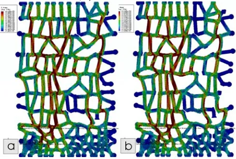
Fig. 5. Stress fields in the synthetic structures based on vertebral tissue, with 4 and 8% loss of trabeculae by number. The random assignment of the eliminated trabeculae converts
[image:4.595.46.288.128.301.2]the area fraction and stiffness into random variables (Fig. 6).
[image:4.595.307.548.372.529.2]Fig. 2. Stress distribution in a synthetic microstructure based on the forming points obtained from a micrograph of trabecular bone from bovine femur. a) Corresponds to an area fraction of 40%, b) to 76%.vertebral tissue.
Fig. 4. Apparent Young’s modulus as a function of area fraction occupied by trabeculae for vertebra and femur.
[image:4.595.48.289.374.532.2] [image:4.595.47.291.581.745.2] [image:4.595.306.548.582.742.2]of 2% (by number) up to 8%; the difference in size and overlap for the randomly chosen trabeculae implies that the
loss of area fraction and loss of stiffness become random variables.
The use of standard triangular elements for the meshing of the synthetic microstructure is not entirely desirable as it disposes of the numerical efficiency inherent to the use of beam elements. In fact, if the original microstructure were used with this meshing method, one would be working on a two-dimensional micro-FE method. The reason for using standard elements was convenience. Beam elements available in commercial software packages do not always posses the features needed for the advanced modelling of elastic or plastic buckling or mutual contact. By subdividing each trabecula into many small elements, the buckling problem is effectively avoided, because the irregularity of the structure ensures that bending moments are always present in each beam and buckling becomes a gradual process instead of a sudden reaction to energetic instability. Also the effect of geometric non-linearity is largely solved by the use of small elemens.
Mutual contact for standard elements was available as an option in the software package used and is important for the dense part of the synthetic structures presented. Except for the densest microstructures, mutual beam contact is probably of minor concern in three-dimensional structures and therefore can be neglected initially in future analyses. The mayor concern will be the development of reliable 3D nonlinear elements which reproduce the failure modes in a physically sensible way. For the 2D-approximation, the additional calculation time inherent to using a fine mesh of standard elements is largely offset by the simplicity of implementation in the model. The use of standard non-linear constitutive equations for this kind of elements is routine and will be investigated in future work.
A final note must be made about the relevance of this kind of studies for “true” biomechanics. The methods presented here, as is the case for all Voronoi-cell based models published to date, can be validated only by extensive comparison to experimental results. The contribution of studies like the present one lays in the identification of the critical aspects to be addressed in future, more precise modelling.
In spite of this, the results show good qualitative agreement with established facts about the biomechanics of trabecular bone. If one considers the loss of trabecular bone section compared to the loss of tissue connectivity, it is clearly seen that the latter condition is more critical. The loss of 2% of trabecula in cancellous bone corresponds to what is measured as the annual loss in early post-menopausal women [50]. The predicted loss of 30% in rigidity after 4 years is an overestimation, because in living tissue, the trabeculae which carry the smallest load are the first to dissapear, while the enhanced load on the remaining trabeculae will slow the degrading effects of desequilibrium between osteogenesis and bone loss on the high stress pathways [10]-[11]; the random removal of trabeculae used in most Voronoi-cell based approaches fails to take into account this biologically regulated selection.
Also the difference in behaviour of the vertebra-based synthetic structure and the femur-based one are consistent to what can be expected. Even if it is not easy to visually
associate the Voronoi-based network to the original micrograph, the higher compression resistance of the vertebral tissue is a logical result, because even if bovines don’t walk upright, the bending load on the vertebral column produces longitudinal loads on the individual vertebrae. For the epiphysis of the femur, which acts as a pivot point, one cannot predict a unique load condition and uniaxial strength is sacrificed to provide isotropic rigidity. The synthetic microstructures reproduce this tendency in a satisfactory manner.
VI. CONCLUSION
A highly simplified way for modelling the mechanical response of an experimentally observed cancellous bone microstructure was presented with the main goal of investigating the feasibility of using a Voronoi-cell based synthetic microstructure as a substitute for the original. Such substitution allows for easy and efficient parametric studies of the mechanical properties of trabecular bone.
The fine meshing technique used for the 2D models is likely to be computationally inefficient in 3D applications but shows certain advantages in terms of flexibility and implementation compared to the use of beam elements in 2D. The data for mechanical properties calculated for synthetic microstructures were not directly compared to experimentally calculated data but were consistent with the expected behaviour of the tissues that were analysed.
The need for using data of the real architecture of the tissue studied in producing the synthetic microstructure was illustrated by the marked differences between models based on vertebra and femur. These differences clearly show that bone density alone cannot be used to asses tissue quality if tissues with distinct architectures are to be compared.
ACKNOWLEDGMENT
We would like to thank G. Álvarez, I. Cueva and E. Ramos for technical assistance during the elaboration of this study.
REFERENCES
[1] X. J. Li, W. S. S. Jee, ”Integrated bone tissue anatonomy and physiology,” in Current topics in Bone Biology, H. W. Deng, Y. Z. Liu, C. J. Guo and D. Chen Ed. New York: World Cientific, 2005, pp. 11-56.
[2] S. C. Cowin, Bone mechanics Handbook. Boca Ratón, FL: CRC Press,
2001.
[3] J. Currey, Bones: Structure and Mechanics, Princeton, NJ: Princeton
University Press, 1984.
[4] T. M. Keaveny, E. F. Morgan,.G. L. Niebur and O. C. Yeh, “Biomechanics of trabecular bone” Ann. Rev. Biomedical Eng, vol 3, 2001, pp 307-333.
[5] J. L. Gibson, “The mechanical behaviour of cancellous bone”, Journal of Biomechanics, Vol 18, May 1985, pp. 317-328.
[6] J. D. Currey, “The effect of porosity and mineral content on the Young's modulus of elasticity of compact bone”, Journal of Biomechanics, Vol. 21, Feb. 1988, pp. 131-139.
[7] J. D. Currey “Physical characteristics affecting the tensile failure properties of compact bone”, Journal of Biomechanics, Vol 23, Aug., 1990, pp 837-844
[8] H. H. Bayraktar and E. F. Morgan “Comparison of the elastic and yield properties of human femoral trabecular and cortical bone tissue”,
[9] D. R. Carter, M .C. H. Van der Meulen, G. S. Beaupré, “Mechanical factors in bone growth and development”, Bone, Vol 18, Supplement 1,
Jan. 1996, pp. S5-S10.
[10] R. B. Martin, “Toward a unifying theory of bone remodeling”, Bone, Vol. 26, Jan. 2000, pp. 1-6.
[11] R. Huiskes, R. G. Ruimerman, H. van Lenthe and J. D. Janssen, “Effects of mechanical forces on maintenance and adaptation of form in trabecular bone”. Nature 405, 2000, 704-706.
[12] T. M. Keaveny, J. M. Buckley, “Biomechanics of Vertebral Bone”, in
Spine Technology Handbook, S. M. Kurtz and A. A. Edidin, ed.
Maryland Heights, Mo: Academic Press 2006, pp 63-98.
[13] K. S. Jensen, L. Mosekilde and L. Mosekilde, “A model of vertebral trabecular bone architecture and its mechanical properties” Bone, vol 11, Jun. 1990, pp. 417-423.
[14] B. E. McKoy, Y. H. An and R. J. Friedman, “Factors affecting the strength of bone-implant interface”, In Mechanical Testing of Bone and Bone-Implant Interface. Y. H. An and R. A. Draughn ed. Boca Ratón,
FL: CRC Press, 1999, pp 439-463.
[15] M. A. Ritter, J. D. Lutring, M. E. Berend, and J. L. Pierson, “Failure Mechanisms of total hip replacement”. Clin. Orthop. Relat. Res. vol. 453, 2006 pp. 110-114.
[16] K. L. Ong, S. M. Kurtz, M. T. Manley, N. Rushton, N. A. Mohamed and R. E. Field. “Biomechanics of the Birmingham hips resurfacing arthroplasty” J. Bone Joint Surg. Br. vol. 88B, 2006, pp. 110-115.
[17] D. R. Carter and W. C. Hayes, “The compressive behaviour of bone as a two-phase porous structure”, J. Bone Joint Surg. Am. vol. 59, 1977, pp. 954-962.
[18] F. Gassmann, “Über die elastizität poröser medien” Viertel. Naturforsch. Ges. Zürich, Vol 96, 1951, pp. 1-23.
[19] M. A. Biot, “Mechanics of deformation and acoustic propagation in porous media”, J. App. Physics, vol 33, 1962, pp. 1482-1498.
[20] M. F. Asby, “The mechanical properties of cellular solids”. Metall. trans. A, vol. 14, Sep. 1983, pp. 1755-1769.
[21] L. J. Gibson, M. F. Ashby, Cellular Solids: Structure and Properties. Cabridge, GB: Cambridge University Press 1999.
[22] M. J. Silva and L. J. Gibson, “Modeling the Mechanical Behavior of Vertebral Trabecular Bone: Effects of Age-Related Changes in Microstructure”, Bone, vol 21, Aug. 1997, pp.191-199.
[23] J. Kowalczyk, “Elastic properties of cancellous bone derived from finite element models of parameterized microstructure cells”, Journal of Biomechanics, vol 36 Jul. 2003, pp. 961-972.
[24] Y. X. Gan, C. Chen and Y. P. Shen, “ Three-dimensional modeling of the mechanical property of linearly elastic open cell foams”. Int. J. Solids Struct. vol. 42, 2005, pp. 6628–6642.
[25] J. S. Huang, and L.J. Gibson, “Creep of open-cell Voronoi foams”,
Mater. Sci. Eng. A, vol. A339, 2003, pp. 220-226.
[26] V. Shulmeister, M. W. D. Van der Burg, E. Van der Giessen and R. Marissen, “A numerical study of large deformations of low-density elastomeric open-cell foams”, Mechanics of Materials, 30, Oct. 1998,
pp. 125-140.
[27] U. Bonse and F. Busch, “X-ray computed microtomography (μCT) using synchrotron radiation (SR)”, Prog. Biophys. Mol. Biol., vol 65, 1996, pp. 133-169.
[28] A. Odgaard, “Three-dimensional methods for quantification of cancellous bone architecture”, Bone, vol 20, Ap. 1997, Pages 315-328.
[29] S. Majumdar, D. Newitt, M. Jergas, A. Gies, E. Chiu, D. Osman, J. Keltner, K. Keyak and H. Genant, “Evaluation of technical factors affecting the quantification of trabecular bone structure using magnetic resonance imaging” Bone, vol. 17, Oct. 1995, pp. 417-430.
[30] H. Xu, S. F. Othman and R. L. Magin,Monitoring, “Tissue Engineering Using Magnetic Resonance Imaging”, Journal of Bioscience and Bioengineering, vol. 106, Dec. 2008, pp. 515-527.
[31] B. Van Rietbergen, H. Weinans, R. Huiskes and A. Odgaard, “A new method to determine trabecular bone elastic properties and loading using micromechanical finite-element models”. Journal of biomechanics, vol. 28, 1995 pp. 69-81.
[32] T. Uchiyama, T. Tanizawa, H. Muramatsu, N. Endo , H. E.Takahashi and T. Hara, “Three-dimensional microstructural analysis of human trabecular bone in relation to its mechanical properties”, Bone, vol 25
1999, pp. 487-491.
[33] B. Van Rietbergen, S. Majumdar, D. Newitt and B.MacDonald, “High-resolution MRI and micro-FE for the evaluation of changes in bone mechanical properties during longitudinal clinical trials: application to calcaneal bone in postmenopausal women after one year of idoxifene treatment”, Clinical Biomechanics, vol. 17 Feb. 2002, pp 81-88.
[34] E. Verhulp, B. van Rietbergen and R. Huiskes, “Comparison of micro-level and continuum-level voxel models of the proximal femur”,
Journal of Biomechanics, vol 39, 2006, Pages 2951-2957
[35] R. Akhtar, S. J. Eichhorn and P. M. Mummery, “Microstructure-based Finite Element Modelling and Characterisation of Bovine Trabecular Bone”, Journal of Bionic Engineering, vol 3, Mar. 2006, pp. 3-9.
[36] D. H. Pahr and P. K. Zysset, “A comparison of enhanced continuum FE with micro FE models of human vertebral bodies”, Journal of Biomechanics, vol. 42, 2009, pp. 455-462.
[37] G. Voronoi “ Nouvelles applications des paramètres continus à la théorie des formes quadratiques”. Zeitschrift für die Reine und Angewandte Mathematik, vol. 133 1907, pp. 97-178. [38] M. J. Silva, and L. J. Gibson, “The effects of non-periodical
microstructure and defects and defects on the compressive strength of two-dimensional cellular solids”, Int. J. Mech. Sci. vol. 39, Mar. 1997,
pp. 554-563.
[39] G. Schaffner, X. D. E. Guo, M. J. Silva, L. J. Gibson, “Modelling fatigue damage accumulation in two-dimensional Voronoi honeycombs” Int. J. Mech. Sci. vol. 42, Apr. 2000, pp. 645-656. [40] H. X. Zhu, J. R. Hobdell, and A.H. Windle, “Effects of cell irregularity
on the elastic properties of 2D Voronoi honeycombs”, J. Mech. Phys. Solids, vol. 49, 2001, pp. 857 – 870.
[41] H. X. Zhu, A. H. Windle, “Effects of cell irregularity on the high strain compression of open-cell foams”, Acta Mater. vol 50, 2002, pp.
1041–1052.
[42] Y.X. Gan, C. Chen *, Y.P. Shen Three-dimensional modeling of the mechanical property of linearly elastic open cell foams International Journal of Solids and Structures 42 (2005) 6628–6642
[43] Y. X. Gan, C. Chen and Y. P. Shen, “Three-dimensional modeling of the mechanical property of linearly elastic open cell foams” Int. J. Solids Struct. vol. 42, 2005, pp. 6628–6642.
[44] H. X. Zhu, S. M. Thorpe and A. H. Windle, “The effect of cell irregularity on the high strain compression of 2D Voronoi honeycombs”, Int. J. Solids Struct. vol. 43, 2006, pp. 1061–1078. [45] J. Dujc, B. Brank and A. Ibrahimbegovic, “Multi-scale computational
model for failure analysis of metal frames that includes softening and local buckling”, Comput. Methods Appl. Mech. Engrg. , vol 21-22, Apr. 2010, pp. 1371-1385.
[46] T. M. Keaveny, R. E. Borchers, L. J. Gibson and W. C. Hayes, “Trabecular bone modulus and strength can depend on specimen geometry”, Journal of Biomechanics, vol. 26, Aug. 1993, pp. 991-995. [47] E. E. Underwood, Quantitative Stereology, Reading, MA:
Addison-Wesley 1970.
[48] R. Schouwenaars, V H. Jacobo, S.M. Cerrud and A. Ortiz: “Finite element simulation of microstresses in a traditional FGM: the case of soft tribo-alloys”, Mater. Sci. Forum, vol. 492-493, 2005, pp. 421-426.
[49] H. R. López and E. I. Bustillo. Análisis in-silico de las propiedades mecánicas del hueso esponjoso mediante la técnica de celdas de Voronoi, Graduate thesis, Universidad Nacional Autónoma de México, 2008.
[50] R. McCalden, J. McGeough and C. M. Court-Brown, “Age-Related