Image Encryption and Decryption Using Chua’s
Circuit
Mohammed Alsaedi
College of Computer Science and Engineering, Taibah University, Medina, KSA
Abstract: Although chaos is interpreted as random in nature, it is actually deterministic. This very useful property can be used to encrypt signals. In this paper, Chua’s circuit is used to generate random sequences based on initial conditions; these sequences are then used to encrypt and decrypt an image. The key is encrypted using a function with a modulus operation, then used to initialize the Chua circuit. The output of the Chua circuit is three arrays X, Y, and Z. The encryption process can be divided into two steps. First, one sequence from the Chua circuit is used to form a 2D array; the other two sequences form another 2D array where both have the same size. Then, the result is XORed with the image to be encrypted and the rows and the columns are swapped horizontally and vertically. Second, the other matrix formed using the X–Y arrays after a modulus operation is used as an index for the image processed in the first step. Simulation results show that the scheme is sensitive to changes in the encryption parameters; a single incorrect parameter causes decryption to fail. This method’s strength therefore lies in the myriad unique factors required to generate the chaotic sequences, such that the images are very difficult to decrypt.
Keywords: Chaos, Chua circuit, Decryption, Encryption, Image processing.
1.
Introduction
Information is transferred between a transmitter and a receiver via a channel, whether the channel is fiber optics, air, or a data networks cable. Data security is a critical aspect of information transfer that has been the focus of a tremendous amount of research. Examples of data that can be transferred between a transmitter and receiver are images and videos. However, images have high data redundancy and strong correlation between pixels. The increasing demand to encrypt images has pushed researchers to look for techniques that require less computational time and power than conventional techniques, such as AES or triple DES. Documents or media such as images and videos can be encrypted through a process using a key at the transmitter, transferred on a channel, and decrypted at the receiver. These processes are required in some industries, such as banking and military defense, to prevent unauthorized entities from accessing sensitive data. In the last decade, researchers have homed in on the use of chaos for encryption, due to its deterministic nature and apparent randomness [1–5]. The nature of chaos is nonlinear oscillations, or time-shifted overlapping resonances [6]. However, in a laboratory, chaotic circuits can be constructed and subjected to different conditions [7]. Moreover, these circuits can be modeled with ordinary differential equations with some variables [8–10]. One of the circuits that provide nonlinear dynamics is Chua’s circuit [11]. The benefit of using chaos in image encryption is its ability to shuffle pixels and reduce the correlation between them. However, the strength of the cipher depends
on the resistance to attacks [12–23]. The algorithm in [14] includes two main operations of image element shuffling and pixel replacement. The scheme goes starts with the generation of a key using the controlling equations that produce the initial values for a Rossler system that generates a chaotic sequence, then bases pixel replacement and shuffling on the generated chaotic sequences. In 1989, Robert and Matthews proposed a new encryption algorithm based on initial condition properties and a pseudo-irregular cluster that is hard to predict after certain number of iterations [15]. Habutsu et al. have proposed using a tent map as a chaotic map to focus the parameter sizes that forestall statistical attacks by a Chi squared test, the result of which should be greater than 73 if the key and plain text sizes are both 20 digits. In their proposed algorithm, 2n cipher texts are produced and one is sent to the receiver. Regardless of which cipher text is picked, the receiver can recover the plain text via the secret key [16].
Andreatos et al. [17] proposed a system in which the transmitter mixes an input image with chaotic noise produced by a Chua circuit. The chaotic signal is converted to a random sequence of bits using thresholding techniques at the transmitter. At the receiver, the same noisy sequence is regenerated, given the same initial conditions; the resulting signal is then subtracted from the signal coming from the transmitter. Two Chua’s circuits are used, one at the transmitter and one at the receiver, where both are synchronized via the trajectory of the chaotic system at the receiver being bound to that at the transmitter; thus, they produce identical behavior.
2.
Chua’s Circuits and Their Controlling
Differential Equations
Chua’s circuits are very well known for producing chaotic behavior. An example of such a circuit is shown in Fig. 1.The main difference between noise and chaos is that noise behaves randomly, whereas chaos shows deterministic behavior [6–7,10–11]. Upon changing the frequency of both signals fed through the signal generators, the circuit shown in Fig.1 has a behavior that can be simulated on an oscilloscope, as shown in Fig. 2.
Figure 1. Example of a Chua circuit
Although Fig. 1 shows the values of the different circuit parts, the Chua circuit used in this study is modeled using differential equations and the output is used to encrypt and decrypt images. The controlling equations are shown in Equations 1–4.
Figure 2. Chaotic behavior of the circuit shown in Fig. 1
= (1) = (2)
= (3)
(4)
-6 -4
-2 0
2 4
6
-2 -1 0 1 2 -0.01 -0.005 0 0.005 0.01
Capacitor 1 Voltage (VC1) Capcitor 2 voltage (VC2)
T
he
in
du
ct
or
c
ur
re
nt
(
IL
)
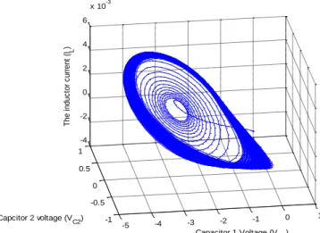
Figure 3. Chaotic behavior of the parameters above with two attractors
The values that can be taken for the parameters mentioned in
Equations 1–4 are C1 = 15.6, C2 = 1, C3 = 28, m0 = -1.143,
and m1 = = 0.714. After solving for x, y, and z with time that
can be taken from 0 to 0.05 s, by plotting the values of x, y, and z, we get observe chaotic behavior, such as in Fig. 3 and Fig. 4, in which the X–Y plane represents the voltages across the capacitors and Z represents the current across the inductor in Chua’s circuit.
-5 -4 -3 -2 -1 0 1
-1 -0.5
0 0.5 1
-4 -2 0 2 4 6
x 10-3
Capacitor 1 Voltage (VC1)
Capcitor 2 voltage (VC2)
T
h
e
i
n
d
u
c
to
r
c
u
rr
e
n
t
(IL
)
Figure 4. Chua’s circuit with one attractor
Upon changing any parameter or resistance, capacitance, or inductance values, the circuit’s behavior changes. The output of the circuit, which is implicitly deterministic, is used to encrypt and decrypt an image. Note that synchronization between the transmitter and receiver is not required for producing chaos because the Chua circuit at the receiver produces its own sequences based on the parameters and the key that should be the same as the sequences at the transmitter side.
3.
Encryption Process
The initial condition for the Chua circuit in x0, y0, and z0 is
initiated through a key Ki, which is a message or text that can
be transformed into ASCI code binary bits. These bits are concatenated to form a single number. For example, if we have a key that has 11 characters, then the ASCI code will consist of 88 bits. Then, the binary bits are shifted with a predefined number of left or right shifts cyclically three times; each time, the modulus with n, where n equals 255, is taken. The output of the modulus function is raised to a complex exponential, as in Equation 5:
) (5) where f (Ki) equals either x0, y0, or z0 and Kis is the key after it
is shifted to the right cyclically with a predetermined number of shifts, as described earlier. Note that the key can have any number of characters, provided that processor truncation errors are taken into consideration. The values of x0, y0, and
z0 are fed as an input to a Chua circuit. The output of the
the original image M × N. An XOR operation is performed between the 2D array resulting from X and the original image, which we call matrix A. However, this step does not encrypt the image. To reduce correlation in the image, we swap rows and columns horizontally and vertically. As with
X, a matrix the same size as the original image is formed from Y–Z arrays on the Y–Z plane. Each element of array Y is multiplied by all elements of array Z and a modulus operation of 255 is performed. The output of this operation is a matrix of size M × N, which is equal to the image size. The matrix can be sorted up or down, vertically or horizontally, and we can call it A. Here, it is sorted horizontally. The origin of pixels after sorting them or the number of columns are replaced instead of the sorted pixels. This matrix can be called B. The values in matrix B are used as an index for the image that resulted from the XOR operation between the original image and matrix A. To perform a vertical operation on the matrix, the columns can be transposed horizontally and the same process can be repeated. Thus, the image is shuffled and the correlation between pixels is reduced. Note that reducing the correlation between pixels is important in image encryption and in the simulation results; in simulations, we furnish the correlation coefficients horizontally, vertically and diagonally and compare them with the original image correlation factors along these directions and with other references. After getting the image pixels through the generated matrix B, a cyclic shift right is performed for every 8 bits, with a predefined number of shifts less than 8 bits. The content of pixels in matrix B is subjected to the same number of predefined rightward cyclic shifts. An XOR operation is performed between the resulting matrices. After that, each pixel is subjected to same number of shifts cyclically to the right. The resulting image is called the cipher image.
4.
Decryption Process
The decryption process is similar to the encryption process, with a few key differences that will be explained in this section. The key is sent to the receiver; the key generation process is similar to what has been mentioned above. Matrix B is formed, as it plays an important role in decryption. However, in the decryption process, the rightward shifts are reversed to the left, except for matrix B, where we need to keep the rightward shift because matrix B is similar in encryption and decryption process and an XOR operation is going to be performed that will cancel matrix B. The output pixels from this operation are subjected to same binary number of shifts to the left. The resulting image is again subjected to an XOR operation with matrix A, which resulted from array X from the Chua circuit. The pixels resulting from this operation go to the index indicated by matrix B in a newly formed matrix. The result of this process is the decrypted image. The numerous steps involved in the encryption process make it tedious to perform this decryption. The circuit parameters, the key itself, the number of shifts for the key bits, the multiplication factor for the matrices, the tractors for the solution of the chaotic problem (which is sensitive to changes in parameters) and the predefined number of shifts during encrypting the image all present a challenge for anyone attacking this cipher. Further, it is important to emphasize that the circuit is sensitive to
parameter changes, such as resistors, inductors, capacitances, the key, the number of shifts, and the method of producing the key. All these factors interact to make the scheme sensitive to changes, making it more secure and hard to break.
5.
Simulation Results
First, a key message is sent to the receiver. The key Ki used
for simulation is ($#@!*&()_+54321Hello.
-20 -10
0 10
20
-100 -50 0 50 100 -0.4 -0.2 0 0.2 0.4
Capacitor 1 Voltage (VC1) Capcitor 2 voltage (VC2)
Th
e
in
du
ct
or
c
ur
re
nt
(
IL
)
Figure 5. Chua’s circuit solution with initial conditions x0 =
0.941, y0 = 0.577, and z0 = 0.3341
After processing the key as described in Section 3, the initial values of x0, y0, and z0 are 0.941, 0.577, and 0.3341,
respectively. The resulting solution with the initial conditions given above is shown in Fig. 5.
Matrixes A and B are formed: encrypted images are shown for two examples in Fig. 6 (a) and Fig. 6(c). These images are the standard cameraman and board images.
(a) (b)
The Encrypted Image The Decrypted image
(c) (d)
Figure 6. Using the key ($#@!*&()_+54321Hello with predetermined shifts (6 bits for the key and 2 bits for the image pixels). (a) and (c) show the encrypted images (b) and
(d) show the decrypted cameraman and board images. The predetermined shifts for encryption and decryption are 6 bits for the key and 2 bits for the image pixels. At the receiver, with the key given above, the output arrays are
formed and processed as explained earlier. The decrypted images are shown in Fig. 6(b) and Fig. 6(d).
5.1 Parameter Mismatches
To test the encryption performance of this scheme, we show a simple test where the rightward binary shift during encryption and decryption do not match. As mentioned previously, there are plenty of parameters that can be chosen to test the encryption and decryption process. One of these parameters is the predetermined number of binary shifts to the right when processing matrix B and the image that came from the XOR operation between matrix A and the original image. When there is a mismatch between the shifts—here, 1 bit in the encryption process and 2 bits in the decryption process—the process fails to decrypt the image. An example is shown in Fig. 7 below.
The Encrypted Image The Decrypted image
(a) (b)
Figure 7. Binary shift mismatch between encryption and decryption. (a) The image was encrypted with a shift of 1 bit
and (b) decrypted with a shift of 2 bits.
5.2 Statistical Analysis
The robustness of the proposed scheme was tested using histogram analysis, correlation coefficient analysis, and differential attack analysis.
5.2.1 Histogram Analysis
The histogram of an image shows the distribution of its pixel content. Comparing the histograms of the encrypted and original images can ensure that the ciphered image has no clue of the original pixel distribution and any attempt to crack the cipher is going fail. Figure 8 shows histograms for the original and ciphered board image.
0 50 100 150 200 250 300
0 50 100 150 200
The original image
0 50 100 150 200 250 300
0 20 40 60 80
The encrypted image
Figure 8. The histograms of both the original and encrypted images, respectively
By comparing both, we deduce that the correlation between the ciphered image pixels is almost null, as is required to hide any clue of the statistical distribution of the original image.
5.2.2 Pixel correlation
The correlation factor is also important when studying a cryptosystem—the original image pixels are highly correlated, whereas those of the encrypted image should be very low. Calculation of the correlation coefficient for both the original and encrypted images is performed between adjacent pixels. Suppose we have matrixes C and D of the same size; then, the correlation coefficient, represented as r, can be calculated using Equation 6.
(6)
where and are the means of matrixes C and D, respectively. We used Equation 6 to calculate this correlation coefficient horizontally, vertically, and diagonally. The simulation results show that there is a strong correlation for the original image horizontally, vertically, and diagonally; for the encrypted image, the correlation coefficients are far lower. We tested a variety of standard images; the results of this test are shown in Table 1.
Table 1. Comparing correlation coefficients for encrypted and decrypted grayscale images horizontally, vertically, and diagonally
Image name
Correlation coefficients
Type Horizontal Vertical Diagonal
Cameraman Original 0.9701 0.9519 0.9273
Encrypted 0.0842 0.024 0.0471
Pout Original 0.9821 0.9829 0.9766
Encrypted 0.1419 0.0505 -0.0955
Trees Original 0.9704 0.9644 0.9098
Encrypted 0.1589 0.0328 -0.049
Circuit Board Original 0.9636 0.8875 0.827
Encrypted 0.0191 0.0127 0.0739
Forest Original 0.9257 0.9009 0.8015
Encrypted 0.2817 0.0246 0.1054
Greens Original 0.8782 0.8034 0.7668
Encrypted 0.028 0.0157 0.0285
Table 1 clearly shows that the pixels of all the original images are highly correlated in all directions, ranging from a maximum of 98.12% along the horizontal direction in the pout image to a minimum of 76.68% along the diagonal direction in the greens image. However; for the encrypted images, the maximum correlation coefficient registered is along the horizontal direction in forest image, with a value of 28.17%, which is low compared with the original image for the same direction.
Table 2. Comparison of the proposed scheme with references 28, 29, and 30
Image name
Metrics Proposed
algorithm
Ref [28] Ref [29] Ref[30]
Encrypted
cameraman 256 x 256
Horizontal 0.0842
-0.000944
0.0063 -0.0251
Vertical 0.024
-0.009439
-0.0099 0.0123
Diagonal 0.0471 0.000474 -0.0076 -0.0236
Encrypted Lena 256 x 256
Horizontal 0.0976 0.0007 0.0069 0.0044
Vertical 0.0246 0.02045 0.0047 0.0151
Diagonal -0.1380 -0.0025 0.0056 0.0012
Encrypted
baboon 256 x 256
Horizontal 0.0401 -0.00032 -0.0063 -0.0058
Vertical 0.0230 0.000334 0.007 0.0131
Diagonal 0.0776
-0.001161
50 100 150 200 70
80 90 100 110 120 130 140 150 160 170
pixel value on location (x,y)
pi
xe
l v
al
ue
o
n
lo
ca
tio
n
(x
,y
+
1)
Scattered diagram of the original image
0 100 200 300
0 50 100 150 200 250 300
pixel value on location (x,y)
pi
xe
l v
al
ue
o
n
lo
ca
tio
n
(x
,y
+
1)
Scattered diagram of the encrypted image
Figure 9. Scatter plots for the original and encrypted images Moreover, the minimum correlation coefficient, registered along diagonal in the pout image, had a value of −9.55%, compared to a high value with the original image along the same direction, 97.66%. A comparison of the proposed scheme with other references [28–30] of the correlation coefficients along the horizontal, vertical, and diagonal directions of the cameraman, Lena, and baboon images is shown in Table 2. Additionally, scatter plots for the original and encrypted cameraman images are shown in Fig. 9, which illustrates that the pixels are highly correlated in the original image and have very low correlation in the encrypted image.
5.2.3 Differential attack analysis
One method that can be used to check a cipher’s resistance to attacks is a differential attack. Biham and Shamir [26] based the foundation for these attacks on block ciphers. A cipher’s resistance to differential attacks is measured through two factors: the first is the number of pixels changed rate (NPCR) and the second the unified average changing intensity (UACI). If we represent two images of size M × N—either
plain or ciphered—as C1 and C2 and we would like to define
a bipolar array represented as D that has a similar matrix size as the plain or ciphered image, then D has either a value of 0 or 1. To determine the value of D, we apply a condition: if
C1(i, j) = C2(i, j), then D = 0; otherwise, D = 1. As NPCR’s
name implies, we count the number of pixels that have changed in both images and divided by M × N, as shown in Equation 7.
(7) UACI can be represented with the following equation:
(8) where, c1(i, j) and c2(i, j) are the first and second ciphered or
plain images. The mean absolute error (MAE) is represented by Equation 9.
(9) Calculations of the NPCR, USCI, and MAE were calculated for six images: cameraman, pout, trees, circuit board, forest, and greens. The results are listed in Table 3.
Table 3. NPCR, UACI, and MAE calculations for six example images.
Image NPCR UACI MAE
cameraman 99.5063 30.7447 84.8003
Pout 99.6509 26.5314 85.3870
Trees 99.626 37.777 84.426
Circuit Board 99.497 31.514 84.819
Forest 99.559 42.562 84.235
Greens 99.977 35.810 91.32
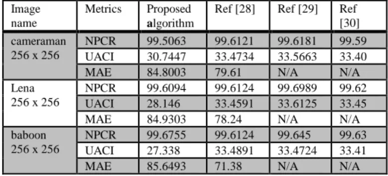
The proposed scheme is also compared with references 28– 30 in terms of NPCR, UACI, and MAE applied to the cameraman, Lena, and baboon images. The comparisons are given in Table 4. Data that were not available in the reference are listed as N/A.
Table 4. NPCR, UACI, and MAE comparisons for cameraman, Lena, and baboon
Image name
Metrics Proposed
algorithm
Ref [28] Ref [29] Ref [30] cameraman
256 x 256
NPCR 99.5063 99.6121 99.6181 99.59
UACI 30.7447 33.4734 33.5663 33.40
MAE 84.8003 79.61 N/A N/A
Lena 256 x 256
NPCR 99.6094 99.6124 99.6989 99.62
UACI 28.146 33.4591 33.6125 33.45
MAE 84.9303 78.24 N/A N/A
baboon 256 x 256
NPCR 99.6755 99.6124 99.645 99.63
UACI 27.338 33.4891 33.4724 33.41
MAE 85.6493 71.38 N/A N/A
5.2.4Information entropy
The information content of a signal is called its entropy. Entropy describes the information redundancy associated with feature randomness. For example, an entropy of 6.53 bits per pixel for an image describes the statistical average number of bits required to represent a pixel in the image. Entropy can be represented mathematically as follows [26]:
where is the occurrence probability of a pixel in an image, N is the length of a pixel in binary numbers (usually, a grayscale image has the value N = 8), and H(s) is the entropy described in bits per pixel or symbol. One property any cryptosystem should possess is the ability to resist an entropy attack; the ideal entropy value of the encrypted images should be 8 bits per pixel [25].
Table 5. The entropy of some plain grayscale images and their corresponding encrypted images
S/N Grayscale image
(256 x 256) pixels
Entropy of original image (bits/pixel)
Entropy of encrypted image (bits/pixel)
1 Cameraman 7.0508 7.030
2 Pout 6.1894 6.172
3 trees 6.5300 6.512
4 Circuit board 7.6260 7.618
5 Forest 5.3360 5.328
6 Greens 7.3830 7.378
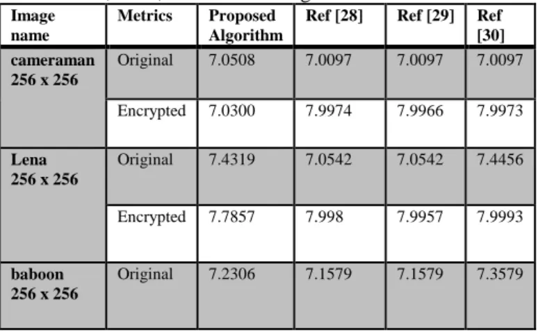
compared with those of references 28–30; the results are shown in Table 6.
Table 6. Entropy comparisons with references 28–30 for the cameraman, Lena, and baboon images
Image name
Metrics Proposed
Algorithm
Ref [28] Ref [29] Ref
[30] cameraman
256 x 256
Original 7.0508 7.0097 7.0097 7.0097
Encrypted 7.0300 7.9974 7.9966 7.9973
Lena 256 x 256
Original 7.4319 7.0542 7.0542 7.4456
Encrypted 7.7857 7.998 7.9957 7.9993
baboon 256 x 256
Original 7.2306 7.1579 7.1579 7.3579
5.2.5Peak Signal-to-Noise Ratio
The peak signal-to-noise ratio (PSNR) is defined as the ratio between the maximum value of the signal to the root mean squared error expressed in decibels (dB), as given in the following equation [27]:
(11) where is the maximum value of the original image f(x, y) and MSE is the mean squared error, which can be expressed in the following equation [27]:
(12)
where f(i, j) represents the original image and g(i, j)
represents the decrypted or recovered image. The PSNR for different grayscale images was calculated for the encrypted and decrypted cameraman, pout, trees, circuit board, forest, and greens images and the results are shown in Table 7. The
MSE between the components of the original images and the components of the encrypted or decrypted images is calculated based on Equations 12 and 11. Note that the decrypted greens image had the minimum calculated PSNR among all images, 30.262 dB, whereas the decrypted cameraman image had the maximum, 43.018 dB. The PSNRs of the encrypted grayscale images are shown in the same table: the maximum calculated PSNR, for the encrypted pout image, is 9.0097 dB and the minimum calculated PSNR, for the grayscale trees image, is 1.0489 dB.
Comparing the PSNR of the encrypted and decrypted images demonstrates that, due to the low correlation between pixels after applying the encryption scheme, the PSNR values of the encrypted images are very small.
Table 7. PSNR comparison of some encrypted and decrypted grayscale images
Image name (grayscale)
PSNR(dB) Encrypted image
PSNR(dB) Decrypted image
Cameraman 8.4214 43.018
Pout 9.0097 41.942
Trees 1.0489 34.725
Circuit board 8.2936 38.84
Forest 5.8809 37.825
Greens 7.175 33.626
6.
Conclusions
Chaos theory has attracted considerable attention over the past decade. Due to the deterministic nature of chaos, it can be used for encryption. One of the circuits that produces chaos is Chua’s circuit. In this paper, Chua’s circuit output, which is biased through initial conditions extracted using the ASCI code of the characters comprising the key with a predefined number of shifts and modulus od 255, is used to encrypt an image. From the output of the circuit, two matrices are produced; the matrix in Y–Z plane is used to shuffle the pixels of the image after they are XORed with the first matrix. However; the pixels in the plain image are highly correlated. This correlation is reduced using the second matrix, which resulted from the Y–Z arrays, which is sorted up or down; its pixels are used as indices for the image resulting from the XOR operation with cyclic right shifts, producing the ciphered image. Simulation results show that the pixels are scattered. At the receiver side, the ciphered image is decrypted; changing one factor in the decryption causes the process to fail, showing the sensitivity of the scheme. Further, there are plenty of factors, such as the circuit parameters (resistors, capacitors, voltage amplitude, voltage frequency, and inductors), the number of shifts for the key and during encryption, the length of the key, and the multiplication factor n that, together, make this cipher very hard to attack.
References
[1] A. A. Khare, P. B. Shakla, S. C. Silakari, “Secure and fast chaos based encryption system using digital logic circuit,” International Journal of Communication Networks and Information Security, Vol. 6, No. 6, pp. 25-33, 2014. [2] R. Ye, W. Guo, “An image encryption scheme based on
chaotic systems with changeable parameters,” International Journal of Communication Networks and Information Security, Vol. 6, No. 4, pp. 37-45, 2014.
[3] W. Stallings, “Cryptography and Network Security Principles and Practices,” Pearson Education Limited, Harlow, 2010. [4] W. Zhang, H. Yu, Y. L. Zhao, Z. L. Zhu, “Image encryption
based on three dimensional bit matrix permutation,” Signal Processing, Vol. 118, pp. 36-50, 2016.
[5] J. Ahmad, M. A. Khan, S. O. Hwang, J. S. Khan, “A compression sensing and noise-tolerant image encryption scheme based on chaotic maps and orthogonal matrices,” Neural Computing and Applications, Vol. 28, pp. 953-967, 2017.
[6] S. H. Strogatz,”Nonlinear Dynamics and Chaos,” 2nd edition, CRC Press, Boca Raton, 2018.
[7] G. C. Layek, “An introduction to dynamical systems and Chaos,” Springer India, New Delhi, 2015.
[8] X. Zhang, X. Fan, J. Wang, Z. Zhao, “A chaos-based image encryption scheme using 2D rectangular transform and dependent substitution,” Multimedia Tools and Applications, Vol. 75, No. 4, pp. 1745-1763, 2014.
[9] Z. H. Guan, F. Huang, W. Guan, “Chaos-based image encryption algorithm,” Physics Letters A, Vol. 346, No. 1-3, pp. 153-157, 2005.
[10] W. Yao, X. Zhang, Z. Zheng, W. Qiu, “A colour image encryption algorithm using 4-pixel Feistel structure and multiple chaotic systems,” Nonlinear Dynamics, Vol. 81, No. 1-2, pp. 151-168, 2015.
compressive sensing," Optics and Laser Technology, Vol. 82, pp. 121−133, 2016.
[12] L. Xu, X. Gou, Z. Li, J. Li, “A novel chaotic image encryption algorithm using block scrambling and dynamic index based diffusion," Optics and Lasers in Engineering, Vol. 79, pp. 41-52, Apr. 2017.
[13] X. Wang, J. Gan, “A chaotic encryption method,” Chinese Journal of Computers, Vol. 25, No. 4, pp. 351-356, 2002. [14] M. K. Mandal, M. Kar, S. K. Singh, V. K. Barnwal,
“Symmetric key image encryption using chaotic Rossler system,” Security and Communication Networks, Vol. 7, pp. 2145-2152, 2013.
[15] A. Elshamy, A. Rashed, A. Mohamed, O. Faragallah, Y. Mu, S. Alshebeili, F. Abd El-samie, “Optical image encryption based on chaotic baker map and double random phase encoding,” Journal of Lightwave Technology, Vol. 31, No. 15, pp. 2533-2539, 2013.
[16] G. Chaitanya, B. Kerthi, A. Saleem, A. Trindah Rao, K.T. Kumar, “An image encryption and decryption using chaos algorithm,” IOSR Journal of Electronics and Communication Engineering, Vol. 10, No. 2, pp. 103-108, 2015.
[17] A. S. Andreatos, A. P. Leros “Secure image encryption based on a Chua chaotic noise generator,” Journal of Engineering Science and Techology Reviews, Vol. 6, No. 4, pp. 90-103, 2013.
[18] M. Z. De la Hoz, L. Acho, Y. Vidal, “A modified Chua chaotic oscillator and its application to secure communications,” Applied Mathematics and Computation, Vol. 247, pp. 712-722, 2014.
[19] K. Loukhaoukha, J. Y. Chouinard, A. Berdai, “A secure image encryption algorithm based on Rubik's cube principle,” Journal of Electrical and Computer Engineering, Article ID 173931, 2012.
[20] N. Taneja, I. Gupta, “Chaos based cryptosystem for still visual data,” Multimedia Tools and Applications, Vol. 61, No. 2, pp. 281-298, 2012.
[21] S. Rakesh, A. A. Kaller, B. C. Shadakshari, “Image encryption using block based uniform scrambling and chaotic logistic mapping,” International Journal on Cryptography and Information Security, Vol. 2, No. 1, pp. 49-57, 2012. [22] A. Jolfael, A. Mirghadri, “An image encryption approach
using chaos and stream cipher,” Journal of Theoretical and Applied Information Technology, Vol. 19, No. 2, pp. 117-125, 2010.
[23] C. Dong, “Color image encryption using one-time keys and coupled chaotic systems,” Signal Processing: Image Communication, Vol. 29, No. 5, pp. 628-640, 2014.
[24] X. Wang, L. Teng, X. Qin, “A novel colour image encryption algorithm based on chaos,” Signal Processing, Vol. 92, No/ 4, pp. 1101-1108, 2012.
[25] N. Zhou, A. Zhang, F. Zheng, L. Gong, “Novel image compression-encryption hybrid algorithm based on key-controlled measurement matrix in compressive sensing,” Optics & Laser Technology, Vol. 62, pp. 152-160, 2014. [26] E. Biham, A. Shamir, “Differential Cryptanalysis of the Data
Encryption Standard,” Springer-Verlag, New York, 1993. [27] X. Huang, G. Ye, H. Chai, O. Xie, “Compression and
encryption for remote sensing image using chaotic system,” Security and Communication Networks, Vol. 8, No. 18, pp. 3659-3666, 2015.
[28] B. Norouzi, S. M. Seyedzadeh, S. Mirzakuchaki, M. R. Mosavi, “A novel image encryption based on row-column, masking and main diffusion processes with hyper chaos,” Multimedia Tools and Applications, Vol. 74, No. 3, pp. 781-811, 2015.
[29] T. Zhang, S. Li, R. Ge, M. Yuan, Y. Ma, “A novel 1D hybrid chaotic map-based image compression and encryption using compressed sensing and Fibonacci–Lucas transform,”.
Mathematical Problems in Engineering, Article ID 7683687, 2016.