Study of Surface Roughness on Induction Hardened Steel using CBN Cutting Tool
S. Thamizhmanii¹, K. Kamarudin, Badrul, A. Saparudin, S. Hassan ¹ Faculty of Mechanical and Manufacturing Engineering
Universiti Tun Hussein Onn Malaysia 86400, Parit Raja, Batu Pahat, Johor, Malaysia.
E mail: [email protected]
Abstract:
The hard turning is stand for substitute for grinding process and avoids coolant. Many researches had conducted study and found that it is possible to super finish hard material and possible to obtain surface roughness of 2 – 8 µm by using advanced cutting tool materials like ceramic, CBN and PCBN. The coated ceramic tool was used to machine SCM 440 induction hardened material. The hardness of the material was between 60 to 65 HRC. The turning process was carried under dry cutting condition. There were improvements in surface roughness at high cutting speed, low feed and low depth of cut. There were variations in surface roughness at the point where the hardness is high. Nose wear were dominant in the tool during turning than any other wear.
1. INTRODUCTION
Hard turning of machine parts is production process for future and it is effective means of increasing productive. Hard turning stands for substitution for the grinding process and enables the avoidance of coolant [1]. The elimination of grinding will be of help to environment. It is shown that it is feasible to use hard turning under selected conditions to super finish surfaces, hardened to 65 HRC by induction hardening process, to a surface finish of 2 to 8 µm [1]. Machining of hardened steels using advanced cutting tool materials such as CBN, has certain advantages over the traditional cutting –hardening – grinding practice in terms of improved fatigue strength of the machined parts, increased productivity and reduce energy consumption [2]. The hard turning also gives significant in cost saving and productivity [3]. The development of new cutting tools offer increased hardness, toughness, and strength to cut high hardness materials. These materials include especially coated micro grain carbides, ceramics, CBN and PCBN inserts. In hard turning the property of cutting tool materials must be improved to
reduce the flank wear to make it more suitable for precision applications [4].
2. EXPERIMENTAL SET-UP
2.1. Work piece
The work piece was cut to 300 mm in length from 1000 mm long bar having diameter of 50 mm. The work piece was skin turned to remove various scoring marks caused by transport. The work piece provided with centres on both sides to accommodate in dead centre for turning and also for induction hardening. The face of the work piece was divide into four segments and stamped as 1, 2,3 and 4. The chemical composition and mechanical properties are shown in the Table 1 and 2. This was done to measure the surface roughness at four points equally and arrive at an average value. The hardness before induction hardening was 25 Hv. The hardness was maintained between 65 to 70 HRc to a case depth of 3 to 3.5 mm. The higher the case depth, more time to wear. There were four pieces for this experiment and work piece was taken arbitrarily. After the induction hardening, the work pieces were thoroughly for checked for the presence of micro cracks. The experiments were conducted maintaining one constant parameter for each trail. The Harrison lathe M400 is having provision to increase the spindle speed and feed by increment. The surface roughness was measured immediately after each trial using Mitutoyo surf test SJ400 equipments. The cutting conditions are shown in the Table 3. The following units are used i) surface roughness in µm, ii) the tool wear in microns, iii) cutting speed in m/min, iv) feed in mm/rev. and v) depth of cut (doc) in mm.
2.2. Induction hardening
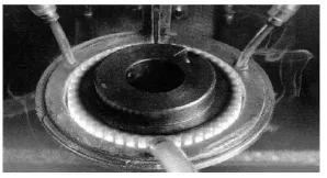
The purpose of induction hardening is to obtain hard wear resistant whilst the core remains soft. The process of induction hardening differs from other heat process. Less time is required for where as other process takes longer time. This process can help to do at selective places where as other process it is not possible. In this process high frequency current ranging from 1000 to 10, 000 cycles per second was passed through a copper inductor coil which acts as primary coil of the transformer. Heating by high frequency is accomplished by the thermal effect of the current induced in the
work piece being heated. The work piece is placed in an inductor coil which comprises one or several turns of copper tube or bus bar. The alternating magnetic lines pass through the surface of the work piece being heated in an inductor coil and induce in the surface an alternating current of the same frequency but reversed in direction. This alternating current produces heating effect of the surface and temperature produced in the order of 750 to 800º C.
The heating area is quenched immediately by sprays of water delivered through numerous small holes in the inductor block [9]. The medium and high carbon content materials are used for induction hardening. A typical process is shown in the Figure 1. Induction surface hardening usually introduce compressive residual stresses in the substrate surface. A disadvantage of induction surface hardening is the necessity of an own induction coil for each tool.
Table1: Chemical composition of SCM 440.
C % Mn % Cr % Mo % Ni % 0.38/
0.41
0.80/ 1.05
0.90/ 1.20
0.08/ 0.15
0.00
Table2. Mechanical properties of SCM 440.
Yield stress Tensile
stress Hardness
557 MPa 664 MPa 65 to 70
HRC
Table 3: Operating Parameters
Work piece size in mm Dia. 50 x Length 300 Cutting speed m /min. 63, 125, 188 Feed mm /rev. 0.20, 0.30,0.40 Depth of cut mm 0.05, 0.10, 0.20, 0.30 Lubrication No
Table 4: Properties of cutting tool
Hardness HV 2800
Fracture toughness 5.0 MPa Flexural Strength 90 – 110 (MPa)
Figure 1: Induction Hardening Process.
2.3. Cutting Tool
The cutting tool used was CBN tool manufactured by KYOCERA and the grade is KBN 10B CNGA 120402SE. The cutting tool CBN KBN 10 B is a synthetically produced and stable under high temperature conditions. Table 4 shows the features of KBN 10B cutting tool. The manufacturer claims that this cutting tool is suitable for high speed machining of heat treated steel due to less reactivity to iron.
3. RESULT AND DISCUSSION
3.1. Effect of Cutting Speed and Feed on Surface Roughness.
The experiment was conducted using cutting parameters as shown in the table 3.The results obtained at constant depth of cut by varying cutting speeds and feeds are shown in the Figures 2, 3, 4 and 5. The cutting speed of 188 m / min. has produced at most equal surface roughness Ra values of 0.39 and 0.43 µm having 0.20 and 0.40 feed respectively. The higher cutting speeds in all the experiments have produced lowest roughness value. The cutting tool nose radius was 0.40 mm and all the feeds used are all less than nose radius size and hence lower values of surface roughness. Figures 6, 7, 8 and 9 are against feed and surface roughness values.
3.2. Cutting Tool Wear
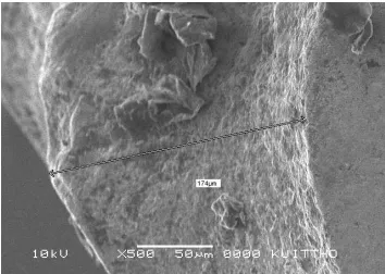
The wear of ceramic and CBN tools is decreased with an increase of hardness, but at about HRC 50, the wear started to increase [10]. Tool life directly affects the non-capital machining cost, particularly on the effects of CBN tool wear, and binder composition. It was found that the nose wear to 174 µm as shown in the Figures 10 and 11. This wear was negligible. There was trace of flank wear due to lowest depth of cut used. There were small
particles from work piece sticking on to the flank side of the tool to a size of 34.8 x 17.2 µm as shown in the Figure 11. This is due to the temperature between tool interface and work piece.
Figure 2 Cutting Speed Vs Surface Roughness at doc of 0.05 mm
Figure 3 Cutting Speed Vs Surface Roughness at doc of 0.10 mm
Figure 4 Cutting Speed Vs Surface Roughness at doc of 0.20 mm
Figure 5 Cutting Speed Vs Surface
0.55 0.71 0.99 0.57 1.03 1.86 0.68 1.65 1.74 0 0.5 1 1.5 2
63 125 188
Cutting Spe ed m / m in.
S u rf a c e R o u g h n e s s R a
Feed 0.20 Feed 0.30 Feed 0.40
0.82 0.65 0.88
0.48 1.85 2.5 0.4 1.6 1.8 0 0.5 1 1.5 2 2.5 3
63 125 188
Cutting Speed m / m in.
S u rf a c e R o u g h n e s s R a
Feed 0.20 Feed 0.30 Feed 0.40
2.29 2.5 0.39 2.68 3.5 0.78 4.01 4.25 0.43 0 2 4 6
63 125 188
Cutting Speed m / min
S u rf a c e R o u g h n e s s R a
Feed - 0.20 Feed - 0.30 Feed -0.40
1.62 1.72 1.02 3.5 3.02 0.99 4.4 4.75 0.54 0 1 2 3 4 5
63 125 188
Cutting Spe ed m / m in.
S u rf a c e R o u g h n e s s R a
Roughness at doc of 0.30 mm
Figure 6 Feed Vs Surface Roughness at doc of 0.05 mm.
Figure 7 Feed Vs Surface Roughness at doc of 0.10 mm.
Figure 8 Feed Vs Surface Roughness at doc of 0.20 mm.
[image:4.612.329.506.71.197.2]Figure 9. Feed Vs Surface Roughness at doc 0.30 mm.
[image:4.612.327.504.258.386.2]Figure 10 SEM view on nose wear of 174 µm
Figure 11 SEM View on particles sticking on Flank side, size 34.8 x 17.2 µm.
4. CONCLUSIONS
The objective of the experiments was to obtain lowest surface roughness Ra value. The following are the conclusions:
a. The lowest value of Ra value was obtained at lowest feed rate, lowest depth of cut and highest cutting speed. From this experiment, 188 m / min cutting speed, 0.20 and 0.30 feed rate with 0.05 mm depth of cut was recommended.
b. The cutting tool show the wear on nose of radius to a size 174 µm and small particles from the work piece was sticking on flank side of the tool.
c. The Ra value was also high at few cutting speeds which may be due to highest hardness at that particular area. The hardness at that area of machining was unable to check due to experimental constraints.
0.55 0.57 0.68
0.71
1.03
1.65
0.99
1.86 1.74
0 0.5 1 1.5 2
0.2 0.3 0.4
Fe e d m m / rev.
S
u
rf
a
c
e
R
o
u
g
h
n
e
s
s
R
a
C.S.63 C.S.125 C.S.188
1.62
3.5
4.4
1.72
3.02
4.75
1.02 0.9 0.75
0 1 2 3 4 5
0.2 0.3 0.4
Fee d m m / rev.
S
u
rf
a
c
e
R
o
u
g
h
n
e
s
s
R
a
C.S.63 C.S.125 C.S.188
0.82 0.65 0.88
0.48
1.85
2.5
0.4
1.6 1.8
0 0.5 1 1.5 2 2.5 3
63 125 188
C u t t i n g S p e e d m / m i n . Feed 0.20 Feed 0.30 Feed 0.40
0.82
0.48 0.4
0.65
1.85
1.6
0.88
2.5
1.8
0 0.5 1 1.5 2 2.5 3
0.2 0.3 0.4
Feed m m / rev.
S
u
rf
a
c
e
R
o
u
g
h
n
e
s
s
R
a
REFERENCES
[1] X.l.Liu, D.H.Wen, Z.J.Li, L.Xiao, F.G.Yan, Experimental study on hard turning hardened GCr15 steel with PCBN tool., Journal of Materials Processing Technology 129 (2002) 217-221.
[2] Wuyi Chen, Cutting forces and surface finish when machining medium hardness steel using CBN tools, International Journal of Machine tools and Manufacture 40 (2000) 455-466.
[3] S.Y.Luo, Y.S.Liao, Y.Y.Tsai, Wear characteristics in turning high hardness alloy steel by CBN tools, Journal of Materials Processing Technology, 88 (1999), 114-121.
[4] G.Poulachon, A.Moisan, I.S.Jawahir, Tool wear mechanisms in hard turning with PCBN nitride tools, wear 250 (2001) 576-586.
[5] N. Narutaki and Y.Yamane, Tool wear and cutting temperature of CBN tools in machining of hardened steels, Annals of CIRP, 28 (i),pp.23-28, 1979.
[6] J.M. Zhou, H.Walter, M.Andersson, J.E. Stahl, Effect of chamfer angle on wear of PCBN cutting tool, International Journal of Machine tools and Manufacture 43 (2003) 301-305.
[7] W.P.Koster, M.Filed, L.J.Fritz, L.R. Gatto, J.K.Kahlets, Technical report, AFML,-TR-70-11, Merchant Research Associates, Inc.1970.
[8] X.Luo, K.cheng, R.Holt, X.Liu, Modeling flank wear of carbide tool insert in metal cutting, Wear 259 (2005) 1235- 1240. [9] R.K.Jain, Prodduction Technology, 16 the
edition, Khanna publishers, pp 111, 2003. [10] S.Y.Luo, Y.S.Liao, Y.Y.Tsai, Wear
characteristics in turning high hardness alloy steel by ceramic and CBN tools, Journal of Material Processing Technology 88(1999) 114-121.
[11] O.Kessler, Th.Herding, F.Hoffmann, P.Mayr, Microstructure and wear resistance of CVD TiN –coated and induction surface hardened steels, Surface and coatings Technology 182 (2004) 184-191.
[12] Y. Kevin Chou, Chris J. Evans, Tools wear mechanism in continuous cutting of hardened tool steels, Wear 212 (1997) 59-65.
Acknowledgement