© 2018, IRJET | Impact Factor value: 6.171 | ISO 9001:2008 Certified Journal | Page 815
Comparative study of effect of different positions of shear wall on
transfer girder for wind, conventional and stage analysis.
Vikas V. Mehetre
1, V.T.More
21 PG Student Department of Civil Engineering, MGM JNEC Aurangabad, Maharashtra, India
2 Assistant Professor, Department of Civil Engineering, MGM JNEC Aurangabad, Maharashtra ,India
---***---Abstract
-In recent year, many multi-storey and commercialbuilding are constructed with Floating column and transfer girder due to special architectural requirement. Floating column and transfer girder also provide for creating space for parking, assembly hall purpose. The floating column is concentrated load on the transfer girder which supports it. These type of structure are unsafe in region where more chances of earthquake occur. For high rise structure with floating column and transfer girder seismic analysis, wind analysis and sequential analysis is necessary to check behavior of structure. During earthquake storey shear transfer to ground at shortest path but due to floating column and transfer girder there will be discontinuity in load transfer path. These types of structure is danger in earthquake. The present study involve the analysis like conventional analysis and construction stage analysis with earthquake for zone IV (Delhi) and wind analysis for wind speed 47m/s (Delhi. Which is done on 10, 15,20,25,30 storey RCC building with floating columns at four places of the frame and each storey case also analyze for different shear wall positions such as shear wall at corner, core ,without and periphery by using ETABS V-2015 software. Finally effect of shear wall for each model is observed in the form of bending moments, displacement.
Key Words: Transfer girder, shear wall, wind analysis,
construction stage analysis, floating column.
1. INTRODUCTION
Today many residential and commercial building adopted floating column to provide open space for parking, assembly hall purposes and also provide for good aesthetic view.
During earthquake storey shear need to be transferred down to the ground by the shortest path; any discontinuity in the structural member results in change in the load path. Building having vertical setback cause a sudden variation in earthquake forces at the level of discontinuity. The discontinuities in the load path are formed in the buildings with floating columns at an intermediate storey or ground storey and do not continue up to foundation. Shear wall are provide for high rise building to resist lateral loads. These walls generally start from foundation level and they are continuous throughout the floor of the building. They can have minimum thickness of 150-600mm.Shear wall provide lateral stiffness to structure to resist earthquake and wind loading. For high rise structure contain floating column and transfer girder, we also provide shear wall to reduce lateral
movement of structure. Shear wall also reduce the structural responses of transfer girder at different positions.
1.1 Wind Analysis
Wind analysis is the behavior of building i.e. laterally for wind or air. Wind analysis is essential for high rise structure because we are going to 30 m above from plinth level wind pressure is very high. For this reason wind analysis is done for most of the building in the software.
1.2 Construction Stage Analysis
Generally, the structures are analyzed and designed using one step using conventional analysis or seismic analysis on the assumption that the structure will be fully loaded at once. But in actual practice, the structure is constructed storey by storey hence dead load is applied storey-wise and the finishing loads are also imposed as the structure is constructed in stage wise. Conventional analysis or the seismic analysis is carried out in a one step whereas the construction stage analysis is carried out considering the actual sequence of construction of the building. To get the sequential effects, each story should be analyzed with its next stories by assigning the vertical loads as stage wise using ETABS. The effects of the sequential or stage-wise construction can be seen and understood once the construction sequential analysis is completed. This type of analysis is complex in nature but due to advancement of structural software, this is done quickly. This type of analysis gives actual behavior of structure, and we are also take this analysis result for design of structure in more precisely .
2. LITERATURE REVIEW
Tabassum G Shrihatti and Vanakudre S.B (2015) [1] ,investigate the effects of conventional analysis and the construction stage analysis RC and steel buildings. Three-dimensional modeling of RCC and steel 30 storey building situated in zone IV and hard soil type is consider and the analysis results are obtained. In both the buildings the frames are consider as rigid frame. Finally, the results like shear force, bending moment and displacements were compared with both the conventional model and construction sequence model of RCC and building respectively using the ETABS-2013 software.
© 2018, IRJET | Impact Factor value: 6.171 | ISO 9001:2008 Certified Journal | Page 816 are analyze for construction sequence and conventional
method for zone-II and compared there bending moments, shear forces and displacements for geometric nonlinearity material nonlinearity.
Yousuf Dinar, Munshi Md. Rasel, Muhammad Junaid Absar Chaudhary, Md. Abu Ashraf (2014)] [3], reviews about the rigid frame structures of both concrete and steel model of different configurations that have been taken for sequential analysis. The analysis result helps us to understand how the structure respond against loads of construction sequential analysis and linear static analysis. The sequential analysis results were compared with conventional analysis results. The effect of sequential construction and its effect on the overall design of the building has been evaluated using finite element modeling. In this work, multi-storey buildings of 5, 10, 15, 20, 25 and 30 storey with a floating column in exterior position is considered. The parameters like column axial load and beam maximum moment is compared with both the analysis using ETABS 9.7.2 software.
Meghna B.S and T.H Sadashiva Murthy (2016) [4], here a RC building structure of G+ 5 storey with floating column in exterior position and RC transfer girder is replaced by composite transfer girder and the analysis of the model is carried out with the help of ETABS software. The analysis involved here are conventional analysis and construction sequence analysis and the parameter such as beam moments and deflection of both the buildings are compared.
Vignesh Kini K., Rajeeva S.V.(2017) [5], investigate about the behavior of composite and RCC girder and there comparison for response spectrum analysis and construction sequence analysis for zone-II in the form of bending moments, displacement and shear force of transfer girder,with the help of CSI ETABS 2016.
R.Pranay,I.Yamini Sreevalli,Er.Thota.Suneel Kumar (2014) [6], It take G+21 storey structure and analyze for conventional method and construction sequence method. Compare bending moment, displacement and shear force of transfer girder which is provide at 1st floor at two location by construction stage analysis and conventional analysis.
Sri Harsha B and Vikranth J (2014) [7], investigate about the factor which is affecting limit state of serviceability of structure that is sequential construction and strength of concrete. Here two cases, conventional analysis for building subjected to whole loading construction stage analysis for the building subjected to stage loading are considered and deformation in both the cases are compared with two analysis.
Meghana B.S and T.H. Sadashiva Murthy (2016) [8], reviews on RC and steel-concrete composite building with floating column in different places in plan. Different buildings such as G+3, G+10 and G+15 storey in earthquake zone II and V were analyzed using conventional analysis using ETABS software. Structural responses such as storey shear, storey drift and
storey displacement were compared with the results of normal RC building.
2.1 Need for Present Study
The present literature survey investigate that works have been done on the behavior of RC, steel and composite girder with different storey and different loads i.e. Floating Column and transfer girder are analyzed for response spectrum method, construction sequence method, wind method and conventional method. In high rise structure shear wall are provided to resist lateral loads but we don’t know the effect of different positions of shear wall on transfer girder. So, it is required to study the behavior of structure with floating column ,transfer girder and shear wall by analyzing structure using construction sequence analysis, wind analysis and conventional analysis.
3. OBJECTIVES
a) To study the response and behavior of 10,15,20,25,30 storey RC building with floating column at exterior position of frame ,situated in zone-IV for different cases of each storey i.e. Without shear wall, SW at core, corner ,periphery.
b) To compare the parameter such as maximum bending moment, shear force and maximum deflection of transfer beam by three method and different cases with floating columns above the transfer girder.
c) To find most suitable position of Shear wall to reduce structural response of transfer girder during wind, construction and earthquake.
4. METHODOLOGY
The RC structure with transfer girder and floating column in exterior position at four locations are analyzed using wind analysis, conventional analysis, construction sequence analysis with the help of ETABS V-2015.
Total No. of Models:-
Table-1: Total No. of models
Storey Without SW
SW at Core
SW at Corner
SW at periphery
© 2018, IRJET | Impact Factor value: 6.171 | ISO 9001:2008 Certified Journal | Page 817 5. BUILDING DESCRIPTION
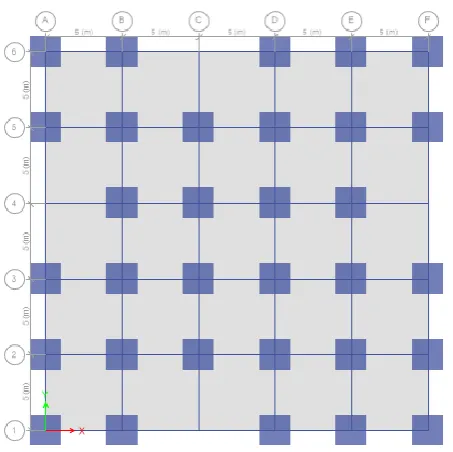
The structure considered here is a residential building with plan dimension of 25m×25m.In the present study a 10,15,20,25,30 storey RC structure with floating columns at exterior position in seismic zone IV is consider for analysis. The height of each storey is 3m and bay spacing in both direction is 5m.For wind load IS: 875 1987 part-3 is used and IS: 1893(part-1) 2002 is used for seismic loadings and IS: 14687 1999 is used for construction sequence analysis.
[image:3.595.320.547.78.304.2]Table-2: Structural data of RC framed structure
Fig.-2: Plan view with floating column at exterior side of frame
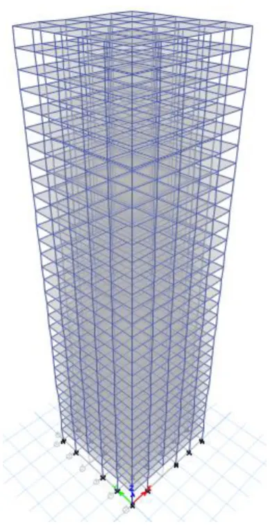
Fig.-3: Elevation of typical 30 storey building Dimension of building 25m×25m
Number of stories 10,15,20,25,30. Height of each storey 3m Height of ground floor 4.3m
Dimension of beam 300×450mm Dimension of transfer
girder 300×1800mm
Dimension of columns 2000×2000mm Dimension of floating
column 230×600mm
Thickness of slab 150mm Thickness of exterior wall 230mm Thickness of interior wall 115mm Seismic zone IV(Delhi)
Zone factor 0.24
Importance factor 1
Response reduction factor 3
Live load 3kN/m2
Floor finish 1kN/m2
Live load on roof 1.5kN/m2 Density of masonry wall 19kN/m3 Thickness of shear wall 300mm
Type of soil Medium
Wind speed 47m/s
Windward coefficient 1.25 Leeward Coefficient 0.5
Risk coefficient 1
Topography Coefficient 1
Grade of steel Fe550
© 2018, IRJET | Impact Factor value: 6.171 | ISO 9001:2008 Certified Journal | Page 818 Fig.-4: 3D –View of 30 Storey building
6. RESULTS AND DISCUSSION
Displacement of transfer girder at different cases:
Table-3: Displacement of TG for without SW structure
Table-4: Displacement of TG for SW at core structure
Storey 10 15 20 25 30
CA 2.93 1.87 3.99 4.48 2.61 CSA 2.77 1.75 3.75 4.73 2.79 Wind A. 2.66 1.68 3.63 4.08 2.17
[image:4.595.310.557.373.541.2]Table-5: Displacement of transfer girder for SW at Corner structure
Table-6: Displacement of transfer girder for SW at periphery structure
Storey 10 15 20 25 30
CA 2.98 3.66 2.72 2.77 1.7 CSA 2.8 3.65 2.65 2.78 1.57 Wind A. 2.72 3.67 2.57 2.77 1.57
From above tables, the displacement of transfer girder for storey 10,15 and 30 is greater for conventional analysis. For storey 20 and 25 ,displacement of transfer girder is greater by construction stage analysis.
Chart-1:Bending moment in TG for without SW structure
Chart-2: Bending moment in TG for SW at core structure
Storey 10 15 20 25 30
CA 2.04 1.54 4.63 2.17 3.6 CSA 2.11 1.5 4.12 2.3 3.57 Wind A. 2.64 1.46 3.83 1.93 3.35
Storey 10 15 20 25 30
[image:4.595.312.556.578.740.2]© 2018, IRJET | Impact Factor value: 6.171 | ISO 9001:2008 Certified Journal | Page 819
Chart-3: Bending moment of TG for SW at corner
Chart-4: Bending moment of TG for SW at periphery
From above chart, its clear that bending moment is maximum for conventional analysis and then for wind analysis. For safety of structure, building is design for conventional analysis considering earthquake forces.
7. CONCLUSION
a) Transfer girder give less bending moment at 10 and 20 storey cases, when shear wall provided at core.
b) Transfer girder give less bending moment at 15 and 30 storey cases, When shear wall provide at corner.
c) Transfer girder give less bending moment at 25 storey case, for without shear wall.
d) The displacement of transfer girder is less at 20 and 10 storey cases, when shear wall provide at core.
e) The displacement of transfer girder is less at 15 and 25 storey cases, for without shear wall.
f) The displacement of transfer girder is less at 30 storey case, when shear wall provide at periphery.
g) In most of storey cases, result of conventional analysis is critical and which is adopted for further procedure.
REFERENCES
[1]. Tabassum G. Shirhatti, Vanakudre S.B. , “The effects of P-delta and construction sequential analysis of RCC and steel building with respect to linear static analysis”, International Research Journal of Engineering and Technology, volume:02, issue:04, July-2015, pp:501-505.
[2]. Viji R. Kumar, Binol Varghese, “Effect of construction sequence analysis along with p-delta and material non linearity on floating column structure”, International Research Journal of Engineering and Technology, volume:04, issue:05, May-2017, pp:1946-1949.
[3]. Yousuf Dinar, Munshi Md. Rasel, Muhammad Junaid Absar Chowdhury, Md. Abu Ashraf, “Chronological construction sequence effects on reinforced concrete and steel buildings”, International Journal of Engineering and Science, volume:03, issue:01, December-2014, pp:52-63.
[4]. Meghana B.S, Sadashiva Murthy T.H, “Comparison of linear static analysis and construction sequence analysis on multi-storey building with RC floating column resting on RC and composite transfer girders”, International Journal of Engineering Trends and Technology, volume: 36, number:07, June-2016, pp:343-346.
[5]. Vignesh Kini K., Rajeeva S. V., “Comparison of response spectrum analysis of RC and steel-concrete composite multi-storey building with floating columns”, International Journal of Reasearch in Engineering and Technology, volume:06,issue:05,May-2017, pp:63-68.
[6].R. Pranay, I.Yamini Sreevalli, Er. Thota. Suneel Kumar, “Study and comparison of construction sequence analysis with conventional lumped analysis using Etabs”, Civil Engineering Systems and Sustainable Innovations, ISBN: 978-93-83083-78-7, pp: 220-228.
[7]. Sri Harsha B and Vikranth J, “Study and comparison of
construction sequence analysis with regular analysis by using ETABS”, International Journal of Research Sciences and Advanced Engineering, volume:02, issue:08, October-December-2014, pp:218-277.
[8]. Meghana B.S, Sadashiva Murthy T.H, “Effect of floating