PARIS RESEARCH LABORATORY
d i g i t a l
March 1992
17
17
Inferring Graphical Constraints
with Rockit
Solange Karsenty
James A. Landay
Chris Weikart
Publication Notes
This report also appears in Human Computer Interaction: Proceedings of HCI’92, University of York, U.K., September 1992. A short videotape demonstrating this work is available. Information can be obtained from the librarian at PRL.([email protected])
For correspondence, Solange Karsenty and Chris Weikart may be contacted at the following address:
Digital Equipment Corporation Paris Research Laboratory 85, avenue Victor-Hugo 92563 Rueil-Malmaison Cedex FRANCE
[email protected] [email protected]
James Landay was a research intern at Digital’s Paris Research Laboratory from June to September 1991. For correspondence, he may be contacted at the following address:
Carnegie Mellon University School of Computer Science 5000 Forbes Ave.
Pittsburgh, PA 15213 USA
c
Digital Equipment Corporation 1992
This work may not be copied or reproduced in whole or in part for any commercial purpose. Permission to copy in whole or in part without payment of fee is granted for non-profit educational and research purposes provided that all such whole or partial copies include the following: a notice that such copying is by permission of the Paris Research Laboratory of Digital Equipment Centre Technique Europe, in Rueil-Malmaison, France; an acknowledgement of the authors and individual contributors to the work; and all applicable portions of the copyright notice. Copying, reproducing, or republishing for any other purpose shall require a license with payment of fee to the Paris Research Laboratory. All rights reserved.
Abstract
Rockit is a system that identifies the possible graphical constraints between objects in a
two-dimensional scene and allows the user to choose and apply the desired constraints quickly and easily. Rockit looks for intersections between the position of a designated object and the
gravity fields of other objects to determine the possible constraints. These candidate constraints
are passed to a rule system that encodes some simple knowledge about how graphical objects normally interact and can thus be constrained to one another. The rules are used to determine the most likely constraints to be applied between the designated object and the other objects in the scene. As the user manipulates the object, the object will gravitate towards the most likely constraint scenario. The inferred constraints are indicated by the creation of graphical and sonic feedback objects. Rockit makes it easy to try other likely scenarios by simply pressing a key, causing the system to cycle through the other possibilities.
R ´esum ´e
Rockit est un syst`eme qui permet d’inf´erer des contraintes graphiques dans une sc`ene contenant
des objets graphiques `a deux dimensions. Ces contraintes peuvent rapidement et facilement ˆetre choisies par l’utilisateur, puis appliqu´ees. Rockit consid`ere les intersections entre la position de l’objet selectionn´e, et les champs de gravit´e dont sont munis tous les objets, ceci afin de determiner une liste de contraintes possibles. La liste ainsi construite est ensuite utilis´ee par un syst`eme de r`egles. Ces r`egles decrivent la fa¸con dont les contraintes sont usuellement appliqu´ees entre les objets, et permettent ainsi de d´eterminer les contraintes les plus plausibles. Lorsque l’utilisateur manipule l’objet s´electionn´e, celui-ci est attir´e dans une direction correspondant au sc´enario de la contrainte choisie par le syst`eme de r`egles. Les contraintes ainsi inf´er´ees sont mises en ´evidence grˆace `a des objets sp´ecialis´es qui peuvent ˆetre `a la fois graphiques et sonores. De plus, Rockit permet `a l’utilisateur d’essayer successivement d’autres sc´enarios. Pour cela, l’utilisateur tape sur une cl´e du clavier, et Rockit montre, par ordre d´ecroissant de potentiel, les contraintes possibles.
Keywords
Geometric constraints, graphical editors, inferencing, interaction techniques, direct manipula-tion, user interfaces, sonic feedback, audio.
Acknowledgements
We would like to thank James Aspnes, Michel Beaudouin-Lafon, Stewart Clamen, Michael Gleicher, Bruce Horn, David Kosbie, David Kurlander, Brad Myers, Greg Nelson, Francis Prusker, Marc Ringuette, and Hank Wan for improving the readability of this report. We would also like to thank Michel Gangnet for the helpful discussions and comments on this work.
Contents
1 Introduction 1
2 User interface and examples 2
3 Constraints and feedback 4
3.1 Supported constraints : : : : : : : : : : : : : : : : : : : : : : : : : : : 6
3.2 Combining sonic and graphical feedback : : : : : : : : : : : : : : : : 7
4 Inferring and solving constraints 8
4.1 Gravity fields : : : : : : : : : : : : : : : : : : : : : : : : : : : : : : : : 9
4.2 Rule system : : : : : : : : : : : : : : : : : : : : : : : : : : : : : : : : 10
4.3 Constraint solver : : : : : : : : : : : : : : : : : : : : : : : : : : : : : : 11
5 Related work 12
6 Status and future research 13
7 Conclusion 14
References 15
Inferring Graphical Constraints with Rockit 1
1 Introduction
Graphical constraints define relations among graphical objects that must be automatically maintained by an underlying system. The automatic maintenance of these relations has become important in increasing the functionality of graphical editors and user interface builders. Yet this increase in functionality forces the users of these tools, usually program or interface designers, to perform the difficult task of specifying the constraints. Constraints in these systems are generally specified by writing mathematical equations that define the relations which must hold.
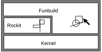
The purpose of Rockit, which stands for a Rapid graphical Object Constraint identifier using Knowledge Inferencing Techniques, is to automatically identify the possible graphical constraints between objects in a scene and to allow the user to choose and apply the desired constraints quickly and easily. Rockit is a component of a larger system, Rollit [15], an interface and application builder for two dimensional graphical applications that concentrates on building the data view, also known as the domain adaptor [31] of an application (see Figure 1).
Rockit
[image:9.612.214.377.301.385.2]Kernel Funbuild
Figure 1: Rollit components
Rockit is implemented as a function of the graphical editor, Funbuild, which allows the user to create both primitive and composite application objects by direct manipulation. The user creates (possibly hierarchical) graphical objects and applies constraints to them, with the help of Rockit. Both Rockit and Funbuild rely on the system kernel, which manages the data structures and constraints. Typical application objects include diagrams, circuits, and flowcharts. The targeted applications are graphical editors, though Rollit is not restricted to this kind of application. One of the main goals of Rollit is to provide powerful mechanisms for the creation, representation, and manipulation of data within the application’s functional core. In this document, the term user will refer to the application designer – a user of Funbuild – as opposed to the end-user of the application being designed.
Rockit uses a rule system that encodes some simple knowledge about how graphical objects are related and thus how they can be constrained among one another, as in Peridot [20, 21]. When a user creates or modifies an object, Rockit uses object-defined gravity fields to filter out unlikely constraints. The remaining candidates are passed on to the rule system, which prioritizes the possible constraints to be applied between the selected object and the other objects in the scene. As the user manipulates the object, it will gravitate towards the most likely constraint scenario. Rockit makes it easy to try other likely scenarios by simply pressing
2 Solange Karsenty, James A. Landay, and Chris Weikart
a key, causing the system to cycle through the most likely possibilities, as in [10, 19].
One unique feature of Rockit is that it usually infers the desired constraint very quickly by using gravity fields to filter out unlikely possibilities. Users do not need to continually answer questions [20], produce multiple snapshots [16], or specify constructor objects [3, 10, 18, 19]. In addition, the user does not need to specify the constraints explicitly as in many previous systems [5, 13, 22]. Another unique feature of our system is that it allows developers to dynamically change the rule conditions and rule ordering that determine which constraints are most likely, and thus make applications behave differently depending on end-user runtime actions. For instance, this would allow Rockit to automatically improve the quality of its inference based upon similar actions performed repeatedly.
The next section describes the user interface to the graphical editor, Funbuild, and gives examples of how Rockit is used within this editor. In the third section we describe the constraints supported by Rockit, while the fourth section explains how gravity fields interact with the rule system to infer these constraints. The fifth section outlines related work and explains how Rockit differs. Finally, we describe the current status of the system and our plans for future research.
2 User interface and examples
Funbuild is the interactive front-end to Rollit. It allows the user to create and edit primitive and composite application objects by direct manipulation, in the spirit of a graphical editor such as MacDraw [1]. In general, an application object is made up of several primitive objects that are constrained among one another. Rockit is used to help specify these constraints during the creation and editing of these objects.
When automatic constraint inferencing is turned on, Rockit will try to infer the most likely graphical constraints by examining the currently selected object, the position of this object with respect to other objects close by, and known relations between the selected object and other objects in the region. These relations express both the necessary conditions for a constraint to be inferred and a ranking among the types of constraints that can be inferred between the current object and other types of objects.
As the user drags an object, Rockit may infer one or several constraints. The user then observes the dragged object moving towards the most likely scenario. This gravitation does not involve
warping the mouse pointer; the pointer continues to travel as directed by the user, but the
object may be offset slightly. This offset is the result of a gravitational force applied to the object. The gravity-induced component of the object’s movement is recalculated every time the mouse pointer moves. In contrast to the traditional usage of gravity in user interfaces, as first defined by Sketchpad [28], gravity in Rockit more closely resembles the natural attraction between physical objects, rather than just the sudden snapping of one object to another when they are at some fixed distance from each other.
Inferring Graphical Constraints with Rockit 3
In addition to gravitation towards the most likely constraint scenario, Rockit provides feedback about the kind of constraint that is being proposed by creating appropriate feedback objects. These feedback objects are both graphical (similar to the user-selected alignment objects in
Snap-Dragging [3]) and sonic (that is, they can have an associated sound). The user can accept
[image:11.612.161.431.153.381.2]a constraint by snapping the dragged object to the feedback object; otherwise the constraint is not accepted.
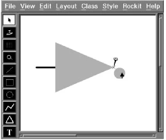
Figure 2: As the user drags the circle towards the triangle, Rockit infers a connection constraint.
If at any time the user is unhappy with the inferred constraints, hitting the cycle key will identify the next most likely set of constraints. In addition, the user can snap to one of the feedback objects and then indicate to the system that no constraint should be applied, thus allowing the use of simple Snap-Dragging for precise, unconstrained placement.
For example, Figure 2 shows how to create an inverter for a CAD application. First, a triangle is created using Funbuild’s toolbox. Next, a circle is made. As the circle is dragged towards the right vertex of the triangle, it eventually enters one of the triangle’s gravity fields. At this point, Rockit uses its rule system to infer that we could connect the circle – more specifically, an object-defined site closest to the mouse position, which in this case is the center of the circle – to the triangle. Rockit creates a feedback object, a nail on the triangle’s right vertex, and activates its gravity field to indicate this inferred constraint. Entering the gravity field produces an unobtrusive sound which sustains as long as we remain inside the gravity field. Furthermore, while the circle is being dragged, the gravity causes the circle to begin to “gravitate” towards the target location. The gravitation makes it easier to guide the circle towards the vertex and to then snap it into place, thus indicating our acceptance of the proposed constraint.
4 Solange Karsenty, James A. Landay, and Chris Weikart
The next example illustrates the creation of a simple slider. The slider is made up of a box, a line with an “elevator” moving along it, and two pieces of text to indicate the lower and upper bounds of the slider’s value. We want to connect the line’s endpoints to the top and bottom of the box along its centerline, and we want the elevator to move vertically along the line. We also want the text objects to be attached to the top-right and bottom-right corners of the slider.
First we create the box. Then we use the line tool and start dragging a thick line from a point on the top of the box to a point near the bottom of the box. At this point, no constraint is applied on the initial endpoint. While dragging the other endpoint, Rockit will infer that we want to connect the line to the box and will display a feedback object at the connection point as in the first example (see Figure 2). We then snap it to the bottom of the box, thus indicating our acceptance of the proposed constraint. In order to similarly connect the initial endpoint to the box, we select it and stretch it towards the top of the box. Again, Rockit will infer a connection constraint and we can snap the endpoint into place.
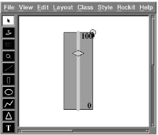
Next we create the elevator – a polygon that will be allowed to slide – and drag it inside the box. As the dragged point of the polygon approaches the center of the line, Rockit will infer that these two objects should be connected. We can easily ignore that constraint by dragging the polygon towards the upper end of the line. At this point, Rockit will infer that we would like to vertically align the two objects. Rockit will create a feedback object – a vertical dashed line going through the axis line (see Figure 3). This line has a gravity field surrounding it with a gravity function that only affects the x coordinate of objects entering it. We can now easily drag the polygon towards the dashed line and snap it into place. The elevator is now constrained to slide vertically along this line.
We now create two text objects, a “0” and a “100”. We want to connect them to the lower-right and upper-right corners of the box, respectively. If we drag the “0” below the box, Rockit infers that it should be centered below the box. We can easily ignore that constraint by dragging the text towards the right corner of the box. At this point, Rockit will infer that we would like to align the text with the bottom of the box. Since this is not yet what we want, we can hit the cycle key and see the next guess. Rockit finally proposes to connect the text to the box. After snapping the text into place, it will be constrained as desired. Similarly, we can connect the second text object to the upper-right corner of the box (see Figure 4).
3 Constraints and feedback
Constraints are relations that must hold at all times and are generally maintained by an underlying system known as a constraint solver. Traditionally constraints have been represented as a combination of a predicate, used to test whether the constraint currently holds, and some methods that can be executed to satisfy the constraint [4]. In Rockit, as in [5], the methods to satisfy a given constraint are deduced automatically from the predicate.
Two different types of graphical feedback are given by Rockit. The first kind is given when the system guesses a possible constraint, while interaction is in progress. The second is given when the user indicates acceptance of the guessed constraint by snapping the dragged object.
Inferring Graphical Constraints with Rockit 5
Figure 3: As the user drags the polygon towards the axis line, Rockit indicates that it has inferred a vertical alignment constraint between the two objects.
Figure 4: After the user snaps the text onto the corner of the box, Rockit indicates that the user has accepted a connection constraint between the corner of the box and the text.
[image:13.612.162.430.376.606.2]6 Solange Karsenty, James A. Landay, and Chris Weikart
For instance, if the user drags an object towards another object to which it can connect, the dragged object will gravitate towards the fixed object. At this stage, a guess feedback object is displayed on the fixed object. If the user drags the object even closer, the dragged object will snap to the feedback object, and an accept feedback object will be both shown and heard. This indicates that the user has accepted the guess, although it can still be refused by pressing a designated reject key.
3.1 Supported constraints
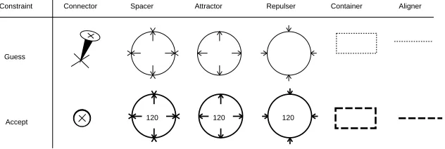
The system currently attempts to identify six different kinds of constraints between objects: connectors, spacers, attractors, repulsers, containers, and aligners. Each of these constraints is indicated to the user by the creation of a graphical feedback object (see Figure 5). A user can add new types of constraints by using facilities available in Rollit’s programming environment.
Guess
Accept
Constraint Connector Spacer Attractor Repulser Container Aligner
[image:14.612.153.469.263.369.2]120 120 120
Figure 5: Guess and accept graphical feedback objects
Spacers specify a fixed distance between two points. Repulsers specify a minimum allowable distance, while attractors specify a maximum distance between two points. Spacers are commonly used to maintain precise measurements in drawings. By allowing the two points to occur on the vertices of the same object, the object can be constrained such that stretching of a given dimension is not permitted. Repulsers are useful in defining the minimum spacing between a group of objects that may be resized. An example of this is in defining the minimum spacing between buttons in a window.
Connectors, a special case of spacers, specify that two points must be coincident. A connector constraint is used to attach the circle to the triangle in the inverter shown in Figure 2.
Containers specify that either the extent or the center of one object must remain within the extent of another. Containers are useful for hierarchical design in circuit editors, for instance, since they allow the specification of a box in which logic gates must remain.
Aligners allow the vertical or horizontal alignment of points. A vertical aligner was used to create the slider shown in Figure 3.
By default, all constraints are symmetrical. This means that if two objects are constrained, neither of them masters the other. In other words, the arithmetic equations describing the
Inferring Graphical Constraints with Rockit 7
constraints are not oriented. However, there are many cases where one needs to fix the direction in which the constraint should be solved. For instance, if objects A and B are vertically aligned, we may want to have B’s alignment depend on A, but not the converse. As a result, B cannot move horizontally, while moving A horizontally changes B’s horizontal position in order to satisfy the constraint. All of the constraints in Rockit can be oriented by defining the master object and the slave object of the constraint, as in Alien [6]. For example, oriented attractors, known as “annotators”, are often used for labeling objects with a piece of text. This means that the text – the slave – must follow the object if it moves, yet the text can still move independently within a fixed distance from the object.
Spacers, attractors, and repulsers typically have low priority in Rockit’s rule system, since their gravity field regions are infinite. Such constraints are usually proposed to the user after cycling through several other guesses. When Rockit guesses such a constraint, the user can switch to an accept state by dragging the object to the corresponding object’s site. Rockit then shows the accept feedback object, which displays the current distance between the two sites. Rockit remains in this state until the user either (a) accepts the constraint by releasing the dragged object, (b) cycles to the next guess, or (c) hits the cancel key. If accepted, the constraint is created with the current distance between the two objects.
The constraint solver is called during every user action, and therefore the user always sees a consistent scene. For instance, suppose that the user drags an object in a direction that would cause some existing constraints to become unsatisfied. At that point, the dragged object “decouples” from the pointer (stops moving). This type of feedback informs the user of a conflict. The user can either abort the action or accept the most recent position of the object that still satisfies the existing constraints.
3.2 Combining sonic and graphical feedback
Purely graphical feedback is problematic, largely because it is not always easily distinguishable from the graphical objects themselves. There is no graphical style attribute, such as line thickness or dash style, “reserved” for feedback objects. Since the nature of the task at hand is to construct graphical applications, we need an orthogonal sensorial dimension: audio [14].
We have associated a sound property with each feedback object. This property is activated by default when the feedback object appears on the screen. As a result, a continuous sound is produced while an object is dragged through the region of a gravity field. When a constraint is accepted – for example, when an object is snapped to the edge of a guess feedback object – a brief “clack” sound is played. The type of constraint, which may have been graphically symbolized by only a dashed line, is now also represented by a sound. With six constraint types and two states for each, there must be twelve unique sounds. Naturally, the two sounds associated with a specific constraint type are related to each other and must therefore be “sonically similar”.
Since our paradigm does not directly correspond to a “real-world” situation, as in Arkola [9], we needed to find sounds that would be the most helpful for the largest number of users.
8 Solange Karsenty, James A. Landay, and Chris Weikart
Obviously, such subjective judgements can only be vindicated by experience. We have collected sounds from two sources: some natural sounds were sampled and other sounds were recorded from a synthesizer. For sampled sounds, we started by recording speech because it was an obvious kind of feedback that did not require any learning. We used such phrases as “vertical alignment!” or “spacer!”. This technique revealed two problems: such sounds were not intelligible when mixed and sustain was not possible unless looping on the word (in our system, a sustained sound is required while an object remains in the region of a gravity field.)
Mixing sounds causes a major difficulty. Users frequently activate as many as two or three potential constraints, triggering multiple sounds simultaneously. By carefully choosing the sounds and ensuring that pitches combine consonantly, we can make the feedback understandable and pleasant to listen to. We can also adjust the volume to render the intensity of the gravity field (which usually varies with distance). This particular aspect was never reflected clearly through the graphics alone, although it could be detected through the “feel” of the gravitation towards the feedback objects. As a result, we have observed among our users a significant increase in the complexity of their graphics manipulations, and therefore the scenes being designed. Audio allows the user to choose more easily among several constraints.
In a previous implementation, we experimented with sound interleaving instead of sound mixing. That is, sounds were played successively and repeatedly for a time proportional to the intensity of the gravity field. This technique was abandoned because interleaved sounds were not accurate enough. Furthermore, the human ear can easily capture and understand mixed sounds if they are carefully designed, as discussed above. We found, for instance, that the attack, sustain, and decay of a sound can express fine grained states of interaction that can help distinguish mixed sounds.
While it is obvious that sound conveys useful information in everyday life, it is not always clear how audio can be used in the computer to improve user interfaces. It is still often considered annoying, especially in a group context. Nevertheless, within the context of our experiment, audio with graphics is easier to use than the purely graphical alternative.
4 Inferring and solving constraints
Rockit simplifies the task of inferring constraints by relying on both graphical and written relations. The graphical relations are expressed by both the shapes and strengths of gravity fields, while the written relations are defined by a simple rule system.
Rockit analyzes a designated object and a set of candidate objects in the same scene. This process uses gravity fields, which are attached to every object in the scene, to filter the set of objects to consider. Rockit then uses its rule system to return an ordered list of possible constraints between the first object and the candidate objects, ranked by a confidence value indicating how “desirable” each constraint is.
The inference process is initiated whenever an object is created or modified (i.e. moved or resized) or when the user chooses to identify the possible constraints on a selected object. In
Inferring Graphical Constraints with Rockit 9
this section, we explain the inference process and give a brief overview of the constraint solver.
4.1 Gravity fields
Each object in a scene has gravity fields associated with it. A gravity field consists of:
a size and shape, or region
a potential function that describes how it attracts or repels objects contained in the
region.
A gravity field is said to be enclosing when its region contains the dragged point. Rockit can limit the number of possible constraints to be examined by the rule system by first building the set of enclosing gravity fields and then inferring constraints only with respect to the enclosing fields.
A gravity field is said to be active when its function is applied to the currently selected object lying within its region. After the rule system has inferred the possible constraints, the n most likely candidates will have their gravity fields activated (n defaults to one, but can be adjusted). Dragging an object through multiple overlapping active gravity fields results in a composite displacement for each mouse move, according to the average of the contributions of all the fields.
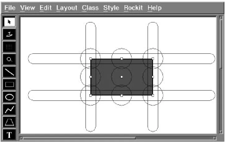
Each object in a scene has points defined on it, known as constraint sites, to which constraints can be attached. These points are usually important features of the object, such as vertices, midpoints of line segments, or centers of circles. Figure 6 shows these points highlighted. There can be multiple constraint sites defined on the same geometrical point. Each constraint site has a constraint type, guess and accept feedback objects, a snap horizon, and a gravity
field associated with it. The type specifies the kind of constraint the site can be involved in.
For instance, in Figure 6, there are two constraint sites on each of the midpoints of the line segments that define the rectangle: a constraint site of type connector and another one of type
aligner.
The snap horizon (not shown in Figure 6) defines a region within which dragged objects should snap to the guess feedback object associated with the constraint site defining that region. Snapping to the feedback object indicates acceptance of the proposed constraint involving that site.
The shape, size, and force of the gravity field are maintained by each site. The rule system will try to infer a constraint between two sites only if the site being dragged lies within the gravity field region of the other site.
The gravity field region is usually a symmetrical area around the site. These regions can be made visible within the editor. Figure 6 shows two kinds of regions around the sites: a circular area for connectors and an elongated area for aligners, both centered on their constraint site. In order to allow alignment constraints for any distance, the size of the elongated region may be made long enough to cover the entire scene. The rectangle in this example has thirteen
10 Solange Karsenty, James A. Landay, and Chris Weikart
Figure 6: Gravity field regions for connectors and aligners
constraint sites. These regions can be redefined interactively by the interface designer, using the mouse to either stretch an existing shape or to draw a new shape.
The function defining the gravity force can be dynamically set for each site. An object that is very unlikely to be involved in a constraint with the selected object can set its associated force function to one that returns only negative values. By allowing dynamically-defined gravity fields, including infinitely negative gravity, the user is free to implement constraints that have runtime semantics, as in [12]. For example, this could be used in a circuit editor to disallow connecting wires that have different voltages. As the user drags the first wire close to the second wire, a negative gravity field could be activated to keep them apart.
4.2 Rule system
Rockit uses a simple rule system along with the gravity magnitudes to choose among the possible graphical constraints. Our system allows the application to dynamically change the conditions that determine which rules to execute and thus lets applications behave differently depending on runtime actions of the end-user.
The rules are stored as tuples of the form:
(constraint, conditions, rank function)
When a rule’s conditions match the current situation, its rank function is then calculated. The rank function, which can be defined separately for each rule, is used to order the applicable constraints by how “good” that constraint would be in the current situation. Its arguments are made up of simple graphical attributes of the scene, such as the magnitude of the gravity
Inferring Graphical Constraints with Rockit 11
between the two constraint sites.
An example of a rule is:
constraint(VerticalAligner(A;B)),
conditions(IsAny(A);IsAny(B);A:xB:x;A:y6B:y),
rank function(abs(A:x B:x))
This rule vertically aligns any two objects (say a rectangle and a line) which are already close to being vertically aligned, but are not close enough to be connected.
These are the steps involved in the process of inferring the constraints:
As the user drags an object, Rockit identifies a specific point on this object. This point is
by default its middle point, unless the user has intentionally grabbed another point. This point may have a number of constraint sites attached to it. These sites form the dragged object’s set of sites, D.
Rockit then builds the set of constraint sites, S, whose gravity fields are enclosing. These
are the sites associated with gravity field regions that contain the dragged point.
Rockit then builds an initial set of constraints by considering all pairs(x;y), where
x2D;y2S, and Type(Constraint(x))=Type(Constraint(y)).
These constraints are passed to the rule system. The rule system ranks them and returns
a list sorted by decreasing rank.
Rockit picks the first n constraints in this list, n defaulting to one, activates the associated
gravity fields, and shows feedback for each one.
At this point, the user can either accept one of the constraints by snapping to the feedback
object or cycle through the next n constraints in the list.
4.3 Constraint solver
Rockit has been designed independently of the constraint solver. The constraint solver that we have implemented works by local propagation. The underlying data structure is a data graph made up of nodes that are graphical objects and edges that are constraints. If constraints are not initially oriented, the solver will arbitrarily choose an orientation during solving. The solver works as follow: it constructs a DAG from the data graph and chooses a root of the DAG as the “master” node. This master node is usually the object being manipulated by the user. The user expects this object to follow the mouse position and affect other objects in the scene according to the constraints applied between them (to do otherwise would be confusing). When a loop is encountered in the construction of the DAG, the solver will fail if that constraint cannot be satisfied without undoing other previously satisfied constraints.
We expect to improve the solver and to eventually implement a more powerful algorithm, such as Delta–Blue [7] or the algorithm described in [8]. This has become necessary because of scenes that include lots of constraints or situations where the solver fails on relatively simple cases. For instance, depending on the arbitrary orientation initially given to the constraints, the current solver may not succeed.
12 Solange Karsenty, James A. Landay, and Chris Weikart
5 Related work
Early attempts at improving computer-based illustrators suggested the use of constraints to maintain relationships between graphical objects in illustrations. Though the use of constraints in drawing programs [13, 22, 28, 30] and graphical user interfaces [4, 17, 20, 23] is not new, successful attempts at automatically inferring graphical constraints have only more recently been gaining attention. One such attempt has been made in scene beautification [25]. Beautification tries to “clean up” a completed drawing that has been roughly sketched by satisfying the inferred constraints in the scene. This batch method has several drawbacks for our application. Often, it does not infer all of the proper constraints on the first attempt and the operation of beautifying is not idempotent, thus leaving users in the dark on how many times they need to execute the beautifier to achieve the desired results. Trying to infer all possible constraints in a scene at once is much harder than trying to infer only the constraints between one object and the rest of the scene. More importantly, by getting user assistance as each constraint is placed, Rockit further improves the speed at which it can infer the correct constraints. Beautification is therefore both much slower and less accurate, making it inappropriate for an interactive editor.
Another approach to constraint identification involves taking multiple snapshots [16] of a scene. In this type of system the initial drawing is considered fully constrained after the first snapshot. After modifying the drawing, a new snapshot is taken. The differences between the two snapshots are analyzed to see which degrees of freedom the objects in the scene are allowed to have. This process can be repeated multiple times until the desired constraints are in place. One problem with this method is that the system may infer an incidental constraint, that is, a constraint that was evident in the snapshots, yet not intended by the user. An incidental constraint may leave the constraint system unsolvable when the user tries to manipulate the system. In order to keep the user from having to confront this confusing problem, we avoid having our constraint system enter unsolvable states. We achieve this by solving the system at every mouse move, while the user is dragging an object. Therefore Rockit will only accept constraints which do not conflict with existing constraints.
Another recent system infers constraints by observing which positioning operations are used as individual objects are moved [10]. This system extends Snap-Dragging [3] by inferring and remembering the underlying constraints specified by the Snap-Dragging operations. In addition, it combines a differential approach with the technique of constrained dynamics to ensure that it will always be possible to solve the constraint system since the system is never allowed to move to an unsolvable state. This system still requires the user to specify the positioning operations, whereas we infer the positioning operations automatically by the use of gravity fields and a rule system.
The main motivation of semantic snapping [12] is to provide semantic feedback at the lexical (user input) level. This is achieved through predicate functions called when snapping onto sites. For instance, consider an object with a maximum fan-in/fan-out. Connecting to that object invokes a predicate function that tests the number of connections. When the maximum fan-in/fan-out is exceeded, the site provides feedback to the user, such as a message explaining
Inferring Graphical Constraints with Rockit 13
why they cannot make the desired connection. In order to resolve ambiguous snaps, the user can reject a snap by pushing a button, which causes the site to be deactivated. This is somewhat similar to our approach, except that we rely on the rule system to give more fine-grained control over how to resolve these ambiguities. The main difference is that we can consider several constraints on one point, each with its own independent gravity field. We do not deactivate a site, but we consider the priorities of the constraints, as expressed by the rule system, to choose the most likely constraint. Semantic feedback is supported within Rollit itself and is thus specified at that level rather than in Rockit. Graphical constraints are a special case of Rollit’s constraints, which allow semantic feedback to be achieved through pre- and post-conditions on the creation and deletion of constraints and application objects.
Rule-based systems have been used previously in helping to create both drawings and user interfaces [29], as well as in design tools for building models to describe and position shapes [11]. The Visualization-System [26] used heuristics to allow artists to automatically transform drawings according to the rule selected by the artist. The system allowed the exploration of new artistic concepts, but it required the user to select which rule to apply.
Peridot [20] and Druid [27] both store simple rules about the relationships between objects in
graphical user interfaces. Even though they use inferencing to choose a rule, both require the user to continually answer questions to decide if the inferred rule is the correct one to apply. By automatically inferring constraints and integrating this with the basic drawing metaphor, the user interface to constraint placement is much improved and therefore allows further use of this powerful mechanism.
6 Status and future research
Rockit is implemented in C++ 2.0, as is the rest of Rollit. The graphics and event handling are provided by the Xtv [2] graphical toolkit. Rockit is integrated with the Funbuild editor, which uses the Motif [24] toolkit. Funbuild allows the developer to build application object classes that are typically composite, constrained objects. Rockit allows interactive specification of these constraints.
Some areas of Rockit must be investigated further to see if more powerful functionality can be added without undue difficulty for the user. One area of possible investigation is in conflicting constraint resolution. Currently, we do not allow the user to create conflicting constraints. An alternative solution would be to allow this, and then to partition the conflicting constraints using a preference level. Constraint solvers have been developed that can solve constraint systems with this type of hierarchy [7, 8]. Another area of investigation is in tuning the types and ordering of the rules. This could be done through a rule browser that would allow the developer to easily change the conditions and ordering of the rules by direct manipulation.
Rockit could be made user adaptive. Since it is possible to modify the rule system dynamically, Rockit could profit from a history of the user’s actions. For instance, in the example where the user is placing the second text object on the slider (see Figure 4), there are two inferences that are plausible. The first would be to align the text with the box and the second would be
14 Solange Karsenty, James A. Landay, and Chris Weikart
to connect the two objects together. Rockit could rate the latter option as more likely since we had recently applied this type of constraint.
Another important area to investigate is extending the constraints themselves. This would include making more complex constraints, such as alignment along arbitrary angles, and extending the interface to allow the specification of constraints between more than two constraint sites. In addition, a facility to specify constraints on constraints would allow a simple specification of even more complex constraints, such as a constraint on the relative distances between pairs of points.
Finally, we would like to explore other forms of feedback, such as graphic style changes, animation, and more sophisticated sound effects. Rockit has been implemented in a way that easily allows a high degree of customization of its behavior, thus making it simple to examine different interaction techniques. Formal user testing is necessary to determine which kind of feedback is the most helpful in indicating to the user that a constraint is being guessed by the system.
7 Conclusion
The Rockit system described in this paper will help users to easily specify graphical constraints, thus speeding up the creation of Rollit applications. By using both gravity fields and rule-based methods, Rockit is able to vastly reduce the number of possible constraints it considers and is therefore able to propose constraints quickly. The use of multiple kinds of feedback allows users to easily decide whether the proposed constraints are what they intended. If not, Rockit’s cycling feature allows them to try other possibilities. This novel approach to constraint specification can be applied to other applications such as drawing programs, page layout, and CAD tools. In the future, we expect to learn more through additional user testing and to tune our system for improved efficiency.
Inferring Graphical Constraints with Rockit 15
References
1. Apple Computer Inc., 20525 Mariani Avenue, Cupertino, California 95014. MacDraw
User Manual (1987).
2. Michel Beaudouin-Lafon, Yves Berteaud, and St´ephane Chatty. Creating Direct Manip-ulation Applications with Xtv. In Proc. European X Window System Conference EX’90, pages 148–155 (November 1990).
3. Eric A. Bier and Maureen C. Stone. Snap-Dragging. Computer Graphics, 20(4):233–240 (August 1986). ACM SIGGRAPH’86 Conference Proceedings.
4. Alan Borning and Robert Duisberg. Constraint-Based Tools for Building User Interfaces.
ACM Transactions on Graphics, 5(4):345–374 (October 1986).
5. Alan H. Borning. Defining Constraints Graphically. In Human Factors In Computing
Systems: Proceedings ACM SIGCHI’86, pages 137–143, Boston, MA (April 1986).
Addison and Wesley.
6. Eric Cournarie and Michel Beaudouin-Lafon. Alien: a prototype-based constraint system. In Second Eurographics Workshop on Object Oriented Graphics, pages 93–114 (June 1991).
7. Bjorn Freeman–Benson, John Maloney, and Alan Borning. An Incremental Constraint Solver. Communications of the ACM, 33(1):54–63 (January 1990).
8. Michel Gangnet and Burt Rosenberg. Constraint Programming and Graph Algorithms. In Second International Symposium on Artificial Intelligence and Mathematics, Ft. Lauderdale (January 1992).
9. William W. Gaver, Randall B. Smith, and Tim O’Shea. Effective Sounds in Complex Systems: The Arkola Simulation. In CHI’91 Proceedings, Human Factors in Computing
Systems, pages 85–90. Addison Wesley (1991).
10. Michael Gleicher and Andrew Witkin. Creating and Manipulating Constrained Models. Technical Report CMU-CS-91-125, Carnegie Mellon University, School of Computer Science (January 1991).
11. Bernice Trefman Glenn. DESCRIPTOR: A Model for Describing Shapes that Infers Relations for Positioning Them. Master’s thesis, University of California, Los Angeles (1986). Architecture and Urban Planning.
12. Scott E. Hudson. Adaptive Semantic Snapping – A Technique For Semantic Feedback at the Lexical Level. In Human Factors In Computing Systems: CHI’90 Conference
Proceedings, pages 65–70, Seattle, WA (April 1990). Addison and Wesley.
16 Solange Karsenty, James A. Landay, and Chris Weikart
13. Devendra Kalra and Alan H. Barr. A Constraint-Based Figure-Maker. In Eurographics’90:
Proceedings of the European Computer Graphics Conference and Exhibition, pages 413–
424, Montreux, Switzerland (September 1990). North–Holland.
14. Solange Karsenty, James A. Landay, and Chris Weikart. Audio Cues for Graphic Design. In CHI’92 Posters and Short Talks Proceedings, pages 77–78, Monterey, CA (May 1992).
15. Solange Karsenty and Chris Weikart. Building the Domain Specific User Interface: Another Challenge. Submitted for publication (January 1992).
16. David Kurlander and Steven Feiner. Inferring Constraints from Multiple Snapshots. Technical Report CUCS-008-91, Department of Computer Science, Columbia University (May 1991).
17. John H. Maloney, Allan Borning, and Bjorn N. Freeman-Benson. Constraint Technology for User-Interface Construction in ThingLab II. In OOPSLA’89 Conference Proceedings, pages 381–388, New Orleans, LA (October 1989).
18. David L. Maulsby, Kenneth A. Kittlitz, and Ian H. Witten. Constraint-Solving in Interactive Graphics: A User-Friendly Approach. In Computer Graphics International’89, pages 305–318. Springer–Verlag (1989).
19. David L. Maulsby, Ian H. Witten, and Kenneth A. Kittlitz. Metamouse: Specifying Graphical Procedures by Example. Computer Graphics, 23(3):127–136 (July 1989). ACM SIGGRAPH’89 Conference Proceedings.
20. Brad A. Myers. Creating User Interfaces by Demonstration. Academic Press (1988).
21. Brad A. Myers and William Buxton. Creating Highly-Interactive and Graphical User Interfaces by Demonstration. Computer Graphics, 20(4):249–258 (August 1986). ACM SIGGRAPH’86 Conference Proceedings.
22. Greg Nelson. Juno, a Constraint-Based Graphics System. Computer Graphics, 19(3):235– 243 (July 1985). ACM SIGGRAPH’85 Conference Proceedings.
23. Dan R. Olsen Jr. and Kirk Allan. Creating Interactive Techniques by Symbolically Solving Geometric Constraints. In Proceedings of UIST’90, pages 102–107, Snowbird, UT (October 1990). ACM Press.
24. OSF, editor. OSF/Motif Programmer’s Reference. Prentice Hall (1990).
25. Theo Pavlidis and Christopher J. Van Wyk. An Automatic Beautifier for Drawings and Illustrations. Computer Graphics, 19(3):225–234 (July 1985). ACM SIGGRAPH’85 Conference Proceedings.
26. Laura Scholl. Heuristic Rules for Visualization. In Proceedings of Graphics Interface’85, pages 443–446, Montreal, Quebec (May 1985).
Inferring Graphical Constraints with Rockit 17
27. Gurminder Singh, Chun Hong Kok, and Teng Ye Ngan. Druid: a System for Demonstra-tional Rapid User Interface Development. In Proceedings of UIST’90, pages 167–177, Snowbird, UT (October 1990). ACM Press.
28. Ivan Sutherland. Sketchpad: A Man Machine Graphical Communication System. PhD thesis, Massachusetts Institute of Technology (January 1963).
29. Brad Vander Zanden and Brad A. Myers. Automatic, Look-and-Feel Independent Dialog Creation for Graphical User Interfaces. In Human Factors In Computing Systems: CHI’90
Conference Proceedings, pages 27–34, Seattle, WA (April 1990). Addison and Wesley.
30. R.M. White. Applying Direct Manipulation to Geometric Construction Systems. In
Computer Graphics International’88, pages 446–455. Springer–Verlag (1988).
31. The UIMS Tools Developers workshop. A Metamodel for the Runtime Architecture of an Interactive System. ACM SIGCHI Bulletin, pages 32–38 (January 1992).
PRL Research Reports
The following documents may be ordered by regular mail from: Librarian – Research Reports
Digital Equipment Corporation Paris Research Laboratory 85, avenue Victor Hugo 92563 Rueil-Malmaison Cedex France.
It is also possible to obtain them by electronic mail. For more information, send a message whose subject line [email protected], from within Digital, todecprl::doc-server.
Research Report 1: Incremental Computation of Planar Maps. Michel Gangnet, Jean-Claude Herv ´e, Thierry Pudet, and Jean-Manuel Van Thong. May 1989.
Research Report 2: BigNum: A Portable and Efficient Package for Arbitrary-Precision Arithmetic. Bernard Serpette, Jean Vuillemin, and Jean-Claude Herv´e. May 1989.
Research Report 3: Introduction to Programmable Active Memories. Patrice Bertin, Didier Roncin, and Jean Vuillemin. June 1989.
Research Report 4: Compiling Pattern Matching by Term Decomposition. Laurence Puel and Asc ´ander Su ´arez. January 1990.
Research Report 5: The WAM: A (Real) Tutorial. Hassan A¨ıt-Kaci. January 1990.y
Research Report 6: Binary Periodic Synchronizing Sequences. Marcin Skubiszewski. May 1991.
Research Report 7: The Siphon: Managing Distant Replicated Repositories. Francis J. Prusker and Edward P. Wobber. May 1991.
Research Report 8: Constructive Logics. Part I: A Tutorial on Proof Systems and Typed
-Calculi. Jean Gallier. May 1991.
Research Report 9: Constructive Logics. Part II: Linear Logic and Proof Nets. Jean Gallier. May 1991.
Research Report 10: Pattern Matching in Order-Sorted Languages. Delia Kesner. May 1991.
y
This report is no longer available from PRL. A revised version has now appeared as a book: “Hassan A¨ıt-Kaci,
Research Report 11: Towards a Meaning of LIFE. Hassan A¨ıt-Kaci and Andreas Podelski. June 1991 (Revised, October 1992).
Research Report 12: Residuation and Guarded Rules for Constraint Logic Programming. Gert Smolka. June 1991.
Research Report 13: Functions as Passive Constraints in LIFE. Hassan A¨ıt-Kaci and Andreas Podelski. June 1991 (Revised, November 1992).
Research Report 14: Automatic Motion Planning for Complex Articulated Bodies. J ´er ˆome Barraquand. June 1991.
Research Report 15: A Hardware Implementation of Pure Esterel. G ´erard Berry. July 1991.
Research Report 16: Contribution `a la R ´esolution Num ´erique des ´Equations de Laplace et de la Chaleur. Jean Vuillemin. February 1992.
Research Report 17: Inferring Graphical Constraints with Rockit. Solange Karsenty, James A. Landay, and Chris Weikart. March 1992.
Research Report 18: Abstract Interpretation by Dynamic Partitioning. Fran¸cois Bourdoncle. March 1992.
Research Report 19: Measuring System Performance with Reprogrammable Hardware. Mark Shand. August 1992.
Research Report 20: A Feature Constraint System for Logic Programming with Entailment. Hassan A¨ıt-Kaci, Andreas Podelski, and Gert Smolka. November 1992.
Research Report 21: The Genericity Theorem and the Notion of Parametricity in the Poly-morphic -calculus. Giuseppe Longo, Kathleen Milsted, and Sergei Soloviev. December 1992.
Research Report 22: S ´emantiques des langages imp´eratifs d’ordre sup ´erieur et interpr ´etation abstraite. Fran¸cois Bourdoncle. January 1993.
Research Report 23: Dessin `a main lev ´ee et courbes de B ´ezier : comparaison des al-gorithmes de subdivision, mod´elisation des ´epaisseurs variables. Thierry Pudet. January 1993.
Research Report 24: Programmable Active Memories: a Performance Assessment. Patrice Bertin, Didier Roncin, and Jean Vuillemin. March 1993.
Research Report 25: On Circuits and Numbers. Jean Vuillemin. November 1993.
Research Report 26: Numerical Valuation of High Dimensional Multivariate European Secu-rities. J ´er ˆome Barraquand. March 1993.
Research Report 28: Feature Automata and Sets of Feature Trees. Joachim Niehren and Andreas Podelski. March 1993.
Research Report 29: Real Time Fitting of Pressure Brushstrokes. Thierry Pudet. March 1993.
Research Report 30: Rollit: An Application Builder. Solange Karsenty and Chris Weikart. April 1993.
Research Report 31: Label-Selective-Calculus. Hassan A¨ıt-Kaci and Jacques Garrigue. May 1993.
Research Report 32: Order-Sorted Feature Theory Unification. Hassan A¨ıt-Kaci, Andreas Podelski, and Seth Copen Goldstein. May 1993.
Research Report 33: Path Planning through Variational Dynamic Programming. J ´er ˆome Barraquand and Pierre Ferbach. September 1993.
Research Report 34: A Penalty Function Method for Constrained Motion Planning. Pierre Ferbach and J ´er ˆome Barraquand. September 1993.
Research Report 35: The Typed Polymorphic Label-Selective-Calculus. Jacques Garrigue and Hassan A¨ıt-Kaci. October 1993.
17
In
fe
rri
ng
G
ra
phi
c
a
l
C
ons
tr
a
int
s
w
it
h
R
oc
k
it
S o lange K a rs ent y, J a m e s A . Landay , and Chris W eik a rtd i g i t a l
PARIS RESEARCH LABORATORY 85, Avenue Victor Hugo