643
FUZZY LOGIC MPPT CONTROLLER WITH ENERGY
MANAGEMENT SYSTEM FOR
SOLAR-WIND-BATTERY-DIESEL HYBRID POWER SYSTEM
1K.SEKAR, 2 V.DURAISAMY
1Assistant professor, EEE Department, Hindusthan College of Engineering and Technology,
Tamil Nadu, India
2 Principal, Maharaja Institute of Technology, Tamil Nadu, India
E-mail: 1 [email protected], [email protected]
ABSTRACT
Effective utilization of power is more important than generation of power because power scarcity is the major problem at present in India. It leads many industries to utilize the diesel generator results pollution and demand to fossil fuel. So nowadays many industries and government passions on renewable energy. A wind solar hybrid power system plays a crucial role today in renewable power resources because it uses solar energy combined with wind energy to create a stand-alone energy source that is both dependable and consistent. This paper proposes effective energy management controller for solar wind hybrid renewable power system for telecommunication industries. In power systems apart from power generation managing of power without wastage is imperative. This paper proposes Fuzzy Logic Controller based Effective Energy Management Controller to monitor the power from all resources and load demand consistently and to control whole hybrid power system. Fuzzy logic controller makes accurate selection of sources in right timing. Fuzzy Logic Maximum Power Point Tracking is proposed in this paper for solar and wind power
system to provide a constant voltage with the help of DC-DC Single-Ended Primary-Inductance Converter.
Absence of telecommunication devices per day is unimaginable in current trend. Main objective of this paper is to supply uninterruptible power for telecommunication loads from standalone solar-wind-Diesel hybrid power system with efficient energy storage system. It provides uninterrupted power, effective utilization of sources, improves life time of battery and minimized usage of diesel. The whole system is analyzed using MATLAB / Simulink.
Keywords: Hybrid power system (IPS), Fuzzy Logic Controller (FLC), Maximum Power Point Tracking
(MPPT), Single-Ended Primary-Inductance Converter (SEPIC), Efficient Energy Management Controller (EEMC) and Effective Energy Storage System (EESS).
1. INTRODUCTION
Solar energy and wind energy are referred as green energy for its clean, inexhaustible, unlimited, and environmental friendly. Such characteristics have attracted the energy sector to use renewable energy sources on a larger scale and it reduces emission of carbon and other harmful gases are reduced to approximately 80% to 90% in environments. However, all renewable energy sources dependents on unpredictable factors such as weather and climatic conditions. In this paper hybrid solar wind power system is proposed to meet load in all season. Hybrid energy stations have
644
paper stand alone mode IPS supplies
telecommunication load.
In India many industries and 40-60 % residencies are far away from city. Telecom towers near industries are essential for industries [2][3] and [4] when an industry is in rural area. The Indian telecommunications industry is one of the fastest growing in the world and India is projected to become the second largest telecom market globally. According to the Telecom Regulatory Authority of India (TRAI), the number of telecom subscribers in the country increased to 562.21 million in December 2009, an increase of 3.5 % from 543.20
million in November 2009. Growing
telecommunications infrastructure requires
[image:2.612.92.278.505.589.2]increasing amount of electricity to power it. Part of the electricity comes from the grid and remaining through burning of fossil fuel like diesel .India has around 3, 10,000 telecom towers of which about 70% are in rural areas. Presently 40% power requirements are met by grid electricity and 60% by diesel generators which consume about 2 billion liters of diesel per year. The diesel generators are of 10-15 KVA capacity and consume about 2 liters of diesel per hour and produce 2.63 kg of CO2 per liter. The total consumption is 2 billion liters of diesel and 5.3 million liters of CO2 is produced. For every KWH of grid electricity consumed 0.84 Kg of CO2 is emitted. Total CO2 emission is around 5 million tones of CO2 due to diesel consumption and around 8 million tons due to power grid per annum. Figure 1 shows the ratio of power generated and CO2 emitted by diesel generator.
Figure 1. Ratio Of Fuel Consumption, Power Gen And Emission Of CO2
The move from diesel to solar, wind and other alternate renewable sources of energy will result in a reduction of 5 million tons of CO2 emissions. To reduce the fuel consumption and pollution by diesel engine, natural resource available in that area is utilized by IPS to provide essential power to telecom load. Many researchers have been done early by many engineers to improve the reliability of IPS. In this paper FLC
based EEMC is proposed to provide the maximum reliability in IPS for telecom applications. FLC is an advanced mimicking of human control in case of imprecise data. The IPS is a stochastic system because of its resources so FLC based EEMC is essential. Since telecom load needs uninterrupted power, in the proposed IPS diesel engine also takes place. The usage of diesel engine is minimized and continuous power supply is provided by EEMC based IPS.
2. SYSTEM TYPES
2.1 Hybrid Power System
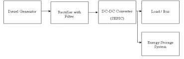
In this paper hybrid power system is designed with two renewable energy sources like wind and solar are connected with conventional energy source. A stand-alone wind system with solar photovoltaic system [5] is the best hybrid combination of all renewable energy systems and is suitable for most of the applications, taking care of seasonal changes. There are three types of integration available in IPS. They are DC coupled, AC coupled and Hybrid coupled. In an AC coupled, sources are connected to the AC grid where synchronization is required. Synchronization makes integration little bit complex. In DC coupled, sources are connected to the DC grid where synchronization is not required. So DC coupled system is very simple. In the Hybrid coupled system both DC and AC grid is used, it makes system complex and costly. In this paper since telecom load is selected DC coupled integration is proposed. Block diagram of Solar wind Hybrid system is shown in Fig 2.
Figure 2. Block Diagram Of Solar Wind Hybrid Power System
[image:2.612.319.517.510.652.2]645 converted to DC by diode rectifiers (AC/DC). All DC source avail is controlled by DC- DC converters, which makes DC suitable for telecom
application. For DC-DC conversion SEPIC
converter is proposed. In a wind source and diesel source SEPIC converter acts as a buck converter. In a solar power plant SEPIC converter acts as a boost converter. Battery bank is charged through charge controller with SEPIC boost converter. Battery bank discharging is controlled by selector switch. Dump load is connected to the grid to act as a load when the energy production is excess than load and state of battery is fully charged. In this proposed system Dump load is auxiliary battery bank to utilize the sources effectively. All sources and dump load are connected to the grid through selector switch. All selector switches are controlled by EEMC. Energy efficient management controller plays major role in selecting source to grid. Hybrid system provides reliable and sufficient supply to the load.
2.2 Wind Power System
The wind turbine captures the winds kinetic energy in a rotor consisting of two or more blades mechanically coupled to an electrical generator. Permanent Magnet Synchronous Generator (PMSG) [6] or Induction Generator (IG) performs as an alternator to produce electrical power. In this paper PMSG is preferred for wind power plant because of its high efficiency and power coefficient, Secure and stable operation, no need of slip rings and power factor correction condensers [7]. Block diagram of Wind power system is shown in Fig.3.
[image:3.612.318.512.398.517.2]
Figure 3. Block diagram of Wind power system
Wind turbines are classified into two general types: Horizontal axis and Vertical axis. Since vertical axis wind mill do not take the
advantage of the higher wind speeds at higher
elevations above the ground, in this paper
horizontal axis wind turbine is proposed. The amount of power produced by a wind turbine is expressed as shown:
PT= 0.5CpρAV3 (1)
Where ρ is the air density
A is the cross sectional area of the turbine, V is the wind velocity
The co efficient of power (Cp) is a value
dependent on the ratio between the turbine rotor’s angular velocity (wT), radius of the blade (R) and
the wind speed (V). This ratio is known as the Tip
speed ratio (TSR), and is represented by ∂. TSR is
given by:
∂= wT. R/V (2)
From the relationship between TSR and Cp, it is
possible to devise a control strategy that ensures that the wind turbine operates around or at the peak point of the curve. Such strategies are commonly referred to as Maximum Power Point Tracking (MPPT) [7] techniques.
Where wind turbine characteristics are unknown, the controller algorithm brings the operating point towards by stepwise increases or decreases in the rotational speed of the wind turbine. This is known as the perturbation and observation method. Generally, MPPT in this case is achieved using intelligent control methods. The most commonly used techniques are based on Fuzzy Logic controllers [8]. Block diagram of fuzzy logic controller is shown in Fig 4.
Figure 4. Block diagram of Fuzzy Logic Controller
Fuzzy logic starts with and builds on a set of user-supplied human language rules. The fuzzy systems convert these rules to their mathematical equivalents. This simplifies the job of the system designer and the computer, and results in much more accurate representations of the way systems behave in the real world. Additional benefits of fuzzy logic include its simplicity and its flexibility. Fuzzy logic can handle problems with imprecise and incomplete data, and it can model nonlinear functions of arbitrary complexity.
[image:3.612.90.270.508.588.2]646 degrees all defined as {N,Z,P} where VN,N, LN,Z, LP,P and VP represent very negative, negative, low negative, zero, low positive, positive and very positive respectively.
The degree of truth of m are configured as 7 degrees, lies between {0,1}. In this paper Sugeno type of fuzzy is proposed with Min-Max method fuzzification and weighted average method of defuzzification. In this paper 21 rules of fuzzy are proposed in this system. Surface view of the fuzzy to show the utilization of rules is shown in Fig.5, it shows that utilization of minimum area leads to quick response. The control rules are listed in Table I.
Table I: The Control Rules for m
Figure 5. Surface View of FLC
2.3 Solar Power System
The solar modules (photovoltaic –PV- cell) generate DC electricity whenever sunlight falls in solar cells. Solar radiation sustains all form of life on earth. According to estimates, sun
radiates 1.74 x 10 17 W of power per hour to earth
the daily solar energy radiation varies from 4-7 kwh per m2 and there are 270-300 sunny days in a year. Single PV cell produces a rather small voltage that has less practical use. The real PV panel always uses many cells to generate a large voltage.
The following parameters were used in the calculation of the net current of a PV cell.
• Saturation current of the diode, Io, Net
current from the PV panel I, Light-generated current inside the cell IL, Series
resistance Rs, which is internal resistance of the PV panel, Shunt resistance Rsh, in parallel with the diode, Rsh ,is very large unless many PV modules are connected in a large system, Diode quality factor, n. In an ideal cell Rs is 0 and Rsh is infinite. The net current of the PV cells is the difference between
the output currentfrom the PV cells and the diode
current is given by.
I=IL-Io[e(q(V+IRs)/nkT)-1] (3)
Where V is the voltage across the PV cell,
k is the Boltzmann’s constant (1.381 x 10 _23 J/K),
T is the junction temperature in Kelvin, q is the electron charge (1.602 x 10 _19 C), n is the diode ideality factor (1.62). Block diagram of PV power system is shown in Fig.6
[image:4.612.107.289.270.522.2]Figure 6. Block Diagram Of PV Power System
Figure 7. Block Diagram Of Fuzzy MPPT
647 using artificial intelligent controller like fuzzy logic controller [12] [13]. In this paper fuzzy logic controller is proposed for effective MPPT.
In this method of MPPT change in voltage and change in power is taken as input like incremental conductance method. Fuzzy logic controller of MPPT produces duty ratio as output. Pulses based on this duty ratio controls the switch in SEPIC. Inputs of the Fuzzy logic controller follow equations (4) and (5).
∆p=pi-pi-1 (4)
∆v=vi-vi-1 (5)
Block diagram of the fuzzy logic MPPT is shown in Fig.7. Mamdani type of fuzzy is proposed in this
paper. Inputs of fuzzy are represented as ∆p and ∆v.
A degree of truth for inputs are7 and for output is 9. Membership functions of inputs are {NB, NM, NS, Z, PS, PM, PB} named as Negative Big, Negative Medium, Negative Small, Zero, Positive Small, Positive Medium and Positive Big. Membership functions of output are {NVB, NB, NM, NS, Z, PS, PM, PB, PVB} it is similar to the inputs except Negative Very Big and Positive Very Big. Fig. 8 shows the membership functions of inputs and output.
Figure 8. Membership functions of inputs E and EC
Table 2: Control Rule for Solar MPPT
Surface view of FLC is shown in Fig. 9. Centroid method of defuzzification is proposed with 49 rules. Table 2 shows the rules of fuzzy logic controller.
[image:5.612.330.519.74.213.2]
Figure 9. Surface View Of Fuzzy Logic controller
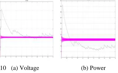
Fine tuned Fuzzy controller produces better duty ratio compared to conventional controllers. It results better voltage control in SEPIC and produces controlled power. Figure 10a & 10.b shows the comparison of voltage and power of SEPIC using Incremental conductance algorithm and Fuzzy logic controller.
[image:5.612.315.505.327.445.2]
10 (a) Voltage (b) Power
Figure 10. Comparison of SEPIC output voltage & power
using INC MPPT and FLC MPPT
2.4 Battery Energy Storage System
Storage of Energy produced by renewable energy based power system is very essential to provide a constant power to the load. The lead-acid battery is proposed in this paper for energy storage. It has two modes of operation charging and discharging modes. When the current to the battery is positive, the battery is in the charging mode. When the current to the battery is negative, the battery is in the discharging mode. The following parameters were used for modeling the battery [14]. SOC varies linearly with Vocb (open-circuit battery voltage).
648 As the terminal voltage of the battery is given by
Vbat=V1+IbatR1 (6)
Here R1 is the equivalent resistance of the battery. V1 and R1 both depend on the mode of battery operation and have different equations. Battery current; Ibat is positive when battery is in charge (ch) mode and negative when in discharge (dch)
mode. In charging mode, R1 and V1 are written as
R1=Rch=(0.758+ ) (7)
V1=Vch=[2+0.148SOC(t)]ns (8)
when the battery is charging.
In discharging mode R1 and V1 are written as,
R1=Rdch=(0.19+ ) (9)
V1=Vdch=[1.926+0.124SOC(t)]ns (10)
2.5 SEPIC Converter
The single-ended primary-inductance
converter (SEPIC) is a DC/DC-converter topology that provides a positive regulated output voltage from an input voltage that varies from above to below the output voltage [16]. This type of converter is the optimum converter for renewable energy sources since source voltage fluctuates above and below the output voltage. Unlike Cuk converter, it produces output as in the same polarity of input.
Assuming 100% efficiency, the duty cycle, D, for a SEPIC converter operating in DCM is given by (10)
D= (VOUT +VFWD)/(VIN+ VOUT +VFWD) (11)
Where VFWD is the forward voltage drop of the
diode.
Since the average voltage across C1 is VIN, the
output voltage
(VO) = VS1 - VIN (12)
SEPIC converters can acts as buck or boost converter. In a solar power plant and battery charging controller it acts as a boost converter. Condition to act as a boost converter is stated in (13)
Vs1>VIN (13)
In a wind and Diesel power plant it works in buck mode. Condition to operate in buck mode is stated in (14)
Vs1<VIN (14)
If VS1 is less than double VIN, then the output
voltage will be less than the input voltage. If VS1 is
greater than double VIN, then the output voltage will
be greater than the input voltage.
Switching loss of power device (MOSFET) in a SEPIC converter is given in (15)
PDSWITCHING = (CRSS x VIN² x fSW x ILOAD) / IGATE (15)
In the proposed project, less switching frequency is selected for switching the power device. It reduces the switching loss.
2.6 Diesel Generator
[image:6.612.325.510.304.364.2]In this paper diesel run generator is used as a standby power system. It is switched ON only when all the sources are individually or in combined conditions are not able to meet the load demand. In this condition controller activate the selector switch automatically. Now the load demand is met by DG and also battery charging continuously up to SOC of >95 %. This process is withdrawn if the main source is ready to supply to the load. Output of DG is AC, it is converted to DC through diode rectifier [17]. Fig.11 shows the simulation model of DG system
Figure 11. Block Diagram of Diesel Generator Power Source
2.7 Dump load
In renewable power sources like wind excess power is produced during high wind velocity (over generation). Nowadays this power is dissipated in a dump load. Generally resistor acts as a dump load. The excess power is wasted in existing renewable power plant. Occasionally a case may happens that load is very low, power generation is high and battery bank is also in a full charge state. In that situation power source is cut off. So the power generated is not utilized. In this paper Auxiliary Energy Storage System (AESS) is proposed as a dump load. It gives solution to store the excess energy produced by the power plant. With the help of AESS capacity of energy storage system is raised and usage of diesel generator can be minimized.
2.8 Load
The proposed system is capable of handling DC load as well as AC load. The DC load directly receives power from DC bus.
649 Output of inverter is filtered by LC filter and pure sine wave is given to the load. Three phase voltage from filter is shown in Fig.12
Figure 12. Three phase voltage from filter
3 FLC BASED EFFICIENT ENERGY MANAGEMENT CONTROLLER
FLC based Efficient Energy Management Controller (EEMC) monitors the status of load, power generated by wind source and PV system, SOC of the battery and Dump load battery [18] [19]. It receives all sources existing power and load power. Depending on the load and available power generated by source, it selects individual source or combination of sources supply to the grid. It continuously monitors the SOC of battery and activates the charge controller when the battery does not supply the load and SOC is less than SOCm. Battery and dump load battery discharging is limited to SOC minimum of 20%. Always battery is in the state to supply load.
In this paper the proposed FLC based Energy Management Controller handles the non conventional energy sources effectively and extends the life time of Battery bank. When the load is low or at initial stages the battery bank supplies load. EEMC produces signal and actuate discharging controller of the battery bank. The charging controller of battery bank is activated depends on the load demand, available resources and battery SOC. In case of high wind speed greater than wind mill rating then it is turned off.
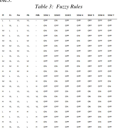
Fuzzy logic controller analyses the individual source power and load demand then controls the selector switch individually. In this paper Mamdani type of fuzzy is proposed with Min-Max method of fuzzification and centroid method of defuzzification. It has 5 inputs named as Pl, Ps,Pw,Pb and Pdb. It has 7 outputs such as SSW1, SSW2, SSW3, SSW4, SSW5, SSW6 and SSW7. All input has 4 triangular membership functions such as Very Low, Low, Medium and High {VL, L, M and H} and it is shown in Fig. 13.Maximum possible combination of sources under various loads is formed as rules.
Figure 13. Membership functions of input variable
[image:7.612.321.515.193.408.2]22 rules are proposed in this paper are shown in table3.
Table 3: Fuzzy Rules
Then during load variation selection of power source to bus by EEMC is discussed below with various conditions.
Case 1
It is the state when any one source is sufficient to run the load. Consider if solar alone is sufficient to run the load solar selector switch (SSW2) is activated and remaining selector switches are turned off. Battery charging controller (SSW3) is activated.
The equation (16) states the condition of case 1 is PS>=PL +Battery charging, if PBat >20% of SOC (16) Fuzzy rule to satisfy this condition is
“If (Pl is L) and (Ps is M) and (Pw is VL) and (Pb is M) then (SSW1 is off) and (SSW2 is on) and (SSW3 is on) and (SSW4 is off) and (SSW5 is off) and (SSW6 is off) and (SSW7is off)”
Case 2
It is the state when both renewable sources are sufficient to run the load. Solar and wind selector switch (S1, S2) is activated and remaining selector switches are turned off. Battery charging controller is activated.
650 Fuzzy rule to satisfy this condition is
“If (Pl is M) and (Ps is M) and (Pw is M) and (Pb is M) then (SSW1 is on) and (SSW2 is on) and (SSW3 is on) and (SSW4 is off) and (SSW5 is off)
and (SSW6 is off) and (SSW7is off)”
Case 3
It is the state when both sources are not sufficient (lesser than minimum set power) to run the load and battery alone is sufficient to run the load. Consider if battery alone is sufficient to run the load, battery selector switch (S4) is activated and remaining selector switches are turned off.
The equation (20) states the condition of case 3 is
PB>=PL (18) (20)
Fuzzy rule to satisfy this condition is
“If (Pl is L) and (Ps is VL) and (Pw is VL) and (Pb is M) then (SSW1 is off) and (SSW2 is off) and (SSW3 is off) and (SSW4 is on) and (SSW5 is off) and (SSW6 is off) and (SSW7is off)”
Case 4
It is the state when any one of the renewable source and battery are sufficient to run the load. Consider solar and battery are sufficient to meet the load. Solar and battery selector switch (S2, S4) are activated and remaining selector switches are turned off.
The equation (19 ) states the condition of case 4 is PB>=PL or Pw +PB>=PL (19)
Fuzzy rule to satisfy this condition is
“If (Pl is M) and (Ps is L) and (Pw is VL) and (Pb is M) then (SSW1 is off) and (SSW2 is on) and (SSW3 is off) and (SSW4 is on) and (SSW5 is off) and (SSW6 is off) and (SSW7is off)”
Case 5
It is the state when all the renewable sources and battery are not sufficient (lesser than minimum set power) to run the load, Dump load battery can meet the load. Dump load discharging selector switch (S7) is activated and remaining selector switches are turned off.
The equation (20) states the condition of case 5 is
PS +PB +PW<<PL &PDB >=PL (20)
Fuzzy rule to satisfy this condition is
“If (Pl is L) and (Ps is VL) and (Pw is VL) and (Pb is VL) then (SSW1 is off) and (SSW2 is off) and (SSW3 is off) and (SSW4 is off) and (SSW5 is off) and (SSW6 is off) and (SSW7is on)”
Case 6
It is the state when battery, Dump load battery and both renewable sources are not sufficient (lesser than minimum set power) to run the load, Diesel generator selector switch (S5) is activated and remaining selector switches are turned off. Battery charging controller is activated.
The equation (21) and (22) states the condition of case 6 is
PS +PB +PW + PDB <<PL (21)
PD >=PL +Battery charging, (22)
if PBat < 20% of SOC
Fuzzy rule to satisfy this condition is
“If (Pl is L) and (Ps is VL) and (Pw is VL) and (Pb is VL) then (SSW1 is off) and (SSW2 is off) and (SSW3 is on) and (SSW4 is off) and (SSW5 is on) and (SSW6 is off) and (SSW7is off)”
Case 7
It is the state when both the renewable sources power is excess than the load and battery is in fully charged state (SOC > 95%). So the excess power is stored in dump load battery. Dump load charging selector switch (S5), solar selector S3 and wind selector S1 are activated.
The equation (23) states the condition of case 7 is PS +PW >>PL
PS +PW >=PL +Pdb Charging if, PBat >95% of SOC (23) Fuzzy rule to satisfy this condition is
“If (Pl is L) and (Ps is H) and (Pw is H) and (Pb is H) then (SSW1 is on) and (SSW2 is on) and (SSW3 is off) and (SSW4 is off) and (SSW5 is off) and (SSW6 is on) and (SSW7is off)”
Similar to above said conditions fuzzy rule is set for other possible conditions.
4. SIMULATION RESULTS AND DISCUSSION
Simulation model of IPS with energy
management controller is developed using
MATLAB/ Simulink R2011b. Rating of the IPS is given below
Wind power plant : 1.5 kW, Solar power plant : 1.5 kW Battery : 3 kW Diesel Generator : 7kW Load (DC) : 1kW, -48 V
Load (AC) : 1kW, 440 V, 50Hz, 3 Phase Since telecom tower equipments works in -48V DC the proposed system is designed with the 48V DC bus. Also three phase AC is provided for other usage like light loads , Air Conditioner, & Cooling fan etc., used in telecom station.
Simulation results of few cases, explained in III are shown in Fig: 14- fig 20.
Case 1: Fig 15 shows the status of single source
651
Figure 14 Simulation result of the HPS when solar power alone supplies load
Case 2: Fig 15 shows the status of hybrid sources supplies load.
Figure 15. Simulation result of the IPS when solar and
wind supplies load
Case 3: Fig 16 shows the status of solar and battery supplies
[image:9.612.299.522.75.283.2]load
Figure 16 Simulation result of the HPS when solar and battery supplies load
Case 5: Fig 17 shows the status of Dump load battery alone supplies load
[image:9.612.314.525.345.491.2]
Figure 17 .Simulation result of the HPS when dump load
battery alone supplies load
Case 3: Fig 18 shows the status of battery alone supplies load
Figure 18 Simulation result of the IPS when battery alone
[image:9.612.92.285.358.569.2] [image:9.612.316.514.544.693.2]652 Case 6: Fig.19 shows the status of diesel generator supplies load
Figure 19 Simulation result of the HPS when diesel
generator alone supplies load
Case 7
The Fig. 20 shows the status of solar source supplies load and dump load battery.
Figure 20. Simulation result of the power plant when
solar power supplies load and dump load battery
5. CONCLUSION
The wind and solar hybrid power system is simulated using MATLAB. Fuzzy Logic MPPT Control is applied for wind and solar sources make the system efficient. Hybrid power system supplies AC and DC load so it is suitable for all applications like remote areas, villages and hill stations. Fuzzy
logic based Effective Energy Management
Controller controls hybrid power system to provide uninterrupted power, minimizing usage of diesel, effective utilization of sources and improves life time of battery. Since the usage of diesel generator is minimized emission of harmful gases from it is minimized. So it is a pollution free green energy system applicable to any location and any country.
This proposed system is optimally suitable for Telecommunication application where constant voltage and continuous power is required.
REFERENCES:
[1] Joanne Hui, Alireza Bakhshai &Praveen
K.Jain,“A Integrated Wind-Solar
EnergySystem: A New Rectifier Stag
Topology”, IEEE, 2010, pp. 155-161.
[2] I.A. Adejumobi, S.G. Oyagbinrin, F. G. Akinboro, & M.B. Olajide, “Integrated Solar
And Wind Power: An Essential For
Information Communication Technology
Infrastructure and People In Rural
Communities”, IJRRAS Vol 9, 2011, pp- 130-138.
[3] Juergen Biela, Uwe Badstuebner and Johann W. Kolar, “Design of a 5-kW, 1-U, 10- kW/dm3 Resonant DC–DC Converterfor
Telecom Applications” IEEE,vol-24,
2009,pp.1701-1710.
[4] Stephan S.Smith and M.Tariq Iqbal , “ Design and Control of a Hybrid Energy
System for Remote Telecommunications
Facility”, IEEE NECEC, 2008.
[5] Li Wang, Tsung-Jen Lin, “Stability and Performance of an Autonomous Integrated Wind-PV-Battery System”, The 14th Inter Conf on Intelligent System Applications to Power Systems, ISAP 2007, pp. 221-226.
[6] Alejandro Rolan', Alvaro Luna, Gerardo
Vazquez, Daniel Aguilar and Gustavo
Azevedo, “Modeling of a Variable Speed Wind Turbine with a Permanent Magnet
Synchronous Generator” IEEE
International Symposium on Industrial
Electronics, 2009, pp. 734-739.
[7] Neammanee B., Krajangpan K.,
Sirisumrannukul S. and Chatrattana S., “Maximum peak power tracking- based control algorithms with stall regulation for
optimal wind energy capture,” IEEE
Transactions in Energy Conversion, pp. 1424–1430, 2007.
[8]. Galdi V., Piccolo A. and Siano P., “Designing an adaptive fuzzy controller for Maximum wind energy extraction,” IEEE Transactions on Energy Conversion, vol. 2, pp. 559–569, 2008.
[9]. Ishaque, K., Z. Salam, H. Taheri and
Syafaruddin,J.Simpat, “Modeling and
653 during partial shading based on a two- diode model”. pp 1613-1626, 2011
[10] Safari, A. and S. Mekhilef,
“Incremental conductance MPPT method for PV systems”,IEEE Xplore Press,pp 000345-000347, May 8- 2011
[11] Safari, A. and S. Mekhilef , “Simulation
and hardware implementation of
incremental conductance MPPT with
direct control method using Cuk
converter”, IEEE Trans.,pp 1154-
1161,2011
[12] Nabulsi, A.A. and R. Dhaouadi, “Efficiency optimization of a DSP-Based standalone PV system using fuzzy logic and Dual-MPPT control”, IEEE Trans. Indus. Inform., pp 573-584, 2012
[13] Jamri, M.S. and T.C. Wei, “ Modeling and control of a photovoltaic energy system using the state-space averaging technique”,Am. J. Applied Sci., pp 682-691, 2010
[14] M.Kalantar, S.M. Mousavi G,
“Dynamicbehavior of a stand-alone integrated power generation system of wind turbine, microturbine, solar array and battery storage”, Applied Energy, vol 87, 2010, pp. 3051–3064 [15] J.-M. Kwon, W.-Y. Choi, J.-J. Lee E.H.Kim
and B.-H. Kwon, “Continuous-conduction-mode SEPIC converter with low reverse-recovery loss for power factor correction”, IEE Proc.-Electr. Power Appl., Vol. 153, 2006, pp-673-681.
[16] In-Dong Kim, Jin-Young Kim, Eui-Cheol Nho and Heung-Geun Kim, “Analysis and Design of a Soft-Switched PWM SEPIC DC-DC Converter”, Journal of Power Electronics, Vol. 10, 2010, pp. 461-467
[17] Kamal E., Koutb M., Sobaih A. and Kaddah S, “Maximum power control of integrated wind-diesel-storage system,” Hindawi Publishing Corporation Advances in Fuzzy Systems (Article ID 963710), 2008.
[18] Caisheng Wang, M. Hashem Nehrir, “Power
Management of a Stand-Alone Wind/
Photovoltaic/ Fuel Cell Energy System”, IEEE Transactions On Energy Conversion, VOL. 23, 2008, pp. 957-967.
[19] E.F.F.Riberio,A.J.Marques Cardoso and
C.Boccaletti, “ Uninterruptible Energy
Production in Standalone Power Systems for
Telecommunications”, International