GENERATION OF A NEW HYBRID SUBCARRIER
MULTIPLEXING–SAC-OCDMA SYSTEM BASED ON FSO
1,*HUSSEIN SAAD MOHAMMED, 2,*S. A. ALJUNID, 3,*HILAL A. FADHIL, 4,*THANAA
HUSSEIN ABD, 5,*RASHID A. FAYADH, 6,*A. K RAHMAN
*
School of Computer and Communication Engineering, University Malaysia Perlis, Malaysia E-mail: [email protected], [email protected], [email protected],
4
[email protected], [email protected], [email protected]
ABSTRACT
This paper proposes hybrid Subcarrier Multiplying-Spectral Amplitude Coding-Optical Code Division Multiple Access system (SCM-SAC-OCDMA) based on the Free Space Optic (FSO) using Multi Diagonal (MD) code is. The proposed hybrid system is used to evaluate the contribution of different haze conditions of Malaysia as a tropical weather country as well as evaluating the effects of different noise types such as shot noise, thermal noise and Inter-Modulation distortion. This system has been evaluated numerically and by simulation analysis. The results of the simulation analysis that the proposed system can transmit 1 Gb/s for 2.5 km for heavy haze under the transmission power of 6dBm at BER 10-10.
Keywords: SubcarrierMultiplexing (SCM), SAC-OCDMA, Multi Diagonal (MD) code, Radio Frequency
(RF), specific haze attenuation (αspec).
1. INTRODUCTION
The Free Space Optic (FSO) has provided a better alternative for wireless communication systems to transfer high data rate (full-duplex transmit and received data) simultaneously. FSO can be exploited instead of fiber optical due to it is several advantages such as using the atmosphere as a media to transfer signals, easier installation and being cheaper than Radio Frequency (RF) high secure system. However, the RF that is carried over Fiber optical (RoF) links the central offices (CO) and the radio access points (RAPs).Thus, this system is proposed to transfer high data rate as in [1].
The Optical Code Multiple Access (OCDMA) is part of the wireless communication system and modulated with RF to offer high bandwidth, increase users and decrease multi access interference (MAI) [2]. However, the hybrid SCM/SAC-OCDMA system combines two schemes in such a way that the resulting hybrid system is robust against the Multi Access Interference (MAI) and increases the data rate [3]. Consequently, the hybrid system based on the Multi-Diagonal (MD) code enhances the channel data rate as in [4].The RF over FSO link uses light source such as laser to propagate through the atmosphere. However, the
[image:1.612.315.524.529.667.2]advantages of FSO are unlimited bandwidth, free license compared with the deployment of microwave link, and immunity to electromagnet interference [5]. Moreover, FSO links can be stabled at less time and lower cost compared with fiber optic cable laying. However, FSO has one basic disadvantage and that is its being affected by weather conditions [6]. Figure 1 shows for outdoor environment the (FSO) transmission link using Line-of-Sight (LoS) mechanism which creates links between transmitter and receiver.
In this paper, we propose a new generation of hybrid Subcarrier multiplexing (SCM) SAC-OCDMA system based on FSO utilizing Multi Diagonal (MD) code to improve and overcome the attenuation of haze in the system performance according to tropical weather condition mainly for long range link of Malaysia [7,8]. In recent years, many papers have been published about FSO such as [9, 10, 11]. However, the researchers take the advantage of OCDMA and fulfill its application in FSO in different ways. Furthermore, we investigate the performance of hybrid system numerically and by using optical simulator software “Optsystem” ver.7 taking into the account the effect of inter modulation distortion noise, the shot noise and thermal noise. The remainder of paper is organized as follows. Section 2 presents the System Design. Section 3 devoted for the haze specific attenuation. Section 4 present the mathematical model of hybrid SCM-SAC-OCDMA system based on FSO. In section 5 the Numerical and Simulation Analysis are presented. Finally, conclusions are given in Section 6.
2. SYSTEM DESIGN
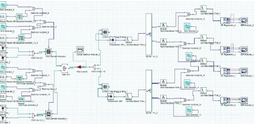
[image:2.612.314.522.72.238.2]Figure 2 shows the proposed SCM-SAC-OCDMA network which is designed based on MD code. In the transmitter side, external optical modulator (EOM) is utilized to merge data with independent unipolar digital signal which is optically modulated onto the code sequence [4]. The EOM such as Mach–Zehnder modulator is utilized to combine the RF signal with the code sequences and with the transmitter on FSO link [10]. While at the receiver side, an optical Splitter is used to separate the different modulated code sequences. The MD code sequences are filtered by using Fiber Bragg Grating (FBG) filters and then, transferred to photo-detector (PD) at the receiver [12]. Consequently, the SCM signals that are combined with each MD code sequence are split by an electrical splitter and band pass filter (BPF) to filter and reject unwanted signals.
Figure 2: Performance of SCM-SAC-OCDMA based FSO.
3. SPECIFIC ATTENUATION OF
HAZE(ΑSPEC)
The effect of weather on FSO during the light propagation at atmosphere will reduce the link availability. The attenuation of haze for Malaysia weather is investigated as in [7,8,13]. However, the haze causes scattering and absorption in laser light and is determined by the following expression as [14].
αspec=10/log10(α(λ))(dB/km), (1) To a given wavelength λ (in nanometers), the attenuation coefficient is approximated by [14]:
α(λ)=3.912/V(λ/550)-q, (2)
αspec is Attenuation of haze (dB/km), λ Wavelength (nm), V Visibility (km), and q is a coefficient dependent on the size distribution of the scattering particles and exploited by Kruse models reported in [13,14] and implemented in our simulation analysis.
The kruse model defined the q factor as:
4. MATHEMATICAL MODEL OF HYBRID
SCM-SAC-OCDMA SYSTEM BASED ON FSO
thermal noise
( )
Ith2 , shot noise( )
Ish2 ,Inter-Modulation Distortion
( )
I2IMD in the photo-detectoras well as the contribution the haze attenuation (α
spec). The SNR of an electrical signal is defined as the average signal power to noise power
[ ]
2 2σ
I
SNR= . Due to the zero cross correlation
property of MD code, there is no overlapping in spectra of different users. For that reason the effect of incoherent intensity noise has been ignored.
The variation of photo-detector as a result of the detection of an ideally unpolarized thermal light, which is generated by spontaneous emission, can be expressed as:
. spec 2 2 2 2 α
σ =Ish+Ith+IIMD+
Let CK(i) denote the ith element of the Kth MD code sequences, and according to the properties of MD code, the direct detection technique can be written as:
∑
= = = N i l K Else l K For W i C i C1 0, .
, ,
) ( )
( (3)
The following assumptions are made [17,18]: • Each light source is ideally unpolarized and its
spectrum is flat over the bandwidth [vo-∆v/2, vo+∆v/2] where vo is the central optical frequency and ∆v is the optical source bandwidth expressed in Hertz.
• Each power spectral component has an identical spectral width.
• Each user has equal power at the receiver. • Each bit stream from each user is synchronized.
The above assumptions are important for mathematical straightforwardness. Devoid of these assumptions, it is difficult to analyze the system; for example, if the power for each spectral component is not identical and each user has a different power at the receiver.
The power spectral density (PSD) of the received optical signals can be written as [19]:
) ( ) ( ) ( 1 1 i rect i c d v P v r K K N i K K sr
∑
∑
= = ∆= (4)
Where Psr is the effective power of a broadband source at the receiver, K is the active users , N is the MD code length, and dKis the
modulation data of nth subcarrier channel on the Kth optical codeword, which can be expressed as[15]:
∑
= = Nc n n K n K nk t u tm wt
d
1
,
, () cos( )
)
( (5)
) (
, t
unK is the normalized digital signal at the nth
subcarrier channel of the Kth codeword. wntis the
angular subcarrier frequency, mn,K is the
modulation index of the nth subcarrier of the Kth users. Where is Ncis the number of the subcarrier
channel on each codeword. [15,21] [22] assume an identical modulation index for all subcarrier channels as: , 1 0 , c K n N m ≤ ≤
The rect (i) function in Eq. (13) is given by
[
( 2 2)]
[ ( 2] [ ])
(i uv v0 2Nv N i uv v0 2Nv N i uNv
rect = − −∆ − + − − − −∆ − + = ∆
(6)
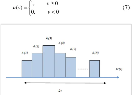
where u (v) is the unit step function expressed as:
< ≥ = 0 , 0 0 , 1 ) ( v v v
[image:3.612.312.526.228.381.2]u (7)
Figure 3: PSD Of The Received Signal G (v).
To compute the integral of G (v), let us first consider an example of the PSD (denoted by G’ (v) of the received superimposed signal), which is shown in Figure. 3, where A(i) is the amplitude of
the signal of the ith spectral slot with width of
N v
∆ .
The total power incident at the input of the photo-detector of Figure.3 is given by:
dv i rect i C i C t d v P dv v G K K N i l K K sr
∫
∑
∑
∫
∞ = = ∞ ∆ =0 1 1
0 ) ( ) ( ) ( ) ( )
( (8)
dv N v i C i C t d v P dv v G K K N i l K K sr
∫
∑
∑
∫
∞ = = ∞ ∆ ∆ =0 1 1
0 ) ( ) ( ) ( ) (
∑
∑
∫
= = ∞ ∆ ∆ = K K N i l K K sr i C i C t d N v v P dv v G 1 1 0 ) ( ) ( ) ( . ) (∑
∑
∫
= = ∞ = K K N i l K K sr i C i C t d N P dv v G 1 1 0 ) ( ) ( ) ( . ) (∑
∑
∫
= = ≠ ∞ + = K K N l K K K sr K sr t d N P t d N W P dv v G1 1,
0 ) ( ) ( . ) ( l sr d N W P dv v
G( ) .
0 =
∫
∞ (9)The photocurrent I can be found as:
∫
∞ ℜ = 0 ) ( dvv Gwhere,ℜ is the responsivity of the photo-detectors given by c hv e η = ℜ [17].
Here, η is the quantum efficiency, h is Planck’s constant, and vc is the central frequency of the original broad-band optical pulse.
Then Eq.(11) can be expressed as:
∑
∫
= ∞ ℜ = ℜ = Nc n n K n K n sr t w m t u N W P dv v G I 1 , , 0 ) cos( ) ( )( (11)
At the RF demodulator, the signal coherently mixed with a local oscillator 2cos(wnt)[10].
Therefore, Eq. (20) will be expressed as:
[
2cos( )]
, ) cos( ) ( 1 ,, tm wt wt
u N W P I n Nc n n K n K n sr
∑
= ℜ =[
]
∑
= + ℜ = Nc n n K n K n sr t w m t u N W P I 1 ,, () 1 cos(2 ),
While, the frequency double component will be filtered out by using LPF, as a result the modulator output is:
. )
( ,
,K nK
n sr m t u N W P
I =ℜ (12)
The noise power of shot noise can be written as [21]: , ) ( 2 0 2 ℜ
= eB
∫
∞GvdvIsh (13)
, . 2 ∆ ∆ ℜ = v W P N v eB sr , 2 N W P
eBℜ sr
= (14)
Note the probability of sending bit ‘’1’’ at any
time for each user is 2
1
, thus Eq. (14) becomes
. 2 N W P eB
Ish sr
ℜ
= (15)
Thermal noise is given as [21]
. 4 2 L n b th R B T K
I = (16)
WhereKb,Tn,B,andRL are the Boltzmann Constant,
Absolute receiver noise temperature, Noise– equivalent electrical bandwidth of the receiver and Receiver load resistor respectively. The intermediation distortion is given by [21,22].
. 64 32 1 , 2 1 , 1 , 1 6 , 2 2 2 + ℜ
=P m D D
IIMD sr nK (17)
Where D1,1,1is the three-tone third order
intermediation at,fi+ fK− fl,
}. ) 1 ]( ) 1 ( 1 [ 2 1 5 ) 3 {( 4 1 ) 1 ( 2 2 1 , 1 ,
1 c s c N N Ns
s c c N N N N
D = − + + − − − −− − +
1 , 2
D is the two-tone third order inter-modulation at2fi−fK,
}. ) 1 ]( ) 1 ( 1 [ 2 1 2 { 2 1 2 ,
1 Nc Nc Ns
D = − − − − −
Lastly from Eqs. (2), (12), (15), (16) and Eq. (17) we can compute the average Signal to Noise Ratio of the SCM-SAC-OCDMA system for the MD code as: q -21 111 6 K n, 2 2 sr L n b sr 2 K n, K n, sr (λλ/550 3.912/V + 64 D 32 D m P R B T 4K N W P eB (t)m u N W P SNR + ℜ + + ℜ ℜ = (18)
Using Gaussian approximation, the Bit Error Rate (BER) can be expressed as [12]:
. 8 2 1 =
=P erfc SNR
BER e (19)
4. NUMERICAL AND SIMULATION ANALYSIS
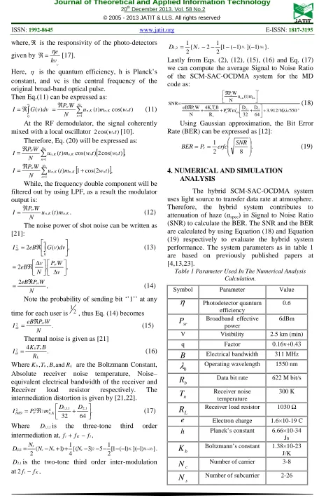
[image:4.612.74.530.39.749.2]The hybrid SCM-SAC-OCDMA system uses light source to transfer data rate at atmosphere. Therefore, the hybrid system contributes to attenuation of haze (αspec) in Signal to Noise Ratio (SNR) to calculate the BER. The SNR and the BER are calculated by using Equation (18) and Equation (19) respectively to evaluate the hybrid system performance. The system parameters as in table 1 are based on previously published papers at [4,13,23].
Table 1 Parameter Used In The Numerical Analysis Calculation.
Symbol Parameter Value
η
Photodetector quantumefficiency
0.6
sr
P
Broadband effectivepower
6dBm
V Visibility 2.5 km (min)
q Factor 0.16v+0.43
B
Electrical bandwidth 311 MHz0
λ
Operating wavelength 1550 nmb
R
Data bit rate 622 M bit/sn
T
Receiver noisetemperature
300 K
L
R
Receiver load resistor 1030 Ωe
Electron charge 1.6×10⁻¹⁹ Ch
Planck’s constant 6.66×10⁻³⁴Js
b
K
Boltzmann’s constant 1.38×10⁻²³J/K
c
N
Number of carrier 3-8s
Figure 4 illustrates The SCM-SAC-OCDMA system based on the MD code with subcarrier 0.61 GHz by using FSO link and compares the BER with the number of users. In addition, Figure 4 shows the effects of haze attenuation on the BER which has been increased through heavy haze and decreased at the clear haze. It is also observed that the BER is less than 10-9.
The visibility of light is reduced by the increased distance. Figure 5 shows the comparison between the BER and the visibility of light through atmosphere. It is found that the hybrid system using MD code with FSO technique can perform sufficiently well above 2.4 km with the BER of 10-9 at the heavy haze and the BER of 10-14 at the clear haze.
Active Users
2 3 4 5 6
B
E
R
10-25
10-24
10-23
10-22
10-21
10-20
10-19
10-18
10-17
10-16
10-15
10-14
10-13
10-12
10-11
10-10
10-9
10-8
10-7
[image:5.612.317.513.130.290.2]Clear Haze Light Haze Heavy Haze
Figure 4: Number Of Users Against BER.
Visibility(Km)
1.0 1.2 1.4 1.6 1.8 2.0 2.2 2.4
B
E
R
10-24
10-23
10-22
10-21
10-20
10-19
10-18
10-17
10-16
10-15
10-14
10-13
10-12
10-11
10-10
10-9
10-8
10-7
[image:5.612.95.283.315.458.2]Clear Light Heavy
Figure 5: Light visibility agents the BER.
The design of hybrid system is simulated by using “Optsystem” ver. 7. Figure 6 illustrates the scheme designed of the hybrid SCM-SAC-OCDMA system and also shows the implementations of hybrid system with 12 subcarriers channels which are used respectively. It can be observed that the hybrid system is using two subcarriers for each channel. The subcarrier frequencies are set at ≥2 (Niquest frequency) times the bit rate. However, due to using the atmosphere as transmission media, the unexpected weather conditions such as (haze) causes attenuation in the simulation analysis.
[image:5.612.92.529.490.702.2]Table 2 shows the information used in simulation for designing hybrid SCM-SAC-OCDMA based on FSO and (MD) code.
Table 2 the parameters used of design.
Figure 7 shows the impact of the data rate on the power receiver. In addition to that, the power receiver is increased at heavy haze by means of increasing data rate.
Bit Rate(Mb/s)
0 200 400 600 800 1000
P
o
w
e
r
R
e
c
e
iv
e
r
(d
B
m
)
-24.825 -24.820 -24.815 -24.810 -24.805 -24.800 -24.795
[image:6.612.90.271.166.365.2]Figure7: Data rate effect on the power receiver.
Figure 8 illustrates the different attenuations of haze such as (heavy, light and clear haze) versus the FSO distance. Figure 8 also shows that the performance of hybrid system has an effect on data rate. From the Figure, we can observe the BER compared with data rate. It is also observed that the transmitted high data rate increases the BER. Therefore, it can be concluded that, where the data rate for the hybrid system is increased to 1 Gb/s, the BER will be 10-9 at the heavy haze.
Bit Rate (Mb/s)
200 400 600 800 1000
B
E
R
10-30
10-29
10-28
10-27
10-26
10-25
10-24
10-23
10-22
10-21
10-20
10-19
10-18
10-17
10-16
10-15
10-14
10-13
10-12
10-11
10-10
10-9
10-8
10-7
Clear Haze Light Haze Heavy Haze
Figure 8: Data rate versus BER.
The beam divergence is one of the main advantages of FSO transmission as the narrowness of the transmitted laser beam can offer enhanced security. This narrow beam allows for security and can be achieved with well-designed optics efficient transmission with a major fraction of the transmitted power being collected by the receiver.
Figure 9 illustrates the impact of beam divergence on the hybrid system. From the Figure, we can observe the beam divergence compared with BER. It is also observed that the increase in the size of beam divergence leads to increase in BER.
Figure 10 and Figure 11respectively illustrate the eye diagrams for the hybrid SCM-SAC-OCDMA system by using 6 channels with 0.61 GHz for each subcarrier and transmitted through FSO link. The distance of transmission is 2.5 km. It is shown that the eye opening is decreased at the heavy haze and the eye opening for the BER is increased at the clear haze. Whereas the BER of the Figure10 and Figure 11 are 10-10 and 10-18 respectively when the system transmits 1 Gb/s with transmission power of 6 dBm.
Beam Divergence (m rad)
1 2 3 4
B
E
R
10-24 10-23 10-22 10-21 10-20 10-19 10-18 10-17 10-16 10-15 10-14 10-13 10-12 10-11 10-10 10-9 10-8 10-7 10-6 10-5
Clear Haze Light Haze Heavy Haze
Figure 9: Beam divergences against BER.
C-Band 1550nm
Spectral width 0.8nm
Power (dbm) 6 dBm
No. of user 6
No. of Subcarrier 12
Frequency 0.61GHz
FSO Length 2.5k m
Transmitter Aperture diameter 10 cm
Receiver Aperture diameter 32 cm
[image:6.612.316.509.588.711.2]Figure 10: Eye diagram taken at channel 1 distance 2.5 Km and heavy haze.
Figure 11: Eye diagram taken at channel 1 with distance 2.5 Km and clear haze.
5. CONCLUSION
In this work, we analyzed, in detail, the effect of different haze conditions on the SCM-SAC-OCDMA system for free-space optical communication applications. The analysis is based on MD code which is considered the recent code in OCDMA system. The hybrid system is evaluated for different distances with an input power level of 6 dBm. The coverage distance of the hybrid system is found to be 2.5 km with BER of 10-9 for 1 Gb/s under heavy haze condition. The system may further be analyzed for the possibility of providing more optical channels as well as for higher data rates.
REFRENCES:
[1] T. Spuesens, "A Hybrid Optical Code Division Multiple Access/Radio-over-Fiber System on a Passively-Split Optical Network," JUNE 2008. [2] R. K. Z. Sahbudin, et al., "Design and cost
performance of decoding technique for hybrid subcarrier spectral amplitude coding-optical code division multiple access system," Journal
of Computer Science, vol. 7, pp. 1525-1531, 2011.
[3] B. Huiszoon, et al., "Hybrid radio-over-fiber and OCDMA architecture for fiber to the personal area network," Journal of Lightwave Technology, vol. 27, pp. 1904-1911, 2009. [4] Thanaa Hussein Abd1*, S. A. A., Hilal A.
Fadhil1, Ibrahim Fadhil Radhi1, Ahmad R. B.1 and M. A. Rashid2, "Performance improvement of hybrid SCM SAC-OCDMA networks using multi-diagonal code," Academic vol. 7(11), pp. pp. 1262-1272, 23 March, 2012.
[5] R. K. Z. Sahbudin, et al., "Performance of SAC OCDMA-FSO communication systems," Optik, 2012.
[6] A. K. M. L. Singh, "Performance Evaluation of Free Space Optics (FSO) and Radio Frequency Communication System Due to Combined Effect of Fog and Snow," International Journal of Computer Applications® (IJCA), iRAFIT2012.
[7] N. A. M. Nor, et al., "Environmental effects on free space earth-to-satellite optical link based on measurement data in Malaysia," 2012, pp. 694-699.
[8] W. R. H. Wan Ruslan, et al., "TERRESTRIAL FREE SPACE OPTIC PROPAGATION ANALYSIS CONSIDERING MALAYSIA WEATHER CONDITION," Jurnal Teknologi (Sciences and Engineering), vol. 54, pp. 217-229, 2011.
[9]B. S. S. Naimullah, et al., "Analysis of the effect of haze on free space optical communication in the Malaysian environment," 2007, pp. 391-394.
[10]M. Noshad and M. Brandt-Pearce, "Expurgated PPM using symmetric balanced incomplete block designs," IEEE Communications Letters, vol. 16, pp. 968-971, 2012.
[11] H. A. Fadhil, et al., "New priority-based parameter optimization technique for free space optics under bad weather conditions," 2012, pp. 116-120.
[12] T. H. Abd, et al., "Modeling and simulation of multi diagonal code with zero cross correlation for SAC-OCDMA networks," 2011.
[13] A. S. M. S. a. a. F. D. M. Fatin Hamimi Hamat@Mustafa*, "Simulation of FSO Transmission at Petaling Jaya due to Attenuations Effect," ELEKTRIKA, vol. VOL. 12, NO. 1, pp. 30-34, 2010.
Optical Engineering, vol. 43, pp. 319-329, 2004.
[15]S. A. A. N. Ahmed1*, H. A. Fadil1, R. B. Ahmad1, M. A. Rashid2, "Performance improvement of SAC-OCDMA system using modified double weight (MDW) code for optical access network," Academic, vol. Vol. 7(7), pp. pp. 796-804, 23 February, 2012. [16] Palais J C (2005). Fiber optic communication, ”
fifth ed., Pearson/Prentice Hall.
[17] E. D. J. Smith, et al., "performance enhancement of spectral-amplitude-coding optical CDMA using pulse-position modulation," IEEE Transactions on Communications, vol. 46, pp. 1176-1185, 1998. [18] J. H. Wen, et al., "Optical spectral amplitude coding CDMA systems using perfect difference codes and interference estimation," IEE Proceedings: Optoelectronics, vol. 153, pp. 152-160, 2006.
[19] J.-F. H. Chao-Chin Yang, and Shin-Pin Tseng, "Optical CDMA Network Codecs Structured With M-Sequence Codes OverWaveguide-Grating Routers," IEEE PHOTONICS TECHNOLOGY LETTERS, vol. 16, NO. 2, pp. 641-643, FEBRUARY 2004.
[20] B. John Koshy, "Spread-spectrum techniques for fiber-fed microcellular networks," IEEE Transactions on Vehicular Technology, vol. 48, pp. 847-857, 1999.
[21] Hilal A F, Aljunid. S A, Ahmad. R B (2009) Performance of random diagonal code for OCDMA systems using new spectral direct detection technique. Optical Fiber. J. Technol., 15 283-289.
[22] B. J. Koshy and P. M. Shankar, "Efficient modeling and evaluation of fiber-fed microcellular networks in a land mobile channel using a GMSK modem scheme," IEEE Journal on Selected Areas in Communications, vol. 15, pp. 694-706, 1997.