Design and Analysis of Compact 108 Element Multimode Antenna
Array for Massive MIMO Base Station
Akshay Jain1, * and Sandeep K. Yadav2
Abstract—In this paper, we report the design and evaluation of a compact 108-element base station antenna array for massive multi-input multi-output (MIMO) system using a 3-port multimode antenna as a unit element. Of these three ports, port 1 and port 2 have orthogonally polarized broadside radiation pattern with measured peak gain of 6.5 dBi and impedance bandwidth of 254 MHz (2.268 GHz– 2.522 GHz) and 238 MHz (2.248 GHz–2.486 GHz), respectively, while port 3 has monopole-like radiation pattern having measured peak gain of 1.21 dBi and impedance bandwidth of 102 MHz (2.376 GHz– 2.478 GHz). Mutual coupling among all the ports is kept as less than −14 dB. Design of 108-element massive MIMO antenna array is evaluated as a base station antenna for multiuser urban street grid scenario in MIMO-OFDM downlink system, which is further modeled using Wireless World Initiative New Radio II (WINNER II) Channel models in MATLAB. Parameters like Singular value spread and Dirty Paper Coding (DPC) sum capacity was calculated and compared with i.i.d channel model. For 4 users case using same frequency and time resource, singular value spread and DPC sum capacity for presented antenna array converges to 7 dB and 11.6 bps/Hz at 10 dB SNR respectively.
1. INTRODUCTION
In today’s scenario of increasing automated applications, machine to machine communication and urge of the high-speed internet with very low latency requirements, load has increased on current communication technologies and infrastructure. Thus ongoing research in MIMO technologies have witnessed a quantum jump on data rates with improved quality of service. Massive MIMO is a new 5G technique which can serve multiple users simultaneously over same time-frequency resource to cater ever emerging need of high-speed and reliable wireless communication [1]. Compared to LTE, the base station in massive MIMO technology is equipped with a large number of antennas (hundreds to thousands), which helps to improve the conventional MIMO performance in terms of link reliability, spectral efficiency and transmits energy efficiency [2, 3]. The basic idea behind massive MIMO is that as the number of antennas in base station increases, it makes channel vectors among users and base station antenna pair-wise orthogonal under rich scattering propagation conditions [4]. Although a lot of research has gone into the baseband part of Massive MIMO technologies, very few papers have been about antenna technologies particularly to address the challenges faced while designing Massive MIMO antenna. Major challenges involved in large-MIMO antenna design include mitigating the huge real estate requirement in conventional designs and meeting the requirement of easy replacement of faulty antenna elements without disturbing the whole setup. Recent research efforts in this area therefore focus on multiport multimode antenna design for MIMO application which allows more than one antenna elements to be co-located, and it also supports multiple polarizations and pattern diversities [5], though in some such reports [6–8] multiport multimode antennas have either large size and complex fabrication process, or small impedance bandwidth. The 3-port multimode antenna presented in this paper is a simple three-layer stacked patch structure, having 3 co-located antenna elements with orthogonal polarization &
Received 5 November 2015, Accepted 13 January 2016, Scheduled 27 January 2016
* Corresponding author: Akshay Jain ([email protected]).
radiation patterns. It is packed in a cylindrical array to form a 108-element massive MIMO antenna having much smaller size than that of the conventional MIMO antenna. Design and analysis of the proposed multimode antenna and its compact 108-element antenna array for massive MIMO base station application are presented and discussed in subsequent sections.
2. ANTENNA DESIGN
2.1. Design of 3-Port Multimode Antenna
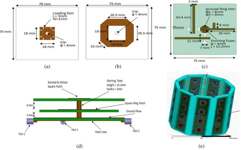
The three-port multimode antenna consists of a compact three-layer structure with aperture coupled stacked patch configuration having a dimension of 75 mm×75 mm×14.8 mm. It is designed using 3D EM simulation software FEKO & HFSS 13.0. As shown in Figure 1, it has a upper patch, a middle patch and a ground plane with slots for aperture coupling. It is fabricated on an FR4 substrate of dielectric constant 4.4 and thickness 1.6 mm. The separation between upper and middle layers is kept at 6 mm and between ground and the middle layer is 4 mm. The upper patch is a slot loaded square patch and radiates monopole-like radiation pattern. It is connected to port 3 through capacitive coupling using a copper tube of radius 2 mm and length 13.2 mm via an annular slot of inner radius 3 mm and outer radius 4 mm. The middle patch is a square ring patch generating two orthogonally polarized broadside radiation patterns. Two H-shaped slots on the ground plane, placed orthogonally to each other and parallel to the sides of square ring patch, are used to connect the middle patch to port 1 and port 2 through aperture coupling.
(a) (b) (c)
(d) (e)
Figure 1. Geometry of designed multimode three-port antenna. (a) Top patch, (b) middle patch, (c) feed & ground, (d) assembled CAD view of antenna, (e) 3D CAD view of 108-element antenna array.
2.2. Design of 108-Element Antenna Array
arranged in a 9-faced polyhedron ring, with 4 such rings stacked on top of one another with vertical displacement of 60 mm (λ/2), to design a compact 108-element antenna array. 3D CAD model of the antenna array is shown in Figure 1(e). The designed antenna array is thus compact in size with a height of 255 mm and radius of 150 mm. In comparison to that, a uniform linear array (ULA) of 108 elements with (λ/2) inter-element spacing will be of 6.24 m length, which is about 20 times the size of designed array.
3. MEASURED PARAMETERS
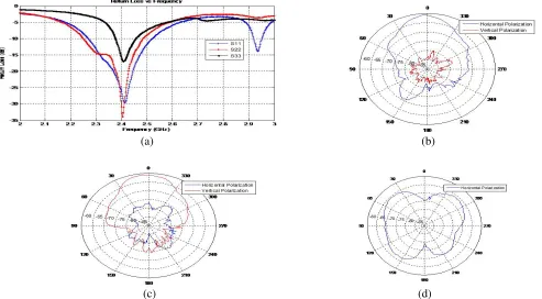
Based on this design, a prototype of the 3-port multimode antenna is fabricated and illustrated in Figures 2(a)–(b). Its measuredS-parameters are given in Figure 3(a). Ports 1 and 2 have the impedance bandwidths of 254 MHz (2.268 GHz–2.522 GHz) and 238 MHz (2.248 GHz–2.486 GHz), respectively while port 3 have the impedance bandwidth of 102 MHz (2.376 GHz–2.478 GHz).
(a) (b)
Figure 2. (a), (b) Fabricated antenna prototype top view & side view.
(a) (b)
(c) (d)
Measured co- and cross-pol. radiation patterns for ports 1 and 2 at 2.4 GHz are illustrated in Figure 3(b) and Figure 3(c), respectively. Port 1 has horizontally polarized broadside radiation pattern with measured peak gain of 6.5 dBi and cross-polarization level of 17.7 dB at 2.4 GHz. Similarly, Port 2 has vertically polarized broadside radiation pattern of peak gain 6.5 dBi and cross-polarization level of 13.23 dB.
Figure 3(d) shows the measured co-pol. radiation pattern of port 3, and it has measured peak gain of 1.21 dBi with conical radiation pattern.
4. CALCULATION & ANALYSIS OF MASSIVE MIMO PERFORMANCE PARAMETERS
4.1. Operating Scenario
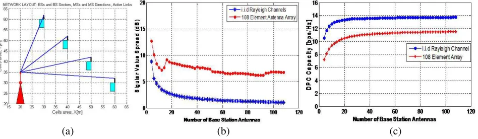
The designed base station antenna array is envisaged to be operative in a typical urban street grid scenario, serving simultaneously four users in MIMO-OFDM downlink system. As shown in Figure 4(a), all the mobile stations have LOS to the base station antenna and are far away from one another with 15 m inter-user spacing.
(a) (b) (c)
Figure 4. (a) Network layout with one base station antenna and four active links, (b) calculated singular value spread, (c) calculated average DPC sum rate capacity.
WINNER II channel models were used to estimate channel matrix (H), using the following network parameters as given in Table 1.
Table 1. Network parameters.
S. No Parameter Value
1 Number of antenna elements at Base station Array (A) 108
2 Number of Mobile Stations with vertically polarized single antenna (K) 4
3 OFDM sub carriers (N) 161
4 Center Frequency 2.4 GHz
5 Bandwidth 50 MHz
6 SNR 10 dB
7 Base station height 20 m
8 Mobile station height 1.5 m
4.2. Singular Value Spread
value spread of normalized propagation matrix [9], having the following normalization
hnormi,l =
AN N l=1
hrawi,l 2
hrawi,l (1)
where, hrawi,l , i= 1,2, . . . , K is the ith rows of estimated channel matrix hrawl , corresponding to each user, A the total number of antenna elements in base station array, N the total number of OFDM subcarriers, and hnormi,l the ith row of normalized channel matrix hnorml at subcarrier l, corresponding to user i.
Now the normalized propagation matrixHlat subcarrierlhas SVD (singular value decomposition) as
Hl =UlΣlVlH (2)
where,UlandVl are unitary matrices, andΣl= diag{σl,1, σl,2. . . σl,K}is aK×Adiagonal matrix and
contains singular values of the channel at subcarrierl. Here, K is the total number of links between BS & MS and Athe total number of column inHl.
Now, the singular value spread, also called condition number, is defined as the ratio of the largest to smallest singular values of the channel. It indicates the guaranteed minimum quality of service for all users.
κl= σσlmax lmin
(3)
κl = 1 (0 dB) implies the best situation that all the rows are pairwise orthogonal, while large value of singular value spread κl indicates that at least two users are close to parallel and hence difficult to separate.
The curves of variation of singular value spread versus a number of base station antennas in i.i.d Rayleigh channel and simulated channels with 108-element base station antenna are shown in Figure 4(b). For each subcarrier, several base station antennas were selected from random 20 antenna subsets of the designed antenna array, and median of singular value spread was taken over all subcarriers. As seen from Figure 4(b), there is a variation of 8 dB in the case of i.i.d Rayleigh channels, and its value converges to 1 dB as the number of antenna increases from 4 to 50. Similarly, for the designed 108-element antenna array, singular value spread converge to approx 7 dB with a variation of 6 dB as the number of antennas grows from 4 to 60.
4.3. DPC Channel Capacity
Capacity is the ultimate parameter to evaluate the communication performance in any channel. For a massive MIMO case where multiple co-channel users are to be served simultaneously, each user can be allocated different power fractions out of total available transmit power. This arrangement may result in different information rates. So, sum capacity of the complete channel can be calculated by maximizing the individual capacity of all users.
For narrow band multi-user MIMO downlink channel, sum rate capacity based on Dirty Paper Coding (DPC) [9–11] is expressed as
CDPC,l = max
Pl
log2det
I+ρK
M HHl PlHl
(4)
Here Pl is the diagonal matrix which allocates power to K user channels. Capacity is calculated by optimizing over total power constraint Ki=1Pl,i,i= 1,2, . . . , K, using sum power iterative water-filling algorithm. Here Hl is the normalized channel matrix at subcarrier l, and M is the number of columns in normalized channel matrix.
As the number of base station antennas grows to infinity, maximum interference-free sum rate capacity converges to
CIF=Klog2(1 +ρ) (5)
In our case, with four users,K = 4, andρ= 10 dB, calculated maximum sum rate capacity comes out to beCIF= 13.8 bps/Hz.
The curve of average DPC sum rate capacity versus number of base station antennas for i.i.d Rayleigh channels and the proposed 108-element antenna array is shown in Figure 4(c). As shown, the average capacity in i.i.d Rayleigh channel case has very little variation and converges to the asymptotic limit of 13.8 bps/Hz, as the number of antennas increases from 4 to 60. On the other hand, for redesigned 108-element antenna array, average DPC sum-rate capacity has large variations with number of base station antennas, and it converges to 11.6 bps/Hz when the number of antennas is above 60. This drop in average capacity coincides with larger singular value spreads.
5. CONCLUSION
A compact base station antenna array having 108 antenna elements is successfully designed, simulated and analyzed. The designed antenna uses a novel 3-port multimode square patch antenna as a base unit. The structure has a radius of 150 mm and height of 255 mm. Massive MIMO performance parameters like Singular Value Spread and Dirty Paper Coding Sum-Rate Capacity were calculated for 108-element base station antenna in LOS urban street grid scenario with 4 single antenna mobile stations and compared against standard i.i.d Rayleigh Channel. This base station antenna performs at 85% of asymptotic capacity and is able to resolve different user channels with 7 dB singular value spread. The 108-element base station antenna is compact and much smaller in size than conventional ULA and UCA. Furthermore, it is easy to install and has a modular design, allowing easy replacement of individual faulty antenna units without affecting its operations.
REFERENCES
1. Larsson, E. G., et al., “Massive MIMO for next generation wireless systems,” IEEE
Communications Magazine, Feb. 2014.
2. Marzetta, T. L., “Noncooperative cellular wireless with unlimited numbers of base station antennas,”IEEE Transactions on Wireless Communications, Vol. 9, No. 11, 3590–3600, Nov. 2010. 3. Rusek, F., D. Persson, B. K. Lau, E. G. Larsson, T. L. Marzetta, O. Edfors, and F. Tufvesson, “Scaling up MIMO: Opportunities and challenges with very large arrays,”IEEE Signal Processing
Magazine, Jan. 2013.
4. Ngo, H. Q., E. G. Larsson, and T. L. Marzetta, “Energy and spectral efficiency of very large multiuser MIMO systems,” IEEE Transactions on Communications, Vol. 61, No. 4, 1436–1449, 2013.
5. Antonino-Daviu, E., M. Cabedo-Fabrs, et al., “Design of a multimode MIMO antenna using the theory of characteristic modes,”Radioengineering, Vol. 18, No. 4, Dec. 2009.
6. Sarrazin, J., Y. Mah, S. Avrillon, and S. Toutain, “A new multimode antenna for MIMO systemsusing a mode frequency convergence concept,” IEEE Transactions on Antennas and
Propagation, Vol. 59, No. 12, Dec. 2011.
7. Rajo-Iglesias, E., O. Quevedo-Teruel, and M. Sanchez-Fernandez, “Compact multimode patch antennas for MIMO applications,” IEEE Antennas and Propagation Magazine, Vol. 50, No. 2, Apr. 2008.
8. Waldschmidt, C. and W. Wiesbeck, “Compact wide-band multimode antennas for MIMO and diversity,” IEEE Transactions on Antennas and Propagation, Vol. 52, No. 8, Aug. 2004.
9. Gao, X., O. Edfors, et al., “Massive MIMO performance evaluation based on measured propagation data,” IEEE Transactions on Wireless Communications, Mar. 2015.
10. Vishwanath, S., N. Jindal, and A. Goldsmith, “Duality, achievable rates, and sum rate capacity of Gaussian MIMO broadcast channels,”IEEE Transactions on Information Theory, Vol. 49, No. 10, 2658–2668, Oct. 2003.