253
Implementation of 64-Bit Radix-8 FFT by Decimation
in Frequency (DIF) Using Verilog
B. Anil Kumar1, K.Rujwala2, V.Satyaarjun3,P.Parvathiswara Rao4
Dept. of ECE 1,Dept. of ECE2, Dept. of ECE3, Dept. of ECE4,MRIET1, MRIET2, MRIET3, MRIET4 ( Email: [email protected] ,[email protected], [email protected],
Abstract-Always technical designers choice includes algorithms, flowcharts, programming etc and the end users requires given input and application output. Based upon this view this paper focus on the advancement of Fast Fourier Transform(FFT) by doing design and observing the performance analysis of 64 point FFT, using Radix 8 algorithm. The algorithm is developed by Decimation In Frequency(DIF) of FFT,using VHDL as design entity and synthesis ar performed in Xilinx. In this architecture the number of stages are reduced to 75%.
Index Terms-FFT, DIF, Verilog,,XILINX..
1. INTRODUCTION
A fast Fourier transform (FFT) is an efficient algorithm to compute the discrete Fourier transform (DFT) and its inverse. There are many distinct FFT algorithms involving a wide range of mathematics, from simple complex number arithmetic to group theory and number theory.
A DFT decomposes a sequence of values into components of different frequencies. This operation is useful in many fields (see discrete Fourier transform for properties and applications of the transform) but computing it directly from the definition is often too slow to be practical. An FFT is a way to compute the same result more quickly: computing a DFT of N points in the naive way, using the definition, takes O(N2) arithmetical operations, while an FFT can compute the same result in only O(N log N) operations. The difference in speed can be substantial, especially for long data sets where N may be in the thousands or millions—in practice, the computation time can be reduced by several orders of magnitude in such cases, and the improvement is roughly proportional to N / log(N). This huge improvement made many DFT based algorithms practical; FFTs are of great importance to a wide variety of applications, from digital signal processing and solving partial differential equations to algorithms for quick multiplication of large integers.
The most well known FFT algorithms depend upon the factorization of N, but there are FFTs with O(N log N) complexity for all N, even for prime N. Many FFT algorithms only depend on the fact that e¯ 2∏ i /N is anth primitive root of unity, and thus can be applied to analogous transforms over any finite field, such as number theoretic transforms. Since the inverse DFT is the same as the DFT, but with the opposite sign in the exponent and a 1/N factor, any FFT algorithm can easily be adapted for it.
2. LITERATURE SURVEY
J. W. Cooley and J. W. Tukey. An algorithm for the machine calculation of complex Fourier series. Mathematics of Computation, 1965. A fast algorithm for computing the Discrete Fourier Transform . (Re)discovered by Cooley & Tukey in 19651 and widely adopted thereafter has a long and fascinating history.Explained the design of pipelined structure from Radix-8 FFT with DIF algorithm using efficient butterfly structure. The different and dedicated structures for the 64 bit-width pipelined radix-8 DIF butterfly structure are implemented. The main goal of this paper is to minimize the number of real multipliers of the architectures. This is done by varying the structure of the complex multipliers and applying them into the butterflies. These structures are widely used in fast and low power multiplier architectures. In pipelined Radix-8 FFT structures have been developed with the help of Feed forward structures. Feed forward structure provides 26ns for performing 8-point FFT.
3. EQUATIONS
The main reason for going with Fast Fourier Transform is to reduce the complexity and make mathematical calculations easier compared to that of DFT.The formulae what we use in DFT fails for higher complex stages where the calculations become unperformable, So here in FFT we go for higher complex stages with reduced number of calculations and complexity. The main difference between the calculations performed in DFT and FFT is logarithm.
In this paper we are trying to implement the FFT using DIF with log base 8i.e.,Radix 8 structure implementing 64 bits of data.
254 General Equations
M-1
X(K)=∑x(n)WN--- (1) N=0
N/2-1 N-1
X(K)=∑x(n)Wnkn+∑x(n)Wnkn ---(2) n=0 n=N/2
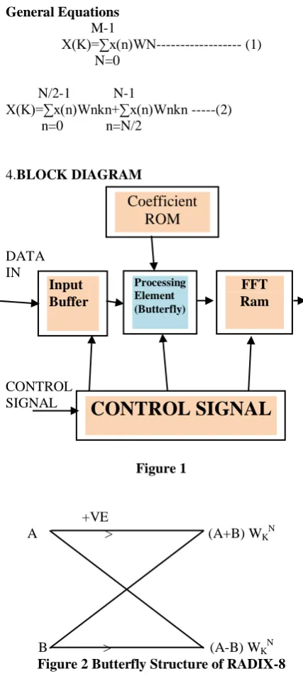
4.BLOCK DIAGRAM
DATA IN
[image:2.595.68.282.99.576.2]CONTROL SIGNAL
Figure 1
+VE
A > (A+B) WKN
[image:2.595.302.552.354.465.2]
B > (A-B) WKN Figure 2 Butterfly Structure of RADIX-8
In the radix 8 FFT first we align the data and it is given to the input buffer which controls the data and performs the distribution property which allows data to perform their operations in a sequence.The next block refers to the processing element i.e.,Radix 8 Butterfly structure,Where the number of stages reduced to 75%.The next and main block of the structure is control signal which performs data control and processing control.The next block COEF ROM allows the processing element t perform the calculations and store the result temporarily for future years.
DESCRIPTION
Compare to that of radix 2 and radix 4 here in this paper we perform radix 8 operations by using the twiddle factors. The radix 8 butterfly structure helps
us to carry out the complex calculations in the easier way.
In the butterfly structure of Radix 8 point FFT we have 2 stages.The number of stages are obtained by reducing the complexity using the FFT.The number of stages are obtained as follows below.
CALCULATIONS
To find the number of stages mathematically the equation is
n=logN8
N= number of samples n= number of stages
n=log864 n=2log88
so,number of stages(n)=2.
S.no Number of complex additions
Number of complex multiplication
1. DFT
N(N-1)=64(64-1) =4095
FFT N2=642=4096
2. DFT
NLog8N=64log864 =128
FFT
N/2Log8N=64/2log864 =64
From the above table we can conclude that ,In DFT for the higher stages the complexity increases where in FFT the complexity is reduced .
5. PROCESS OF DECIMATION
First step of decimation is splitting a sequence in a smaller sequences.A sequence of 64 Bit can be splitted in 8 sequences of 4 blocks.Here on the first stage carries out the butterfly operation by applying the twiddle factor.
In the second stage the output from the 64 Bit FFT is split into sequence of 8 equal parts.and the initial 32Bits are performed by addition and twiddle factor multiplication and then followed 32 Bits perform subtraction and multiplied with twiddle factor.
Twiddle factors :
=
For 64 points,the twiddle factor is represented as, N=64,
= =1
= =0.995-j0.098
= =0.980-j0.195
Coefficient ROM
Input Buffer
Processing Element (Butterfly)
FFT Ram
255
= =0.956-j0.290
= =0.923-j0.382
= =0.881-j0.471
= =0.831-j0.555
= =0.773-j0.634
= =0.707-j0.707
= =0.634-j0.773
= =0.555-j0.831
= =0.471-j0.881
= =0.382-j0.923
= =0.290-j0.956
= =0.195-j0.980
= =0.098-j0.995
= =-j
= =-0.098-j0.995
= =-0.915-j0.980
= =-0.290-j0.956
= =-0.382-j0.923
= =-0.471-j0.881
= =-0.555-j0.831
= =-0.634-j0.773
= =-0.707-j0.707
= =-0.773-j0.634
= =-0.831-j0.555
= =-0.881-j0.471
= =-0.923-j0.382
= =-0.956-j0.290
= =-0.980-j0.195
= =-0.995-j0.098
= =-1
= =-0.995+j0.098
= =-0.980+j0.195
= =-0.956+j0.290
= =-0.923+j0.382
= =-0.881+j0.471
= =-0.831+j0.555
= =-0.773+j0.634
= =-0.707+j0.707
= =-0.634+j0.773
= =-0.555+j0.831
= =-0.471+j0.881
= =-0.382+j0.923
= =-0.290+j0.956
= =-0.195+j0.980
= =-0.098+j0.995
= =j
= =0.098+j0.995
= =0.195+j0.980
= =0.290+j0.956
= =0.382+j0.923
= =0.471+j0.881
= =0.555+j0.831
= =0.634+j0.773
= =0.707+j0.707
= =0.773+j0.634
= =0.831+j0.555
= =0.881+j0.471
= =0.923+j0.382
= =0.956+j0.290
= =0.980+j0.195
= =0.995+j0.098
Inputs at stage1:-
x(n)=(1,1,1,1,1,1,1,1,2,2,2,2,0,0,0,0, 1,1,1,1,1,1,1,1,2,2,2,2,0,0,0,0,
1,1,1,1,1,1,1,1,2,2,2,2,0,0,0,0, 1,1,1,1,1,1,1,1,2,2,2,2,0,0,0,0 )
Outputs of stage :- X(K) =
(2,0,2,0,0.293+0.707i,0.707-
256
2,0.76+1.84i,1.414+1.414i,-1.84-0.76i,1.707- 0.707i,4014+2.76i,0.639-0.98i,4.88+3.24i,1.86-
2.76i,0.08-0.38i,1.087+0.213i,-0.327+1.627i,1.92+0.38i,1.414+1.414i,1.414i, -1.414+10414i,6,5.519+2.26i,-4.2414.22i,2.28+5.52i, 2,0.76+1.84i,1.414+1.414i,-1.84-0.76i,
2,0,2,0,0.293+0.707i,0.707- 0.293i,0.707+1.707i,1.707-0.707i,4014+2.76i,0.639-0.98i,4.88+3.24i,)
Block Diagram:
x[0] X[56]
x[1] X[57]
x[2] X[58] x[3] X[59]
x[4] X[60] x[5] X[61]
x[6] X[62]
x[7] X[63]
x[8] X[48]
x[9] X[49] x[10] X[50] x[11] X[51] x[12] X[52]
x[13] X[53]
x[14] X[54]
x[15] X[55] x[16] X[40]
x[17] X[41]
x[18] X[42]
x[19] X[43]
x[20] X[44] x[21] X[45] x[22] X[46] x[23] X[47] x[24] X[32] x[25] X[33] x[26] X[34] x[27] X[35]
x[28] X[36]
x[29] X[37]
x[30] X[38] x[31] X[39]
x[32] X[24]
x[33] X[25]
x[34] X[26]
x[35] X[27] x[36] X[28] x[37] X[29]
x[38] X[30]
x[39] X[31]
x[40] X[16] x[41] X[17]
x[42] X[18] x[43] X[19] x[44] X[20]
x[45] X[21]
x[46] X[22]
x[47] X[23] x[48] X[8]
x[49] X[9] x[50] X[10]
x[51] X[11]
x[52] X[12]
x[53] X[13]
x[54] X[14] x[55] X[15] x[56] X[0] x[57] X[1] x[58] X[2] x[59] X[3] x[60] X[4] x[61] X[6] x[62] X[7]
6. SOFTWARE SIMULATION AND RESULTS The proposed FFT block of signal length 64 is been simulated and synthesized using the Xilinx Design Suite 16.1. The RTL block thus obtained for the decimation in time domain radix -8 Fast Fourier transform algorithm is shown The RTL view of the butterfly structure obtained after the simulation of the 64-point FFT block, Decimation in time domain is shown next and also the internal architecture of the butterfly block is shown.
Figure3: RTL View Of A Butterfly Component Used In 64-Point FFT
64
-POINT
DFT
32-POINT
DFT
32-POINT
257 Figure 4: Internal Architecture of The Butterfly
Component
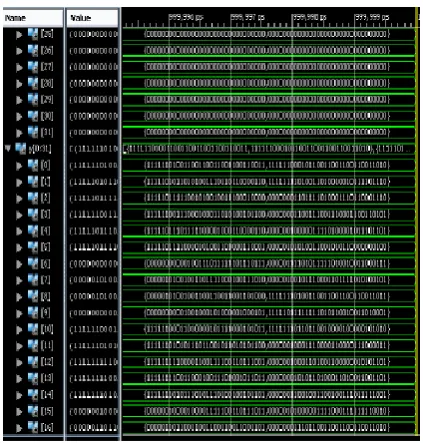
Figure5: Simulation results of the 64-point FFT
Acknowledgments
258 CONCLUSION
This project describes the efficient use of VLSI for the implementation of radix 8 based FFT pipelined architecture and the wave form result of the various stages has been obtained successfully. Compared to previous method the accuracy in obtained results has been increased with the help of efficient coding in VERILOG. The accuracy in results depends upon the equations obtained from the butterfly diagram and then on the correct drawing of scheduling diagrams based on these equations. The future scopes of this project are to implement the proposed FFT architecture using Field-Programmable Gate Arrays (FPGAs) and also obtain the Discrete In Frequency
(DIF) algorithm of FFT. (A.1)
REFERENCES
[1] Bharat, K.; Broder, A. (1998): A technique for measuring the relative size and overlap of public Web search engines. Computer Networks, 30(1– 7), pp. 107–117.
[2] Broder, A.; Kumar, R.; Maghoul, F.; Raghavan, P.; Rajagopalan, S.; Stata, R.; Tomkins, A.; Wiener, J. (2000): Graph structure in the Web. Computer Networks, 33(1–6), pp. 309–320. [3] Chakrabarti, S. (2000): Data mining for hypertext:
A tutorial survey. SIGKDD explorations, 1(2), pp. 1–11.
[4] Saad Bouguezel, M. Omair Ahmad,IMPROVED
RADIX-4 AND RADIX-8 FFT
ALGORITHMSIEEE. Department of Electrical andComputer Engineering Concordia University 1455 de Maisonneuve Blvd.West Montreal, P.Q., Canada.
[5] Ali Saidi , DECIMATION-IN-TIME-FREQUENCY FFTALGORITHM Motorola Applied Research, Paging and Wireless DataGroup Boynton Beach.
[6] Rizalafande Che Ismail and Razaidi Hussin High Performance ComplexNumber Multiplier Using Booth-Wallace Algorithm School of Microelectronic Engineering Kolej University Kejuruteraan UtaraMalaysia.
[7] J.G.Proakis and D.G.Manolakis, Digital Signal Processing,Principles,algorithms and applications Prentice Hall India Publication.
[8] J.A.Hidalgo,V.Moreno-Vergara,O.Oballe, A Radix-8 Multiplier UnitDesign For Specfic Purpose,Dept of the Electronica ,E.T.S.I.Industriales
[9] C. S. Burrus and T. W. Parks,DFT/FFT and Convolution Algorithms,New York,NY : John Wiley,1985.
[10]A. Saidi , Generalized FFT algorithm,Proc. ICC,pp.227-231,May 1993.[8]
[11]
Robert Polge and Brooks Lawence, Comparion of New Multiple RadixFast fourier Number Theoetic Transform with FFT Algorithm in Termsof Performance and Hardware Cost, ECC Department, University of Alabama Huntsville, AL35899,IEEE : 744-749.Mr. B. ANIL KUMAR , M.Tech working as Assistant professor ,in the Department of Electronics and communication , Mallareddy Institute of Engineering and Technology, Hyderabad. He studied B.Tech in Electronics and Communications Engineering from JNTU college of Engineering, JNTUH, Hyderabad, Telangana and M.Tech in VLSI SYSTEM DESIGN From Aurora college of engineering, JNTUH, Hyderabad, Telangana.
K. RUJWALA
259 V.SATYA ARJUN is
studying B.Tech in (Electronics & Communication Engineering) at Mallareddy Institute of Engineering & Technology (MRIET), Hyderabad. Telangana.
P. PARVATHISWARA