A 70 MHz
∼
270 MHz Electrical Tunable LC Bandpass Filter
Based on Mixed Coupling and Cross-Coupling
Linzhi Liu, Qian-Yin Xiang*, Xiangrong Hu, Zongliang Zheng, Zhixiong Di, and Quanyuan Feng
Abstract—This paper presents an electrical tunable bandpass filter based on tunable LC resonators
loaded with semiconductor varactors. Magnetic dominated mixed coupling between the tunable
resonators is utilized to compensate the bandwidth of the tunable filter. Cross coupling is created by using magnetic dominated mixed coupling between the resonators and source to load electrical coupling, and two transmission zeros are generated beside the passband. The tunable mechanism of the proposed filter is studied. The tunable filter is analyzed, designed, fabricated and measured. The measurement shows that the filter can be tuned from 70 MHz to 270 MHz with a fractional bandwidth from 27% to 21%.
1. INTRODUCTION
RF tunable filters, which can greatly increase the flexibility of filtering, are essential components for the radio frequency signal processing in wide-band/multi-band wireless communications [1–3]. Recently, microstrip tunable filters based on semiconductor varactor diodes have been widely developed because of their fast tuning speed and low cost [4–10]. However, these tunable filters based on microstrip technology are always applied to the frequency above 300 MHz. LC filter is another physical type filter with a simple structure and design theory. LC filters have a wide range applications in wireless communications from several MHz to GHz [11–17]. Recently, some tunable LC filters have been proposed. A two-stage Q -enhanced 4th-order LC band-pass filter is presented in [15] based on 55 nm CMOS technology, and its center frequency can be tuned from 2.35 GHz to 2.48 GHz [16] introduces a novel compactLC resonator-based bandpass filter with tunable transmission zeros. A tunableLC bandstop filter based on MEMS technology with wide tuning range is designed in [17]. The process of tunable LC filter can be by CMOS [12, 14, 15], PCB [13, 16], MEMS [17], etc. Therefore, it can be easily integrated with other components. On the other hand, cross coupling topologies have been widely used in microwave filter design to increase the selectivity of the filters [18, 19]. However, the tunableLC filter with cross coupling has been rarely reported.
In this paper, a tunable LC bandpass filter with cross-coupling and bandwidth compensation is proposed. TheLC type cross-coupling is generated based on the source-load electric coupling and the magnetic dominated mixed coupling between the tunable LC resonators. Two transmission zeros are generated beside the passband to improve the frequency selectivity and out-band rejection. TheLC type magnetic dominated mixed coupling is utilized to compensate the bandwidth of the tunable bandpass filter. The filter is analyzed, designed, fabricated and measured. The measurement shows that the filter can be tuned from 70 MHz to 270 MHz with a fractional bandwidth from 27% to 21%. In Section 2, the basic design theory is presented. Sections 3 and 4 discuss the simulation and measurement, respectively. The conclusion is given in Section 5.
Received 1 December 2016, Accepted 3 February 2017, Scheduled 19 February 2017
* Corresponding author: Qian-Yin Xiang ([email protected]).
L1 L4 C1
C2
L3
L2 L2 L1 C1 L4
P2 C3
P1
S R1 R2 L
E
M M
E
M
(a) (b)
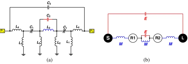
Figure 1. (a) Circuit model of the proposed tunableLC bandpass filter, (b) coupling topology.
2. FILTER DESIGN
Figure 1(a) shows the circuit model of the proposed bandpass filter based on LC resonators. In this model, L1, C1 and L2 constitute two resonators on both sides, and the resonator can be tuned by
changing the capacitance of C1. The two resonators are coupled by C2 and L3. C2 is very small;
therefore, a magnetic dominated mixed coupling between the resonators can be achieved. The fractional bandwidth of the filter is proportional to the coupling coefficient |k|, and the mixed coupling coefficient can be written as [1]:
|k|=|kM −kE| (1)
wherekM is the magnetic coupling coefficient, andkE is the electric coupling coefficient. Since the filter is tuned by the capacitorC1, the electric coupling decreases with the decrease of resonant frequency [6].
Therefore, the magnetic dominated mixed coupling is utilized to make the overall coefficient|k|increase with the decrease of resonant frequency [1], which can compensate bandwidth and meet the requirement of controllable fractional bandwidth. The input ports feed to the resonator through L4. Meanwhile,
C3 forms electric coupling between source and load. The coupling topology of the filter is shown in
Figure 1(b). R1 and R2 represent the two resonators. A π/2 or −π/2 phase shift can be obtained through the serious capacitive (electric) or inductive (magnetic) coupling, respectively. The phase shift of the resonator below resonance is π/2, and the phase shift of the resonator above the resonance is −π/2. Therefore, the phase shift from source to load through the coupling of resonators above the resonance is −π/2−π/2−π/2−π/2−π/2 =−π/2, and the phase shift from source to load through the coupling of resonators below the resonance is −π/2 +π/2−π/2 +π/2−π/2 =−π/2. Since the phase shift from source to load through the capacitive coupling is π/2, two transmission zeros can be generated beside the passband [23].
L1
C1
C2
L3
L2 L2 L1
C1
L1
C1
L2 L3/2 2*C2 L1
C1
L2
(c)
(a) (b)
Figure 2. (a) Coupling model of the resonators, (b) odd-mode, (c) even-mode.
The coupling model of the resonators is shown in Figure 2(a), and the odd-mode and even-mode circuit model are shown in Figures 2(b) and (c), respectively. Based on the proposed circuit model, the odd- and even-mode impedances Zr(e) and Zr(o) can be expressed as:
Zr(e) = jωL1+
1
jωC1
+ 1
jω2C2
jω1
2L3
Zr(o) = jωL1+
1
jωC1
+jωL2 (3)
When Zr(e) = 0 and Zr(o) = 0, the odd- and even-mode equivalent circuit work in resonant state, so the odd- and even-mode resonant frequencies can be obtained as
ωo =
−b−√b2−4ac
2a (4)
ωe =
1
C1(L1+L2)
(5)
where:
a = 2·L1L2L3C1C2,
b = −[2C2L2L3+2C1L1L2+C1L1L3+C1L2L3],
c = 2L2+L3.
The center frequency and mixed coupling coefficient can be written as:
ωc = √ωe·ωo (6)
|k| = ω
2
e−ω2o
ω2
e+ω2o
(7)
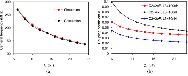
Based on the above discussion, numerical calculation and simulation are used to verify the tunable capability. The simulation is carried out by usingKeysight ADS (Advanced Design System). Capacitor
C1 is used as the tunable capacitor, and the element parameters of the proposed filter shown in
Figure 1(a) are: C2 = 2 pF, C3 = 0.2685 pF, L1 = 45 nH, L2 = 30 nH, L3 = 100 nH, L4 = 92 nH.
Figures 3(a) and (b) show the center frequency and coupling coefficient of the filter when capacitor C1
changes from 6 pF to 24 pF, respectively. It is shown that the central frequency of the filter can be tuned by the capacitor C1. The coupling coefficient can be increased when the central frequency decreases,
and the slope of the coupling coefficientkversus the central frequency can be controlled by the coupling capacitor C2 and coupling inductor L3. Therefore, the bandwidth of the filter can be compensated.
100 150 200 250 300
5 10 15 20 25
Cent er a l fr eq uen c y (MH z )
C1(pF)
Simulation Calculation 0 0.01 0.02 0.03 0.04 0.05 0.06 0.07 0.08 0.09 0.1
6 11 16 21
Coup lin g c o ef fi c ien t k
C1(pF)
C2=2pF, L3=100nH
C2=4pF, L3=100nH
C2=2pF, L3=80nH
(a) (b)
Figure 3. (a) Tunable center frequency, (b) coupling coefficientk.
3. FILTER SIMULATION
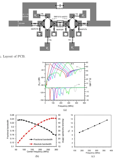
5.1pF at 0 V to 8 V reverse bias voltage. The inductors and capacitors are fromCoilcraft andAmerican Technical Ceramics. The passive microstrip structure is simulated by SONNET, and co-simulation is done by Keysight ADS (Advanced Design System). Figure 5(a) shows the simulated S-parameters of the tunable filter. It is shown that the passband of the filter can be tuned, and two transmission zeros are located at both sides of the passband to improve out-of-band rejection. The tuning range of center frequency is from 60 MHz to 300 MHz. Figure 5(b) shows the bandwidth versus tunable center
V Vc
2. 2.3 3 mm
2.
2.3 3 mm Vc
Vc Vc 0.8mm SMV1212 sot23*2 10k 06HP56N 600S2R2 06HP33N 06HP47N 06HP47N 06HP68N 06HP68N 10k 600S0R2 10k 10k
Figure 4. Layout of PCB.
Frequency (MHz) |S 21 | ( d B ) |S 11 | ( d B )
0 V 8 V
10 15 20 25 30 35 40 45 50 0.1 0.12 0.14 0.16 0.18 0.2 0.22 0.24 0.26
50 100 150 200 250 300
Ab s o lute ba ndw id th (M Hz ) Frac ti ona l ba ndw id th
Center frequency (MHz) Fractional bandwidth Absolute bandwidth 0 2 4 6 8 10 12 14 16
150 200 250 300 350 400
Qe
Frequency (MHz)
(c) (a)
(b)
frequency. It shows that the absolute bandwidth decreases from 46 MHz to 15 MHz, and the fractional bandwidth increases from 16% to 24% when center frequency decreases.
The external quality factorQe can be obtained by [21]:
Qe= ω
0·τs11(ω0)
4 =
2πf0·τs11(f0)
4 (8)
where τs11(f0) is the group delay of S11 at the resonant frequency f0. To study the external quality
factor of the filter, we extract half circuit of the filter, and the group delayτs11(f0) can be obtained via
simulations through ADS. Figure 5(c) shows Qe for the filter response. It is shown that Qe increases while the frequency increases, which will be helpful for compensating the absolute bandwidth [22].
4. FABRICATION AND MEASUREMENT
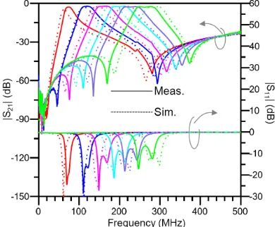
The fabricated filter is shown in Figure 6, and the filter size is 44 mm×30 mm. The frequency response of the tunable filter is measured by Keysight E5071C vector network analyzer. Figure 7 shows the measured and simulated S-parameters of the filter with the reverse bias voltage from 0 V to 8 V. Two transmission zeros are located at both sides of the passband. The rejection level is larger than 50 dB. Figure 8(a) shows the measured and simulated bandwidths versus center frequency. The simulation matches the measurement very well. It is shown that the absolute bandwidth is about 20 MHz to 55 MHz, the fractional bandwidth about 21% to 27%, and the fractional bandwidth compensated to a larger value at lower frequency. Figure 8(b) shows the measured insertion loss of the filter versus the center frequency. The center frequency tuning range is from 70 MHz to 270 MHz, and the insertion loss is less than 3 dB at all center frequencies. The comparison with related works is summarized in Table 1.
Figure 6. Fabricated tunable bandpass filter. Figure 7. MeasuredS-parameters.
Table 1. Comparison with related works.
Reference Order Tuning device Tunable range Bandwidth Insertion loss Size
[1] N = 2 Varactor diode 2.30–2.72 GHz 8%–8.5% 3.2–1.5 dB 24 mm×19 mm
[3] N = 3 DTC 0.41–0.82 GHz 54±12 MHz
(9±1%)∗ 6.5–4.9 dB 60 mm×68.5 mm
[20] N = 3 Varactor diode 1.75–2.25 GHz 9510 MHz+ 7.2–3.2 dB 10.4 mm×14.8 mm
This work N = 2 Varactor diode 0.07–0.27 GHz 20–55 MHz
(27%–21%)∗ 2.9–2.2 dB 44 mm×30 mm
(a) (b)
Figure 8. (a) Measured and simulated bandwidth versus the center frequency, (b) measured insertion loss versus the center frequency.
5. CONCLUSION
This paper has presented a tunable LC filter with magnetic dominated mixed coupling and electrical coupling between source and load, and two transmission zeros are generated based on cross-coupling. The magnetic dominated mixed coupling can be used to compensate the fractional bandwidth of the filter at lower band. The measured results show that the filter has achieved a tuning range from 70 MHz to 270 MHz, and the fractional bandwidth is from 27% to 21%. The proposed filter can be used in the reconfigurable RF front-end of frequency agile communication systems and frequency synthesizers.
ACKNOWLEDGMENT
This work was supported by the National Natural Science Foundation of China (NSFC) under Grant 61401375, 61504110, 61271090, 61531016, the Fundamental Research Funds for the Central Universities under Grant 2682014RC24, 2682015CX065, 2682015CX067 and the Sichuan Province Science and Technology Support Program 2015GZ0103, 2016GZ0059.
REFERENCES
1. Xiang, Q., Q. Feng, X. Huang, and D. Jia, “Electrical tunable microstripLC bandpass filters with constant bandwidth,” IEEE Transactions on Microwave Theroy and Techniques, Vol. 61, No. 3, 1124–1130, Mar. 2013.
2. Rais-Zadeh, M., J. T. Fox, D. D. Wentzloff, and Y. B. Gianchandani, “Reconfigurable radios: A possible solution to reduce entry costs in wireless phones,”Proceedings of the IEEE, Vol. 103, No. 3, 438–451, Mar. 2015.
3. Fu, M.-Y., Q.-Y. Xiang, D. Zhang, D.-Y. Tian, and Q.-Y. Feng, “A UHF third order 5-bit digital tunable bandpass filter based on mixed coupled open ring resonators,”Progress In Electromagnetics Research C, Vol. 64, 89–96, May 2016.
4. Gao, L., X. Y. Zhang, and Q. Xue, “Compact tunable filtering power divider with constant absolute bandwidth,”IEEE Transactions on Microwave Theory and Techniques, Vol. 63, No. 10, 3505–3513, Oct. 2015.
5. Liang, F., X. Zhai, W. Lu, Q. Wan, and Y. Zhang, “An independently tunable dual-band filter using asymmetric λ/4 resonator pairs with shared via-hole ground,”Progress In Electromagnetics Research, Vol. 146, 99–108, 2014.
7. Xiang, Q.-Y., Q.-Y. Feng, X.-G. Huang, and D.-H. Jia, “A novel microstrip LC reconfigurable bandpass filter,” Progress In Electromagnetics Research Letters, Vol. 36, 171–179, 2013.
8. Wang, Y., F. Wei, H. Xu, and X.-W. Shi, “A tunable 1.4-2.5 GHz bandpass filter based on single mode,” Progress In Electromagnetics Research, Vol. 135, 261–269, 2013.
9. Liang, F., W. Cai, W. Lu, L. Deng, and X. Zhai, “An independently tunable dual-band bandpass filter using a center shorting-stub-loaded resonator,” Progress In Electromagnetics Research C, Vol. 67, 31–40, 2016.
10. Ma, Y.-L., W. Che, J.-X. Chen, and W. Feng, “High selectivity balanced bandpass filter with tunable bandwidth using stub-loaded resonator,” Progress In Electromagnetics Research Letters, Vol. 55, 89–95, 2015.
11. Mohammadi, L. and K.-J. Koh, “2–4 GHz Q-tunable LC bandpass filter with 172-dBHz peak dynamic range, resilient to +15-dBm out-of-band blocker,”2015 IEEE Custom Integrated Circuits Conference (CICC), 1–4, 2015.
12. Mohieldin, A. N., E. Sanchez-Sinencio, and J. Silva-Martinez, “A 2.7 V, 1.8 GHz, 4th order tunable LC bandpass filter with ±0.25 dB passband ripple,” Proceedings of the 28th European Solid-State Circuits Conference, 343–346, Sep. 2002.
13. Zeng, K., D. Psychogiou, and D. Peroulis, “A VHF tunable lumped-element filter with mixed electric-magnetic couplings,”2015 IEEE 16th Wireless and Microwave Technology Conference, 1– 4, Apr. 2015.
14. Mohieldin, A. N., E. Sanchez-Sinencio, and J. Silva-Martinez, “A 2.7-V 1.8-GHz fourth-order tunable LC bandpass filter based on emulation of magnetically coupled resonators,”IEEE Journal of Solid-State Circuits, Vol. 38, No. 7, 1172–1181, Jul. 2003.
15. Testi, N., R. Berenguer, X. Zhang, S. Munoz, and Y. Xu, “A 2.4 GHz 72 variable-gain 100
dB-DR 7.8 mW 4th-order tunable Q-enhanced LC band-pass filter,” 2015 IEEE Radio Frequency
Integrated Circuits Symposium (RFIC), 87–90, Nov. 30, 2015.
16. Chen, C.-H., C.-H. Huang, T.-S. Horng, S.-M. Wu, J. Chen, C. T. Chiu, and C. P. Hung, “A novel compact LC resonator-based bandpass filter design with tunable transmission zeros,” 2008 Asia-Pacific Microwave Conference, 1–4, 2008.
17. Lee, H. S., D. H. Choi, and J. B. Yoon, “MEMS-based tunable LC bandstop filter with an ultra-wide continuous tuning range,”IEEE Microwave and Wireless Components Letters, Vol. 19, No. 11, 710–712, Nov. 2009.
18. Wong, S.-W., R.-S. Chen, J.-Y. Lin, L. Zhu, and Q.-X. Chu, “Substrate integrated waveguide quasi-elliptic filter using slot-coupled and microstrip-line cross-coupled structures,” IEEE Transactions on Components, Packaging and Manufacturing Technology, Vol. PP, No. 99, 1–8, Nov. 2016. 19. Ding, J., D. Liu, S. Shi, and W. Wu, “W-band quasi-elliptical waveguide filter with cross-coupling
and source-load coupling,”Electronics Letters, Vol. 52, No. 23, Nov. 2016.
20. Chiou, Y. C. and G. M. Rebeiz, “A quasi elliptic function 1.75–2.25 GHz 3-pole bandpass filter with bandwidth control,”IEEE Transactions on Microwave Theory and Techniques, Vol. 60, No. 2, 244–249, Feb. 2012.
21. Hong, J.-S. and M. J. Lancaster, Microstrip Filters for RF/Microwave Applications, John Wiley & Sons, Inc., 2001.
22. Zhou, W. J. and J. X. Chen, “High-selectivity tunable balanced bandpass filter with constant absolute bandwidth,”IEEE Transactions on Circuits and Systems II: Express Briefs, 2017 (IEEE Early access paper).