Patch Antenna for Full Duplex Application with Improved Isolation
Using Defected Ground Structure
Carlene Goodbody1, Nghi Tran2, and Tutku Karacolak1, *
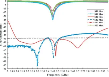
Abstract—A patch antenna system operating in the 2.4–2.5 GHz ISM band is proposed for in-band full duplex applications. The proposed antenna consists of a patch antenna, a modified 180◦ hybrid, and a defected ground structure. Fabricated prototype results show a measured bandwidth of 100 MHz and an isolation of −75 dB at the center frequency with an isolation of at least −50 dB covering the ISM band 2.4 GHz–2.5 GHz. The design also has a spherical directional radiation pattern, low cross polarization, and reasonable gain values.
1. INTRODUCTION
Available communication spectrums are facing increasing demands as the number of devices utilizing these frequencies become more numerous. Today the wireless spectrums support not just the traditional traffic but also manufacturing technology, wearables, vending machines, printers, headphones, televisions, medical diagnostic equipment, home monitoring systems, and much more. At minimum the typical household has five wirelessly connected devices and this number is growing exponentially [1]. This push towards a connected lifestyle has led to a very crowded set of radio spectra and the realization of limitations in current radio technology. As a result, researchers in both the industry and in academia are investigating new methods to arbitrate and decrease the present wireless spectral congestion. One of these proposed methods is full-duplex communication. A full-duplex radio is one that transmits and receives simultaneously over the same frequency band ideally allowing for twice the number of devices in an area. There are some challenges to accomplishing full-duplex operation. The largest of these is self-interference. In current antenna technology, the transmit signal overwhelms the received signal in duplex operation, resulting in a system that does not send or receive signals. To accomplish full-duplex this self-interference needs to be suppressed so that the desired signal gets through. A number of methods have been proposed to eliminate self-interference including metamaterials [2], combinations of digital and analog cancellation [3] as well as variations on monopole arrays and slot antennas [4]. In this work, we focused on improvement of self-interference suppression through the inclusion of a resonant defected ground structure (DGS). In [5], an antenna system was presented that proposes a cancellation technique using a patch design that utilized the characteristics of a modified 180◦ hybrid in a splitter/combiner configuration along with physical separation of the transmit and receive ports. This study utilizes the previous structure and includes a resonant DGS modeled around the microstrip line of the 180◦ ring hybrid to create built-in bandstop filters for additional cancellation.
2. ANTENNA DESIGN
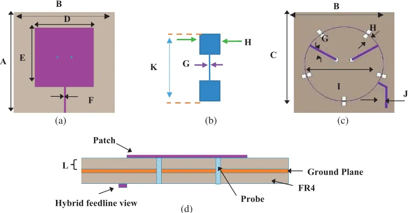
The designed antenna consists of a patch antenna and a modified 180◦ hybrid in the splitter/combiner configuration. As shown in Fig. 1, the antenna has three functional layers: A patch antenna is printed
Received 18 March 2019, Accepted 22 May 2019, Scheduled 30 May 2019
* Corresponding author: Tutku Karacolak ([email protected]).
Hybrid feedline view
Ground Plane L
FR4 Probe
(d)
Figure 1. (a) Top view of the antenna, (b) structure of DGS, (c) bottom views of the antenna, and (d) side view of the antenna.
on the top layer of the first substrate. The 180◦ ring hybrid is designed on the bottom side of the lower substrate. For both substrates, FR4-epoxy (εr = 4.4, tanδ = 0.02) with thickness 0.718 mm is used. The middle layer is a ground plane that has five square dumbbell lattice defects embedded symmetrically at 72◦ of separation from one another, with respect to the hybrid structure.
Defected ground structures are chosen for isolation improvements due to their natural resonant characteristics [6]. With appropriate placement and lattice selection DGS may be used to generate a phase difference through their ability to induce a slow wave effect in the resonator. The DGS accomplishes this by interrupting the return path of the current on the surface of the radiator forcing it to the periphery of the perturbation along the DGS side arms thereby increasing the path length of the current. This increase in the path length of the current results in an induced propagation delay and phase difference in the wave on the microstrip line. The DGS must be designed to resonate at the design frequency while providing sufficient length to generate the desired phase shift. The frequency characteristics are defined by two parameters, lattice shape and the gap distance, the connecting line between the lattice structures (Fig. 1(b)). These two structures define the effective inductance and capacitance induced by the whole DGS. The shape and dimensions of the defect effect how much it perturbs the currents in the radiator. We calculated the initial dimensions of the defect structures using band stop filter principles and lumped circuit analysis, λ8g where λg is the guide wavelength at cutoff frequency. The optimized values for the structure and antenna dimensions are reported in Table 1. Appropriate placement and lattice selection are very important, as an inappropriately placed or overly large lattice structure could negatively impact important design parameters such as radiation pattern and gain values. Therefore, an analysis of both numbers of DGS and DGS lattice shapes were conducted to first determine the optimum number of DGS and the DGS lattice configuration. As seen in Fig. 2(a), five dumbbell lattice defects separated at a 72◦ interval were found to be optimal for our
Table 1. Dimensions of antenna (in mm).
A= 46 B = 46 C = 42 D= 28.45 E= 28.85
F = 1 G= 0.05 H = 0.8 I= 16.5 J = 0.8
(a) (b)
Figure 2. (a) S-parameters for different numbers of DGS lattice. (b) S-parameters for various DGS lattice structures.
specific structure. Five defects provide efficient coverage of the hybrid microstrip line while avoiding the feed structures of both the patch and the hybrid, thereby avoiding unintended mismatches. In addition, the square dumbbell lattice offers the most effective perturbation and a better suppression for this geometry compared to other lattice shape structures (Fig. 2(b)). The antenna clearly achieves a higher isolation (S21<−60 dB) for square dumbbell lattice. The final dimensions given in Table 1 were refined by utilizing the built-in genetic algorithm optimization tool in ANSYS HFSS.
3. EXPERIMENTAL RESULTS
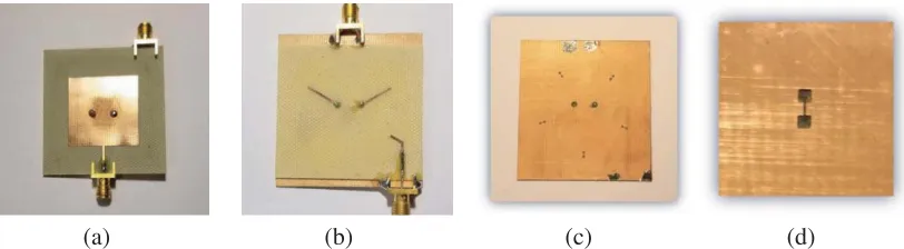
The design is simulated with ANSYS HFSS 19.1 and prototyped using an LPKF S63 milling machine. The fabricated antenna is shown in Fig. 3. Two 50 Ω copper zinc SMA connectors are used for the transmit and receive ports of the antenna. Measurements are performed in a highly reflective room to take into account environmental effects.
(a) (b) (c) (d)
Figure 3. Fabricated antenna: (a) top view, (b) bottom view, (c) ground plane with DGS structures, (d) DGS close up.
Figure 4. Simulated and measuredS-parameters.
(a) (b)
Figure 5. Simulated radiation patterns for (a) ϕ = 0◦, ϕ = 90◦ in transmit mode and (b) ϕ = 0◦, ϕ= 90◦ in receive mode.
Figure 5 shows the simulated co-polarized and cross-polarized radiation patterns of the antenna at 2.45 GHz for the x-z (φ= 0◦) andy-z (φ= 90◦) planes, respectively. The cross-polarization values in transmit mode are 40 dB lower than the co-polarization values at boresight, while in receive mode the difference between cross-polarization and copolarization values increase to 50 dB at boresight.
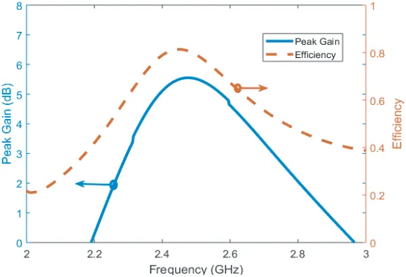
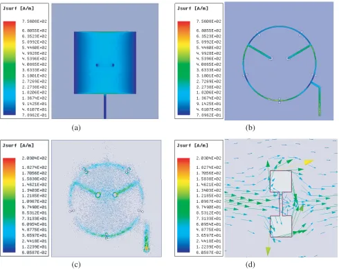
The three-dimensional gain patterns for both modes at 2.45 GHz are shown in Fig. 6. The peak gain of this antenna, atφ= 0◦ andθ= 0◦, is 5.5 dBi at its peak value for 2.45 GHz in transmit mode and approximately 5.6 dBi in receive mode, with an efficiency of approximately 80% between the frequencies of 2.35 to 2.45 GHz dropping to approximately 78% at 2.5 GHz the edge of our band of interest, as seen in Fig. 7. In Fig. 8 we see the surface currents in the patch, the hybrid and as seen by the ground plane in vector format, with a close up view of a single DGS lattice. Here it can be seen how the DGS lattice perturbs and changes the path length of surface currents thereby effectively suppressing unwanted surface waves and controlling the harmonics of the microstrip line optimizing the performance of the modified hybrid.
(a) (b)
Figure 6. Three-dimensional gain patterns at 2.45 GHz in (a) transmit mode and (b) receive mode.
Figure 7. Peak gain and efficiency.
(a) (b)
(c) (d)
Figure 8. Surface currents, (a) on the patch, (b) on the hybrid, (c) in vector format as seen by the ground, (d) close up view of a single DGS structure.
Table 2. Comparison of the proposed antenna with similar designs.
Design Maximum Measured Cancellation (dB)
Peak Gain (dBi)
Bandwidth
(MHz) Size (mm 3)
[4] 45 4 130 85×62×1.5
[5] 58 5 90 50×50×1.4
[7] 46 - 25 Antenna separation
>350 mm
[8] 54 6 60 50×50×2.2
[9] 40 2.7 55 22×59×0.8
4. CONCLUSION
A patch antenna, utilizing a modified ring hybrid feeding structure and DGS designed to act as an inter-structure band stop filter, is presented for full-duplex application in the ISM band of 2.4–2.5 GHz. A minimum isolation greater than 50 dB in the band of interest is measured in a highly reflective environment. It is clear from our investigation that DGS provides effective suppression of unwanted harmonics, surface waves, and other leakage transmissions. Further, it is clear that the DGS induces a bandstop response on the microstrip line of the hybrid improving isolation of the receive and transmit ports at the frequency of interest. The DGS has also improved the radiation characteristics of the system showing improved co-polarization and cross-polarization values over the previous model for both transmission and reception modes. The overall compact size of the antenna structure with its high isolation offers the potential to fit within small size full-duplex devices.
ACKNOWLEDGMENT
This work was supported by the National Science Foundation under Grant No. ECCS-1509052.
REFERENCES
1. Pew Research Center, “A third of Americans live in a household with three or more smartphones,” 2018, [Online], Available: http://www.pewresearch.org. [Accessed March 8, 2018].
2. Mao, C., Y. Yang, X. He, J. Zheng, and T. Liu, “Design of high-gain dual-band dual-circular-polarised antenna using reflective metasurface,” Electronics Letters, Vol. 53, No. 22, 1448–1450, 2017.
3. Quan, X., W. Pan, Z. Li, Y. Liu, and Y. Tang, “Hybrid SI cancellation for single-antenna full-duplex radios,”Electronics Letters, Vol. 53, No. 24, 1615–1617, 2017.
4. Makar, G., N. Tran, and T. Karacolak, “A high-isolation monopole array with ring hybrid feeding structure for in-band full-duplex systems,” IEEE Antennas and Wirless Propagation Letters, Vol. 16, 356–359, 2016.
5. Goodbody, C., T. Karacolak, and N. Tran, “Dual-polarized patch antenna for in-band full-duplex applications,” Electronics Letters, Vol. 54, No. 22, 1255–1256, 2018.
6. Weng, L. H., Y. C. Guo, X. W. Shi, and X. Q. Chen, “An overview of defected ground structure,”
Progress In Electromagnetics Research B, Vol. 7, 173–189, 2008.
7. Everett, E., A. Sahai, and A. Sabharwal, “Passive self-interference suppression for full-duplex infrastructure nodes,” IEEE Transactions on Wireless Communications, Vol. 13, No. 2, 680–694, 2014.
8. Makar, G., D. Kim, N. Tran, and T. Karacolak, “Compact antennas with reduced self interference for simultaneous transmit and receive,” Progress In Electromagnetics Research C, Vol. 78, 19–31, 2017.