Electronic Thesis and Dissertation Repository
2-18-2014
Control of Wind Energy Conversion Systems for Large-Scale
Control of Wind Energy Conversion Systems for Large-Scale
Integration with the Power System
Integration with the Power System
Omid Alizadeh
The University of Western Ontario
Supervisor
Dr. Amirnaser Yazdani
The University of Western Ontario
Graduate Program in Electrical and Computer Engineering
A thesis submitted in partial fulfillment of the requirements for the degree in Doctor of Philosophy
© Omid Alizadeh 2014
Follow this and additional works at: https://ir.lib.uwo.ca/etd
Part of the Power and Energy Commons
Recommended Citation Recommended Citation
Alizadeh, Omid, "Control of Wind Energy Conversion Systems for Large-Scale Integration with the Power System" (2014). Electronic Thesis and Dissertation Repository. 1907.
https://ir.lib.uwo.ca/etd/1907
This Dissertation/Thesis is brought to you for free and open access by Scholarship@Western. It has been accepted for inclusion in Electronic Thesis and Dissertation Repository by an authorized administrator of
LARGE-SCALE INTEGRATION WITH THE POWER SYSTEM
(Thesis format: Monograph)
by
Omid Alizadeh
Graduate Program in Electrical and Computer Engineering
A thesis submitted in partial fulfillment
of the requirements for the degree of
Doctor of Philosophy
The School of Graduate and Postdoctoral Studies
Western University
London, Ontario, Canada
c
This thesis is mainly focused on (i) mathematical modeling and real power control of a direct-drive wind energy conversion system (WECS) that employs a high-pole permanent-magnet synchronous generator (PMSG), and (ii) the contribution of the WECS to the frequency regulation process in a host power system. In the first part, a strategy is proposed for real power control of the WECS, which augments the maximum power-point tracking (MPPT) feature of modern WECSs. The proposed strategy is based on rapid torque control, rather than the (slow) pitch-angle control. Moreover, a supplementary damping scheme is presented and tuned for the proposed power control strategy, based on a detailed mathematical model and eigenvalue analysis of the WECS. The supplementary mechanism damps the WECS drive-train oscillations and maintains its internal stability, even if its output power is regulated. The thesis also presents an alternative control structure for the WECS which mitigates the sensitivity of the WECS output power to power fluctuations caused by wind speed variations and drive-train oscillatory modes. Thus, a damping strategy and a tuning procedure are proposed for the aforementioned control structure, such that a stable performance of the WECS over the operating range is ensured.
In the second part of the thesis, an enhanced control strategy is proposed that en-ables a WECS to contribute to frequency regulation process by effectively using its avail-able generation reserve and the kinetic energy of its rotor, such that the stability of the WECS is maintained over the operating range. The performances of direct-drive PMSG-based WECSs with the proposed control strategy are examined in an example host power system and the impact of wind speed intermittency on the frequency responses of WECSs is assessed, based on which the parameters of the proposed control are ad-justed to maintain the reliability of the example power system in response to a specific contingency event, under different wind speed regimes. The effectiveness of the proposed control strategies is demonstrated through time-domain simulation studies conducted in the PSCAD/EMTDC software environment.
Keywords: Control, Damping, Drive-Train Torsional Modes, Frequency Response, Grid Support, Power Electronics, Real Power Control, Voltage-Sourced Converter, Wind Energy Conversion Systems.
I would like to express my sincere gratitude to Dr. Amirnaser Yazdani for his excellent supervision, bright ideas, and continuous encouragement throughout the course of this research. It has been a great privilege for me to pursue my higher education under his supervision.
Also, the financial support provided by Dr. Amirnaser Yazdani and Western Univer-sity is gratefully acknowledged.
Abstract ii
Dedication iii
Acknowledgements iv
List of Figures ix
List of Tables xii
List of Appendices xiii
List of Abbreviations xiv
List of Nomenclature xv
1 Introduction 1
1.1 Introduction to Wind Energy Conversion Systems . . . 1
1.1.1 Wind Turbine Concepts . . . 2
Aerodynamic Drag and Lift . . . 2
Vertical-Axis and Horizontal-Axis Wind Turbines . . . 3
Number of Blades . . . 3
Betz Limit . . . 4
Upwind and Downwind Turbines . . . 4
1.1.2 Components of Wind Energy Conversion Systems . . . 5
1.1.3 Aerodynamic Torque Control . . . 5
1.1.4 Types of Wind Energy Conversion Systems . . . 6
1.1.5 Direct-Drive PMSG-Based WECSs . . . 8
1.1.6 Operating Regime . . . 9
1.1.7 Grid Integration Requirements of WECSs . . . 10
1.3.1 Real Power Control in WECSs . . . 14
Power Generation Control and Curtailment of WECSs . . . 14
Torsional Dynamics of Modern WECSs . . . 15
Multi-Mass Modeling of a WECS Drive-Train . . . 18
1.3.2 Frequency Regulation in Power Systems . . . 20
Power Balance Issue . . . 21
Frequency Regulation with CPPs . . . 22
Frequency Regulation with a High Penetration of Wind Power . . 25
1.3.3 Generation Reserves in Power Systems . . . 28
Generation Reserve and Wind Power . . . 28
Capacity Factor . . . 29
1.4 Thesis Contributions . . . 30
1.5 Thesis Outline and Related Literature Review . . . 31
Real-Power Control Strategies in WECSs . . . 32
Damping Drive-Train Torsional Modes . . . 33
Contribution of WECSs to Frequency Regulation . . . 34
1.6 Summary and Conclusion . . . 37
2 Real Power Control of a Direct-Drive PMSG-Based WECS 39 2.1 Introduction . . . 39
2.2 Structure of the Direct-Drive WECS . . . 40
2.3 Mathematical Model and Control Schemes . . . 41
2.3.1 Aerodynamic Model of the Turbine . . . 41
2.3.2 Drive-Train . . . 42
2.3.3 Permanent-Magnet Synchronous Generator . . . 42
2.4 Control Strategy and Modes of Operation . . . 45
2.4.1 MPPT Mode of Operation . . . 46
2.4.2 Controlled-Power Mode of Operation . . . 47
2.5 Eigenvalue Analysis . . . 48
2.6 Damping Strategy . . . 52
2.6.1 Structure . . . 52
2.6.2 Design . . . 52
2.6.3 Eigenvalue Analysis . . . 55
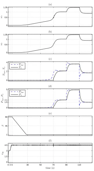
2.7.2 Response to Operation Mode and Wind Speed Changes . . . 62
2.8 Summary and Conclusion . . . 65
3 An Alternative Control Structure and Damping Strategy 66 3.1 Introduction . . . 66
3.2 Control Structure of the WECS . . . 67
3.3 Basic WECS Control . . . 68
3.3.1 Drive-Train Model . . . 68
3.3.2 Control for Fast dc-Link Voltage Regulation . . . 69
3.3.3 Control for Slow dc-Link Voltage Regulation . . . 70
3.4 Control Strategy to Damp the Drive-Train Torsional Modes . . . 73
3.4.1 Proposed Control Strategy . . . 73
3.4.2 Control Tuning Procedure . . . 75
1) Initial Values of Compensator Parameters . . . 75
2) Damping Gain . . . 75
3) Final Compensator Zero . . . 76
4) Final Compensator Gain . . . 77
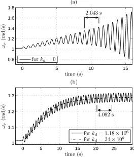
3.4.3 Behavior of the WECS under Different Compensator Gains . . . . 78
3.5 Simulation Results . . . 80
3.6 A Comparative Discussion on the Presented Control Strategies . . . 82
3.7 Summary and Conclusion . . . 84
4 Enhanced Control of WECSs for Contribution to Frequency Response 85 4.1 Introduction . . . 85
4.2 Control Strategy for Frequency Regulation . . . 86
4.2.1 Droop-Based Control . . . 87
4.2.2 Inertia-Emulating Control . . . 88
4.2.3 Pitch-Angle Control . . . 89
4.2.4 Description of the Proposed Control . . . 89
4.3 Case Studies . . . 91
4.3.1 Switched Model of the Example Wind Plant . . . 93
4.3.2 Power System with Only CPPs . . . 94
4.3.3 No Frequency Response from the Wind Plant . . . 95
4.3.6 Impact of Wind Speed Intermittency on Frequency Regulation . . 101 4.4 Summary and Conclusion . . . 105
5 Summary, Conclusion, and Future Work 106
5.1 Summary . . . 106 5.2 Conclusion . . . 107 5.3 Future Work . . . 108
A Parameters of the Example WECS in Chapters 2 and 3 110
B Analytical Forms of Matrices 112
C Parameters of the Example Wind Plant and CPPs in Chapter 4 115
Bibliography 117
Curriculum Vitae 125
1.1 Examples of wind turbine concepts [8]. . . 2
1.2 Main components of a wind energy conversion system. . . 5
1.3 Commercial configurations of wind energy conversion systems; a) type A, b) type B, c) type C, and d) type D. . . 7
1.4 Power curve of Vestas V90 3 MW wind turbine [18]. . . 10
1.5 The electrical frequency at the wind farm [25]; at t= 0.4 s the wind farm was disconnected from the transmission network. . . 16
1.6 Undamped oscillations of the rotor speed in a WECS without a damping mechanism. . . 18
1.7 A typical frequency response following a sudden loss of generation. . . 22
1.8 Tip-speed ratio control in a WECS. . . 32
1.9 Hill-climb search control in a WECS. . . 32
1.10 Power signal feedback control in a WECS. . . 33
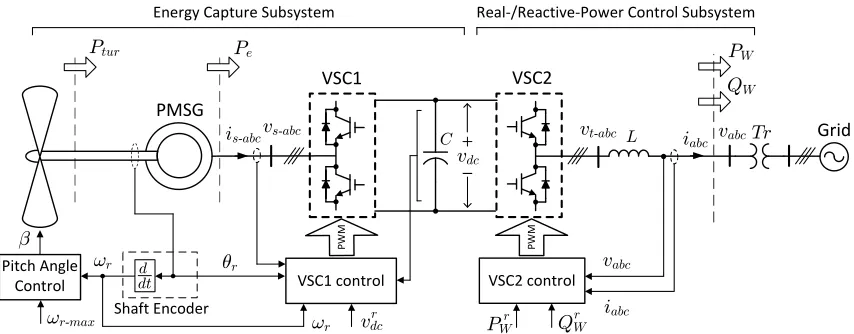
2.1 Simplified schematic diagram of the direct-drive WECS. . . 40
2.2 Block diagram of the PMSG torque control scheme. . . 43
2.3 Block diagram of the basic power control scheme. . . 45
2.4 Characteristic curves of a wind turbine for a wind speed and two different values of pitch angle. . . 47
2.5 Block diagram illustrating the generation of the power setpoint. . . 48
2.6 Absolute value of the real part ofA1 dominant eigenvalue as a function of kp3 and ki3. . . 50
2.7 Block diagram illustrating the implementation of the damping scheme. . 52
2.8 Control block diagram of the damping scheme. . . 52
2.9 Variations of the frequency of unstable mode as a function of the normal-ized power command in the CP mode of operation. . . 53
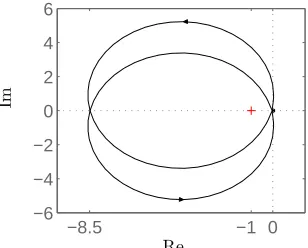
2.10 Nyquist plot of the open-loop frequency response of Figure 2.8, when C(s) =kd = 10 7 . . . 55
2.12 Migration plot of the eigenvalues for different operating points. . . 59 2.13 Response to operation mode change from MPPT to CP. . . 60 2.14 Start-up process and subsequent operation of the WECS in the MPPT
mode. . . 61 2.15 Response to changes in the operation mode and wind speed. . . 63 2.16 Response to changes in the operation mode and wind speed (cont.). . . . 64
3.1 Schematic diagram of the alternative control strategy for the direct-drive PMSG-based WECS. . . 67 3.2 Block diagram of the dc-link voltage control scheme. . . 68 3.3 Control block diagram of the energy capture subsystem. . . 70 3.4 Migration plot of the closed-loop poles without damping mechanism;
ar-rows illustrate increase inkc. . . 72 3.5 Migration plot of the closed-loop poles without damping mechanism; z =
3 ( trace),z = 4 (× trace),z = 5 (∇ trace), andz = 6 (+trace); arrows illustrate increase in kc. . . 73 3.6 Block diagram illustrating the implementation of proposed control scheme. 74 3.7 Control block diagram of energy capture subsystem with proposed control
scheme. . . 74 3.8 Migration plot of the closed-loop poles with the proposed control scheme;
arrows illustrate increase in kd. . . 76 3.9 Migration plot of the closed-loop poles with the proposed control scheme;
z = 3 ( trace), z = 4 (× trace), z = 5 (∇ trace), and z = 6 (+ trace); arrows illustrate increase in kd. . . 76 3.10 Migration plot of the closed-loop poles with the proposed control scheme;
arrows illustrate increase in kc. . . 77 3.11 Response to a change from the MPPT mode to the CP mode. . . 78 3.12 Response to a switch from the proposed control to the basic control. . . . 79 3.13 Migration plot of the closed-loop poles for different operating points. . . 80 3.14 Response to changes in operation mode and wind speed. . . 81 3.15 Responses to changes in power command under turbulent wind speed; (a)
with the control strategy presented in Chapter 2, (b) with the control strategy presented in this chapter. . . 83
4.2 Droop characteristic of the WECS. . . 87
4.3 Characteristic curves of a wind turbine for two wind speeds. . . 89
4.4 The example power systems. . . 92
4.5 Response of the example power system, with only CPPs. . . 94
4.6 Response of the example power system, without frequency response from the wind plant. . . 95
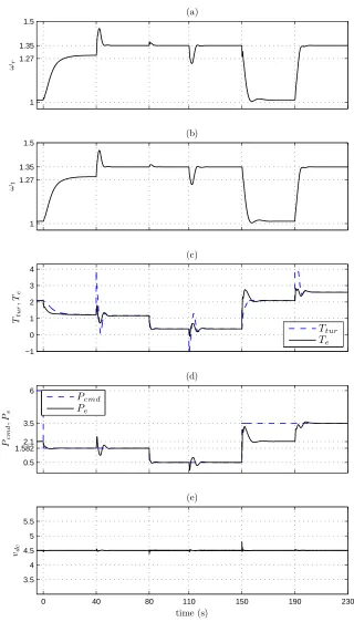
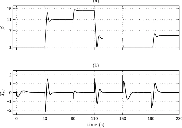
4.7 Response of the example power system, when the wind plant provides frequency response. . . 97
4.8 Frequency responses of the example power systems to the loss of CPP2. . 98
4.9 Proposed droop characteristic for the example wind plant. . . 99
4.10 Responses of the example power system to a sudden loss of CPP2, at different wind speeds. . . 101
4.11 Responses of the example power system to the wind speed intermittency. 103 4.12 Response of the example power system with different values of the inertia-emulating control parameters. . . 104
4.13 Frequency response of the system at different wind speeds. . . 105
1.1 Typical Inertia Constants of Different Power Plants . . . 26
2.1 Eigenvalues of the Energy Capture Subsystem. . . 51
2.2 Eigenvalues of the Energy Capture Subsystem with the Damping Scheme. 58 A.1 Wind Turbine Parameters . . . 110
A.2 PMSG Parameters . . . 111
A.3 Compensators and Other Parameters . . . 111
C.1 Conventional Power Plants Parameters . . . 115
C.2 Wind Plant Model - Turbine Parameters . . . 116
C.3 Wind Plant Model - Generator Parameters . . . 116
Appendix A Parameters of the Example WECS in Chapters 2 and 3 . . . 110 Appendix B Analytical Forms of Matrices . . . 112 Appendix C Parameters of the Example Wind Plant and CPPs in Chapter 4 . . . 115
AC Alternating Current
CP Controlled Power
CPP Conventional Power Plant
DC Direct Current
ERCOT Electric Reliability Council of Texas
HCS Hill-Climb Search
MPPT Maximum Power-Point Tracking
ROCOF Rate of Change of Frequency
TSR Tip-Speed Ratio
PI Proportional-Integral
PMSG Permanent-Magnet Synchronous Generator
PSCAD Power System Computer-Aided Design
PSF Power Signal Feedback
PSS Power System Stabilizer
PWM Pulse-Width Modulation
VSC voltage-sourced converter
WECS Wind Energy Conversion System
Cp Turbine power efficiency unitless
R Turbine radius m
β Turbine pitch angle degree
λ Turbine tip-speed ratio rad
ρ Air mass density kg/m3
vw Wind speed m/s
Ttur Turbine mechanical torque Nm
Ptur Turbine mechanical power W
Jt Turbine moment of inertia kgm2
Jr PMSG moment of inertia kgm
2
ωt Turbine angular speed rad/s
ωr PMSG angular speed rad/s
ks Drive-train stifness Nm/rad
γ Drive-train torsional displacement rad
p Number of PMSG pole pairs unitless
Ld Stator d-axis inductance H
Lq Stator q-axis inductance H
Rs Stator winding resistor Ω
θr PMSG rotor angle rad
vsd Stator d-axis voltage V
vsq Stator q-axis voltage V
isd Stator d-axis current A
isq Stator q-axis current A
λm PMSG maximum flux Wb
Te PMSG electrical torque Nm
Pe PMSG electrical power W
md d-axis modulating signal unitless
mq q-axis modulating signal unitless
PW WECS output real power W
QW WECS output reactive power Var
vdc dc-link voltage V
ω Power system angular frequency rad/s
f Power system frequency Hz
pG Number of pole pairs of a CPP unitless
JG Moment of inertia of a CPP kgm
2
Pmov Prime mover power of a CPP W
PG Output electrical power of a CPP W
PL Load real power W
Introduction
This thesis focuses on the real power control and frequency regulation with direct-drive wind energy conversion systems (WECSs) that employ high-pole permanent-magnet syn-chronous generators (PMSGs). Section 1.1 presents an introduction to WECSs and their integration into the power system. The remaining sections of this chapter outline the statement of problem, thesis objectives, background, thesis contributions, and the related literature review.
1.1
Introduction to Wind Energy Conversion
Sys-tems
Wind power has been a fast-growing alternative power source in the world. It is renewable and widely distributed. It also reduces toxic gas emissions. In 2012, global wind energy capacity grew by 19 percent, with the wind industry installing a record level of 44,711 MW of new clean wind power, and over 150,000 wind turbines operating around the world in over 90 countries [1]. In 2013, the global capacity growth rate has been above 14 percent [2].
Windmills have been utilized for irrigation pumping and milling grain since the 7th century AD [3]. The traditional windmills had typically four blades that provided a lattice framework over which the canvas sails could spread. In light winds, the whole blade area would be covered. In strong winds, the power output could be limited by only covering part of the blades. With a diameter typically of about 25 m, the traditional windmill could deliver a shaft power output of about 30 kW in a wind speed of about 7 m/s [4]. In a well exposed location, it would give an average power output of about 10 kW.
Figure 1.1: Examples of wind turbine concepts [8].
However, steam engines became progressively more efficient and more economic as the 19th century advanced. Because steam engines could also provide power on demand, the use of windmills went into decline. This decline was accelerated by the later development of internal combustion engines and by the trend in fossil fuels which became more readily available and less costly. Since 1973, the trend of decreasing fuel prices has been sharply reversed, and it is now accepted that the era of very cheap fuel has ended. This trend in addition to the global efforts in reducing greenhouse gas emissions mainly caused by fossil fuels has resulted in investing increasingly in renewable energy sources. Among the various types of renewable energy, wind energy is now emerged as one of the most promising of the renewable energy technologies. It is predicted that by 2020 up to 12% of the worlds electricity will be supplied from wind energy [5].
1.1.1
Wind Turbine Concepts
Wind turbines are mechanical devices specifically designed to convert part of the kinetic energy of wind into useful mechanical energy. Since the beginning of wind turbine devel-opment, various concepts and designs have been developed. In the following, a general overview of wind turbine concepts is presented.
Aerodynamic Drag and Lift
and, hence, lifts the blade. The same principle allows airplanes to fly. The turbines that achieve their driving power from the lift force have higher angular speeds as compared to the ones based on the drag force, and are well suited for electricity generation. In general, lift-driven turbines are more efficient than their drag-driven counterparts [7].
Vertical-Axis and Horizontal-Axis Wind Turbines
Wind turbines can be further divided into vertical-axis and horizontal-axis turbines based on the orientation of their spin axis. In a vertical-axis turbine, the blades rotate about an axis perpendicular to the ground. The most common designs are the Darrieus (curved blades), Giromill (straight blades), and Savonius (scoop blades) [Figure 1.1]. Vertical-axis turbines have the advantage of operating independently of the direction of wind. Moreover, the gearbox and generating machinery can be placed at the ground level. However, their major disadvantages are high torque fluctuations with each revolution, no self-starting capability, and limited options for speed regulation in high wind speeds [6]. In a horizontal-axis turbine, the blades rotate about an axis parallel to the ground and wind flow. Common examples are the old-style Dutch windmill and modern wind turbines [Figure 1.1]. A horizontal-axis turbine consists of a tower and a nacelle that is mounted on top of the tower. The nacelle contains the generator, the gearbox and the rotor. Nowadays, nearly all modern commercial wind turbines connected to grid are horizontal-axis turbines. One reason is that they are more suitable for harnessing the higher and smoother wind at higher altitudes. Different mechanisms exist to point the nacelle towards the wind direction or to move the nacelle out of the wind in case of high wind speeds. In the small turbines, the rotor and the nacelle are oriented into the wind with a tail vane. In the large turbines, the nacelle with the rotor is electronically yawed into or out of the wind in response to a signal from a wind vane.
Number of Blades
swept area. A wind turbine with a high number of blades has a low angular speed but a high mechanical torque. In contrast, a wind turbine with only two or three blades has a higher angular speed which allow the use of a smaller and lighter gearbox to achieve the required high speed at the driving shaft of the power generator. Currently, three-bladed turbines dominate the market for grid-connected horizontal-axis wind turbines.
Betz Limit
An important operational characteristic of wind turbines is the Betz limit. It indicates the theoretical maximum possible energy that the turbine can extract from the wind. If turbines were 100% efficient, which is practically impossible, all the airflow energy would be extracted and the flow speed after passing through the turbine would be zero. In 1928, Betz showed that under ideal assumption of uniform rotor disk with infinite number of blades the maximum efficiency of a turbine is 59.3% [3]. In practice, this coefficient is less due to non-ideal conditions such as wind shade behind the rotor, finite number of blades, blade-tip losses, and frictional drag. Present wind turbines have an efficiency around 52%-55% [6].
Upwind and Downwind Turbines
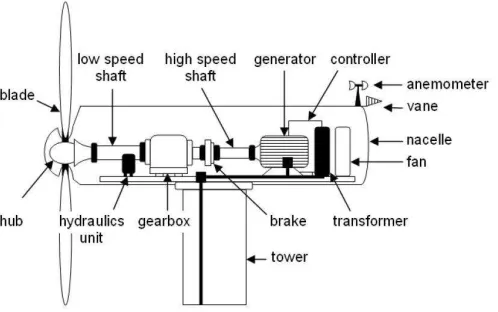
Figure 1.2: Main components of a wind energy conversion system.
1.1.2
Components of Wind Energy Conversion Systems
The main components of a WECS is shown in Figure 1.2. The turbine consists of the blades, the hub, and the connecting components including bearings and pitching actu-ators. The turbine transforms the kinetic energy of wind into mechanical energy. In multi-megawatt turbines, the blades can be over 60 meters in length [6].
The drive train is formed by the turbine rotating mass, low-speed shaft, gearbox, high-speed shaft, and generator rotating mass. It transfers the turbine mechanical energy to the generator shaft where it can be converted to electrical energy. A gearbox is required between the turbine and the generator, because the angular speed of the turbine is much lower than that of the generator. However, a gearless configuration can also be developed by increasing the number of generator pole pairs. For multi-megawatt turbines the gearbox ratio is about 50-100, because the typical speed range of the turbine is 10-20 rpm, whereas for the generator it is about 1000-2000 rpm [3]. For smaller WECSs, the turbine speed is higher and, therefore, the gearbox ratio may be less than 50. The low-speed shaft contains pipes for the hydraulics system that operate the aerodynamic brake. The high-speed shaft is equipped with an emergency mechanical brake that is used in case of failure of the aerodynamic brake. Other components include the anemometer and vane which respectively measure the speed and direction of wind. Devices such as electric fans and oil coolers are used to cool the gearbox and generator.
1.1.3
Aerodynamic Torque Control
is facing the wind to extract the maximum possible energy. This is performed by rotat-ing the nacelle about the tower axis. Reduction of input aerodynamic torque is usually obtained by the blades. In stall-controlled turbines, the blade cross section is designed such that above a certain angular speed the blades enter a stalling mode. The counter-part of stall-controlled turbines are pitch-controlled turbines. In this configuration, the aerodynamic torque is regulated by pitching the blades to feather, i.e., by reducing the angle of attack. Pitch-regulated turbines can be active or passive pitch controlled. In the former case, a controllable pitching mechanism (usually a hydraulics system) is in place. In the latter case, the blades are mounted on the hub such that the thrust force pitches the blades, i.e. the blades are self-pitched [7].
The advantage of stall regulation is that a complex control for blade pitching is not required. The aerodynamic and structural design of the turbine are, however, more complex. Nowadays the trend is to use pitch-controlled turbines due to their enhanced performance and less mechanical loads. The pitch angle in large modern turbines cannot change immediately but only at a finite rate, which might be low due to the size of turbine blades. The rate of change of the blade pitch angle is in the range of 3-10 degrees per second, depending on the size of the wind turbine [6].
1.1.4
Types of Wind Energy Conversion Systems
There are mainly four types of WECSs [Figure 1.3] which has been used commercially at the utility level and are introduced in the following [10]:
• Type A: Fixed-Speed WECS
(d)
Grid
(a)
Grid
Gearbox SCIG
PMSG WRSG WRIG
Capacitor Bank
(b)
Grid
Gearbox WRIG
Capacitor Bank
(c)
Gearbox DFIG
Grid
Gearbox
Figure 1.3: Commercial configurations of wind energy conversion systems; a) type A, b) type B, c) type C, and d) type D.
is able to provide reactive power and maintain a satisfactory voltage profile. The disadvantages of this type are the requirement for reactive power compensation and soft-starters and that the voltage quality is easily deteriorated in weak networks.
• Type B: Variable-Speed WECS with Variable Rotor Resistance
This configuration is in principle the same as the one in type A; however, a wound rotor induction generator with external rotor resistance is utilized in this configu-ration. This type allows variable-speed operation in a limited range of up to 10% above the grid angular frequency. A capacitor bank is also used in this type for power factor correction. The advantage of this type is its larger slip range com-pared to type A and a simpler control structure comcom-pared to the following two other types. It has, however, the same problems as type A. Moreover, compared to type A it has increased losses due to the larger rotor resistance.
• Type C: Variable-Speed WECS with Doubly-Fed Induction Generator
the electrical torque, and the ability to control reactive power independently. The smaller power-electronic converter makes this type attractive from an economic point of view compared to a WECS with a full-scale converter, which is explained next.
• Type D: Variable-Speed WECS with a Full-Scale Converter
This configuration provides a pitch-controlled variable-speed operation over the en-tire speed range of the generator. Moreover, the full-scale converter ensures reactive power compensation and smooth grid connection. The generator can optionally be an asynchronous or synchronous generator. The generator can be excited electri-cally (wound rotor synchronous generator or wound rotor induction generator) or by a permanent magnet (permanent-magnet synchronous generator). Typically, a direct-drive high-pole synchronous generator is employed which eliminates the use of the gearbox due to the low-speed operation of the generator. Synchronous gen-erators are suitable for higher power applications as they operate at unity power factor. The main advantage of this type is the complete decoupling of the generator from the grid which can facilitate the control of the WECS under disturbances from wind or the grid. The main disadvantage is the higher cost of the large converter.
Before 2001, types A and B were the dominant technologies of the grid-connected WECSs. However, type B is not offered any more and type A is being phased out of the market, in particular in the area of multi-megawatt WECSs [10]. The present trend in the industry is to use variable-speed WECSs due to their superior annual power production, which exceeds by 5 to 10 percent from those of fixed-speed WECSs [11]. This improvement in efficiency is, however, obtained at the cost of greater complexity in the construction of the unit and also some additional losses in the power-electronic converters (which enable the variable-speed operation). Moreover, the advances in semiconductors technology make utilizing power-electronic converters in WECSs economically justifiable. Thus, the most recent installed WECSs are dominated by types C and D.
1.1.5
Direct-Drive PMSG-Based WECSs
interest in the recent years, especially for offshore applications where a low maintenance solution is an attractive option. Moreover, the higher efficiency of a WECS with gearless drive-train results in achieving about 3 to 5 percent higher energy production compared to a similar WECS with gearbox [13]. To provide high torque at low angular speeds, the direct-drive configuration requires the generator to have a large number of poles and, thus, a large diameter. Permanent magnet excitation for synchronous generators allows for small pole pitch and can yield cost-effective designs [14]. Other advantages of a PMSG compared to an electrically-excited synchronous generator are: lighter weight, no additional power supply for the field excitation (which results in a higher reliability due to the lack of slip rings), improvement in the efficiency, higher energy yield, and higher power to weight ratio [15]. The disadvantages of a PMSG are that its excitation cannot be controlled and it is more expensive.
In this thesis, a direct-drive WECS is utilized which employs a high-pole PMSG. The choice is based on the expectation that this class of WECSs will be widely deployed in the future, due to its simple and low-loss generator, and gearless, maintenance free, light, and quiet drive-train (specially for offshore applications in which the maintenance is extremely expensive and complex) [16].
1.1.6
Operating Regime
The main turbine specifications are determined following from the choice of the turbine rotor diameter. The turbine tip speed is restricted to meet the acceptable noise level emitted from the turbine. From the maximum allowed tip speed and the desired power capacity, the rated angular speed of the turbine is determined. However, in offshore applications the noise emission (which is dominated by the rotor and increases with the square of the rotor speed) is not a design driver and the turbine could operate at higher rotor speeds that result in higher energy extraction capabilities (with the same rotor diameter) [17].
The operating regime of a wind turbine can be illustrated by its power curve, which plots its estimated output power as a function of wind speed. An example of a wind turbine power curve is shown in Figure 1.4. The power curve gives three important values [3]:
• Cut-in wind speed: minimum wind speed at which power generation is reasonable.
Cut-in
Wind Speed Wind SpeedRated Wind SpeedCut-out
Figure 1.4: Power curve of Vestas V90 3 MW wind turbine [18].
(which is often but not always the maximum power).
• Cut-out wind speed: wind speed at which the turbine is shut down (with automatic brakes and/or blade pitching) to protect the turbine from mechanical damage.
Below rated wind speed, the WECS is operating in partial-load regime. Above rated wind speed, the WECS is operating in full-load regime. In each operating regime the WECS can be controlled in various ways to achieve specific objectives. The primary goals are to maximize the captured energy in the partial-load regime and to limit the captured energy to its rated value in the full-load regime. The pitch angle is usually maintained at its minimum in the partial-load regime to allow maximum energy extraction from wind and to limit the mechanical wear of the pitching mechanism. At a certain wind speed, the WECS controller must limit the output power by changing the pitch angle.
1.1.7
Grid Integration Requirements of WECSs
In the early days, small fixed-speed WECSs were scattered over the distribution network and the integration issues were mainly related to voltage and power quality problems such as [19]:
• Steady-state voltage change,
• Voltage flicker,
The shift towards the variable-speed WECSs has alleviated some of the above inte-gration issues because variable-speed WECSs have smoother output power, use modern power electronics, and are able to control their power factor. However, new integration issues emerged because of the increasing size and geographic concentration of modern WECSs. The difficulties of wind power integration depend mainly on the grid strength. In a weak network, the penetration of wind power is limited, typically because the security and reliability of the grid cannot be maintained economically.
In the recent years, the grid codes established for most countries require the larger WECSs to behave similar to conventional power plants. The major requirements of typical grid codes for operation and grid connection of WECSs are summarized as follows [20]:
• Voltage operating range: WECSs are required to operate within typical grid voltage variations.
• Frequency operating range: WECSs are required to operate within typical grid frequency variations.
• Real-power control: WECSs are required to provide real-power control to improve the system stability and to prevent overloading of lines; WECSs are also required to respond with a ramp rate in the desired range.
• Frequency control: WECSs are required to provide frequency response capability to help maintain the desired network frequency.
• Reactive-power control: WECSs are required to provide dynamic reactive-power control capability to maintain the reactive power balance and the power factor in the desired range.
• Voltage control: individual WECSs are required to control their own terminal volt-age to a constant value by means of an automatic voltvolt-age regulator.
• Low-voltage ride through: in the event of a voltage sag, WECSs are required to remain connected to the grid for a given time period before being allowed to dis-connect; moreover, some utilities require that the WECSs help support grid voltage during faults by supplying reactive power.
• Power and voltage qualities: WECSs are required to provide the electric power with desired power and voltage qualities, e.g., maintaining voltage fluctuations and current harmonics in the desired range.
• WECS modeling and verification: some grid codes require wind farms owners to provide models and system data, to enable the system operator to investigate the interaction between a wind farm and the power system, by running simulations; they also require installation of monitoring equipment to verify the actual behavior of a wind farm during faults and to check the model.
• Communications and external control: wind farms operators are required to provide signals corresponding to a number of parameters which are important for the system operator, to enable proper operation of the power system; moreover, it must be possible to connect and disconnect the wind farm remotely.
The aim of these grid codes is to ensure that the continued growth of wind power does not compromise the power and voltage qualities of the electric power system, nor its security and reliability. Grid code requirements and regulations vary considerably from region to region. The differences in the requirements are due to the different wind power penetration levels and different degrees of power network robustness.
In this thesis, the technologies and solutions for operation and grid integration of direct-drive PMSG-based WECSs are studied to meet the grid codes related to output real-power control and frequency regulation requirements.
1.2
Statement of Problem and Thesis Objectives
Operators of the power systems with high wind power penetration encounter new challenges to maintain the reliability and stability of the grid. Therefore, new grid con-nection requirements have been established for WECSs. Modern WECSs are requested to act as active components in the grid and to take over control tasks, which are tradition-ally performed by CPPs. System operators should be able to control the output power of modern WECSs, to more effectively take part in the control of the power system, such as the frequency regulation. WECSs with controllable output power capability can help to improve the power quality in the power system, and have potential applications in the situation of large wind power penetration. These requirements introduce new challenges to the control of WECSs. Extensive research and development efforts have been carried out to introduce new technologies and control strategies for modern WECSs to resolve the technical issues associated with the ever-increasing wind power incorporation. More-over, direct-drive variable-speed WECSs that employ high-pole PMSGs are expected to be widely deployed in the future, due to their low-loss generators, low maintenance re-quirements, and quiet drive-trains, which calls for studying their capabilities in meeting the new requirements.
The objectives of the thesis are:
• To develop a mathematical model for a direct-drive PMSG-based WECS and to introduce a strategy to control its output real power, which augments the maximum power-point tracking (MPPT) feature of modern WECSs.
• To enhance the aforementioned power control strategy by supplementing a damping mechanism, which enables rapid control of the WECS output power while the drive-train torsional modes are well damped, and to tune the parameters of the control scheme based on the eigenvalue analysis of the WECS.
• To introduce an alternative control strategy for the direct-drive PMSG-based WECS which mitigates the sensitivity of the WECS output power to power fluctuations caused by wind speed variations and drive-train oscillatory modes, while enables the WECS to damp its drive-train oscillations and maintain internal stability, even if its output real power is regulated, and to ensure a stable performance of the WECS over the operating range.
the kinetic energy of its rotor, such that the stability of the WECS is maintained, under different wind speed regimes.
• To introduce a procedure to ensure a reliable operation of a power system with large integration of wind power by taking into account the intermittency of wind and its impact on the power system frequency regulation.
1.3
Background
1.3.1
Real Power Control in WECSs
The pervasive penetration of wind power into the electric grid indicates that WECSs should also be able to take part in the power-flow control process which, presently, is exclusively undertaken by the CPPs; the feature should retain the MPPT capability that modern WECSs currently possess. WECSs with controllable output power can help to improve the power quality in the grid and have potential applications in the situation of large wind power penetration [21].
Power Generation Control and Curtailment of WECSs
Renewable energy sources like wind power have priority access to the grid due to their marginal price of almost zero, i.e., other generation sources must restrict their production [22]. However, curtailment of the wind power production may be required at certain conditions and can reduce the overall system integration costs. Curtailment of wind power could mainly arise because of network limitations or system aspects [23].
Examples of wind power curtailment because of network limitations are:
• Local limitations could give rise to a need to constrain the output of a group of WECSs. The connection of WECSs is normally planned so that constraints are not required under the conditions covered by the planning criteria. However, conditions not covered by the criteria may arise from time to time.
• The time frame from application to connection of a wind farm can be down to a year, whereas the time frame from planning to commissioning of new transmission lines might be a decade.
• At times of low power demand in the power system, a minimum level of CPPs must be kept connected to ensure the stability and reliability of the power system. Therefore, the surplus wind power production may be curtailed.
• Due to the risk of reduction in the available wind power production at the same time as the power demand rises, wind power may have to be constrained to ensure that the load gradient that must be met by the remaining power plants is within their dynamic capacities.
• In case the wind power production exceeds power demand plus interconnection capacity or cannot be accommodated by the transmission or distribution system, the generation surplus must be removed.
• Modern WECSs are capable of going from partial load to full power within a very short time, given the necessary wind conditions. This makes wind power a valuable asset for fast regulation.
Torsional Dynamics of Modern WECSs
The torsional dynamics of the modern WECSs differ from the conventional turbine gener-ators. WECSs are the only generation units in the utility network where the mechanical stiffness is lower than the electrical stiffness [24]. The electrical stiffness represents the torsional dynamics of a generation unit drive-train as a whole, against the synchronous power system, whereas the mechanical stiffness represents the interactions among the different components of the drive-train in the generation unit. The lower mechanical stiffness of modern WECSs is due to the large diameter of their turbines that is required to capture more energy from the wind.
One of the first experiments that indicated the soft coupling between the turbine and the generator in fixed-speed WECSs was the islanding experiment carried out at the Rejsby Hede wind farm [25]. During the experiment, the wind farm was disconnected from the transmission network. This islanded operation continued for less than one second before the WECSs were tripped and the turbines were stopped. During the islanded operation, the electrical frequency showed an oscillatory behavior [Figure 1.5]. The natural frequency of these oscillations was 1.7 Hz which corresponded to the drive-train torsional modes of the WECSs [26].
Figure 1.5: The electrical frequency at the wind farm [25]; at t = 0.4 s the wind farm was disconnected from the transmission network.
affect the dynamic performance of the WECS [27]. A larger diameter of the turbine results in drive-train torsional modes with lower frequencies, which may lead to instability of the WECS or its interaction with the low-frequency modes of the electrical power system. Therefore, it is important to take the torsional modes of the drive-train in modern WECSs into consideration. In fixed-speed induction generator based WECSs, the induction generator acts as an effective damper, which helps to reduce the magnitude of the drive-train oscillations. However, it has been reported that these oscillations are still significant and must be taken into account when analyzing the dynamic performance of fixed-speed WECSs in transient stability studies [28]. In case of the variable-speed WECSs which operate at a controlled torque, the damping contribution of the generator is low because the torque no longer varies as a function of the rotor speed. Therefore, damping techniques are required to be incorporated in the control system of variable-speed WECSs.
Reference [29] reports that the equivalent stiffness of a WECS drive-train is inversely proportional to the square of the number of the generator pole pairs and, therefore, is low in a WECS with a high-pole PMSG. In other words, a larger number of generator pole pairs results in a softer driven-train, according to
keq = κ
p2 , (1.1)
Nm/rad) calculated as [30]
κ= GπD
4 sh
32L , (1.2)
where Dsh is the shaft diameter, Lis the shaft length and Gis the shear modulus. Equation (1.1) implies that any twist of the mechanical shaft results in a larger dynamic change of the electrical rotor angle for generators with a larger number of pole pairs. However, in a direct-drive WECS, the shorter length of the mechanical shaft between the turbine and the generator due to the elimination of the gearbox increases the stiffness to some extent. In conclusion, the drive-train torsional modes in a direct-drive WECS that utilizes a high-pole PMSG may significantly affect the operation of the whole WECS. Due to the torsional characteristic of the drive-train, the rotor speed is prone to oscillation whenever the system gets excited by mechanical or electrical load changes [31]. The torsional modes may lead to fluctuations in the dynamic performance of the WECS and may increase the mechanical fatigue of the drive-train. These oscillations are typically in the range of 0.1 Hz-10 Hz [32]. Consequently, a single-mass or lumped model of the drive-train is insufficient to analyze the transient behavior of a WECS, as reported in reference [33], and may result in significant errors. Therefore, a multi-mass model should be considered for the drive-train of modern WECSs.
The variable-speed generator in a direct-drive PMSG-based WECS is connected to the grid via a full-scale converter. Therefore, the generator is decoupled from the electric grid and, thus, the strong torsional damping characteristics which are inherent to ac-connected generators are lost [34]. Moreover, the frequency at the terminals of the PMSG in such a configuration is changing freely with the rotor speed. Hence, even in case of transient load changes there is no relative movement between the rotor field and the stator field that could induce a current into the damper windings. As a result, no damping torque is provided to counteract the rotor speed oscillations. Figure 1.6 shows how the rotor speed of a WECS oscillates with gradually increasing oscillation amplitude, causing the WECS to break down eventually.
The absence of any damping mechanism might lead to self-excitation and even insta-bility of the WECS. Moreover, as the tendency to build larger WECSs at competitive costs encourages lighter and, consequently, more flexible drive-trains, the aspect of de-veloping control strategies with damping capabilities as an explicit objective of a modern WECS control algorithm becomes increasingly important [35].
0 1 2 3 4 5 6 7 0.6
0.8 1 1.2 1.4
time (s) ωr
(r
a
d
/
s)
Figure 1.6: Undamped oscillations of the rotor speed in a WECS without a damping mechanism.
However, damping by means of blade pitching, as suggested in reference [36], is a very inefficient way of influencing the drive-train torsional modes. It may also be possible to provide some damping using extra hardware mounted on the drive-train [37], which is costly and needs extra devises. Another solution is to modify the control scheme of a WECS in order to provide sufficient damping [34]. The main idea is to suppress the rotor speed oscillations by supplementing the control system with a damping scheme.
Multi-Mass Modeling of a WECS Drive-Train
The two-mass model of the power producing WECSs was first suggested in [24] to study the drive-train torsional modes of grid-connected WECSs. Reference [28] discusses that a two-mass representation of the drive-train is necessary for the stability analysis of a WECS to accurately capture the effects of the electromechanical interactions. Higher-order representations of the drive-train dynamics have also been considered in the lit-erature. However, because a high-order drive-train model may not be suitable for in-vestigating the transient stability of the WECSs in large power system studies, different representations of the drive-train dynamics are studied in literature to evaluate how they affect the performance of the WECSs during electrical transients and to assess the ac-curacy of representing the drive-train dynamics with a reduced-order two-mass model in transient stability studies.
distribution, for simplicity. Hence, the weight of the three blades is combined to make a single mass and the turbine torque is considered to be equal to the aggregate of the torques acting on the three blades. Detailed transformation from the six-mass model to a three-mass model is presented in reference [39]. The model is further reduced to a two-mass drive-train model. In the two-mass model, one mass represents the turbine inertia which can be calculated from the combined weights of the three blades and the hub, and the second mass represents the inertia of the gearbox and the generator. The gearbox divides the drive-train into low-speed and high-speed shafts. The stiffness of the low-speed shaft is considered as the drive-train stiffness in the reduced-order two-mass model. The behavior of the WECS in response to an electrical disturbance is compared when using a six-mass, a three-mass and a reduced-order two-mass model of the drive-train. The study concludes that a reduced-order two-mass model of the drive-train is sufficient, with reasonable accuracy, for the transient stability analysis of a WECS.
Reference [27] introduces a three-mass model for a WECS drive-train which takes into account both torsional flexibilities of the shaft and bending flexibilities of the blades. The parameters of the three-mass model are derived by matching the mathematical equations of the three-mass model with the frequency spectrum result (which is achieved by running an experimental test on the WECS). Based on the derived three-mass model, it is concluded that the effective flexibility of the blades is 0.4 times larger than the flexibility of the shaft, i.e., the blade flexibility is more important than that of the shaft. However, representation of both shaft and blade flexibilities increases the order of the model, which may not be desirable for stability studies of WECSs in a large power system. Moreover, for the dynamic studies of a WECS, the torsional mode that has less damping and is likely to be the most significant is the one with the lowest frequency. Therefore, instead of neglecting the effect of the blade or shaft flexibilities, an effective two-mass model is obtained in [27], which takes into account both shaft and blade flexibilities but only represents the dominant low-frequency torsional mode of the drive-train.
In conclusion, regardless of various approaches in calculating the parameters of the drive-train model, there is a major consensus that a two-mass model is adequate for capturing the dynamics that affect stability; higher-order models are commonly employed for studying the mechanical fatigue of the turbine drive-train.
the frequency described as
fosc= 1 2π
s
ks Jeq
, (1.3)
where Jeq is the equivalent drive-train moment of inertia which is determined by
Jeq=
JtJr Jt+Jr
, (1.4)
parameters Jt and Jr respectively signify the turbine and generator moments of inertia (in kgm2
). The torsional mode of (1.3) could be excited by a rapid torque change on either end of the drive-train system.
In the mechanical system of a WECS, the damping factors include [40]:
1. The mass damping factor, which is the damping element of the individual masses. This damping factor is mostly attributed to the friction of bearings. The bearing system in a WECS mechanical drive-train is usually oiled. Therefore, the friction is small and, consequently, this damping is neglected in this thesis.
2. The shaft damping factor, which is the mutual damping between adjacent masses. This damping factor is attributed to the shaft material and is negligible and, thus, the damping effect due to this factor is also not taken into consideration in this thesis.
1.3.2
Frequency Regulation in Power Systems
the potential of WECSs to participate in frequency regulation process. Modern WECSs should not degrade the stability of the existing power system, but should, if possible, contribute to increase the stability by actively providing frequency response upon request. Consequently, the output real power of the WECSs should be controllable such that a wind generation reserve could be maintained for frequency response.
The power balance issue in a power system is discussed next. Then, the mecha-nism of frequency control in power systems with and without wind power penetration is presented.
Power Balance Issue
The function of an electrical power system is to produce electricity from its available sources and transport it to the points of consumption. Electricity has the advantage of being transported and controlled with relative ease and a high degree of efficiency and reliability. A properly designed power system should at least meet some fundamental requirements. One of these fundamental requirements is the ability to control frequency. The variations in power system frequency indicates the mismatch between the supply from the generating power plants and the consumers power demand. If demand equals supply, then the frequency remains constant.
Conventionally, the frequency of a power system is maintained within a narrow range because [42]
• It ensures that electric motors operate at virtually constant speed. Many consumer applications require a fixed speed at which an ac electric motor is operated to drive a device.
• Transformers are sensitive to frequency variations and may be overloaded if the frequency drifts substantially from its rates value.
• In electronic applications the rated frequency can be used as a basis for the timing of various processes.
typically 5 – 10 s
0 s typically 20 – 30 s
typically 5 – 10 min
Primary Frequency
Response Secondary Frequency Response Initial slope of decline
is determined by the inertial response of
the system.
F
re
q
u
e
n
c
y
Time
Figure 1.7: A typical frequency response following a sudden loss of generation.
may lead to a runaway situation with cascaded shutdown of power stations and blackouts.
Frequency Regulation with CPPs
Because the power demand is constantly varying in a power system, CPPs regularly adjust the mechanical power that is supplied to their synchronous generators through the governor action, to closely track the power demand [43]. However, this process does not happen instantaneously due to the system inertia, i.e., system rotating mass. The system rotating mass absorbs or releases kinetic energy to compensate for the difference between the power being consumed in the system and that being supplied by the prime movers of the CPPs. When there is a significant disturbance in the power system, such as a sudden loss of generation, the power system provides frequency response to maintain the stability of the system by releasing the inertia of its rotating mass and using its generation reserve through the governor actions of its generating power plants. The frequency response of a power system is categorized into inertial, primary and secondary frequency responses. Figure 1.7 shows a typical frequency response in a large power system following a sudden loss of generation, and the time that each response takes [44].
inertia (and, thus, a high amount of kinetic energy stored in its rotating mass), then only a minor adjustment in the angular frequency of the grid is necessary to compensate for a change in power demand. However, in a power system with a lower inertia, a higher frequency variation occurs for the same power demand alteration. The inertia of a power system is, therefore, an important factor and acts as an initial arrestor to a falling (or rising) system frequency. It determines the sensitivity of the power system frequency and impacts the shape of the frequency response following an imbalance of supply and demand.
Right after a significant supply-demand imbalance in a power system, the principle of power balance requires that
dKE
dt =PG−sys − PL−sys, (1.5)
wherePG−sys andPL−sysrespectively signify the overall power generation and demand (in MW), and KE is the overall stored kinetic energy in the power system and is described as
KE =
n
X
i=1 1 2
JG−i
p2 G−i
ω2
, (1.6)
in which ω is the power system angular frequency (in rad/s), n is the number of syn-chronous generators connected to the power system, pG−i is the number of pole pairs of theith generator, andJG−iis the moment of inertia of theith turbine-generator (in kgm
2 ) which is determined based on the physical constructions of the turbine and generator.
The kinetic energy stored in the rotor of each turbine-generator is often expressed in proportion to its rated power as
HG−i =
JG−iω
2 0 2p2
G−iSG−i
, (1.7)
Substituting for KE from (1.6) to (1.5), one deduces
n
X
i=1 1 2
JG−i
p2 G−i
d(ω2 )
dt =PG−sys − PL−sys. (1.8)
Expressing (1.8) in the per unit form, and multiplying SG−i to the numerator and denominator of the left-hand side of the resulting equation yields
n
X
i=1
1 2
JG−i
p2 G−i
ω2 b Sb−sys
SG−i
SG−i
dω2
dt =PG−sys − PL−sys, (1.9)
where ωb is the base value of the system angular frequency, Sb−sys is the base value of the system overall power, and the underline signs denote the variables in per unit.
Assuming ωb =ω0, from (1.7) and (1.9), one concludes
Hsys dω2
dt =PG−sys − PL−sys, (1.10)
where Hsys is the inertia constant of the overall power system which is described as
Hsys = n
X
i=1
HG−iSG−i
Sb−sys
. (1.11)
that regardless of the inertial response of the power plants, the mechanical power of the prime movers must be increased in order to stabalize and return the frequency to its rated value.
Primary and Secondary Frequency Responses: Following the inertial frequency response of the power system, which reduces the ROCOF, the primary frequency response stabilizes the frequency at a new value by increasing (or decreasing) the power generation in proportion to the frequency variations. Then, the secondary frequency response, which is slower than the two aforementioned responses, regulates the frequency at its rated value. Primary and secondary responses are provided by power plants that are equipped with appropriate governing systems [43]. In a typical large power system, the power plants allocated to accomplish primary frequency response should be capable of increasing their output real-power within about 10 seconds of the pre-defined frequency variation and be capable of maintaining this response for a further 20 seconds. Secondary reserves require a slower initial response but are maintained for longer periods of time. This requires the capability of increasing the output real-power within about 30 seconds and maintaining the response for a further 30 minutes [42]. Beyond the primary and secondary reserves, power systems have standing reserves which are unsynchronized standby power plants and are not taken into consideration in this thesis.
A fundamental feature of the power plants that provide primary and secondary fre-quency responses, collectively known as the operating reserve, is their requirement to have generation reserves. Power plants providing such services are, therefore, partly loaded. In addition to hydro and pumped storage power plants (if available), the main providers of such services are flexible large coal fired power plants [42]. The amount of the required generation reserve is determined upon a statistical basis that takes into ac-count the margin of error in demand prediction, the maximum deficit that may suddenly take place in a power system due to a loss of generation, and the probability of system failures.
Frequency Regulation with a High Penetration of Wind Power
Table 1.1: Typical Inertia Constants of Different Power Plants
Type of power plant Inertia constant (H) Thermal power plants
(a) 3600 rpm (2-pole) 2.5 s to 6 s (b) 1800 rpm (4-pole) 4 s to 10 s
Hydro power plants 2 s to 4 s
Modern WECSs 2 s to 5 s
angular frequency of the grid. Therefore, no inertial response is provided for frequency regulation, although there is a considerable amount of stored kinetic energy in the turbine blades and the rotor of a WECS [46]. Moreover, WECSs have been generally exempt from providing primary or secondary frequency responses [47]. Consequently, a large-scale integration of wind power will highly influence the frequency regulation process.
The reduction of the overall inertia in highly wind penetrated power systems impacts the ROCOF such that the remaining synchronous generators have less time to react to system disturbances. Moreover, a reduction in the number of generators that deliver primary response results in a lower minimum (or a higher maximum) frequency, when a significant disturbance takes place in the power system. Further decline in minimum frequency can initiate load shedding or may even cause a black-out. In weak power systems which already have a lower inertia with respect to large interconnected systems, the frequency response will be highly deteriorated when CPPs are replaced by WECSs. Hence, it is important to develop mechanisms that allow WECSs to more effectively contribute to frequency regulation process, to enable more integration of wind power into the grid [48],[49]. In addition, the amount of kinetic energy stored in WECSs should be evaluated to assess their available potential for inertial response contribution.
Table 1.1 lists the typical inertia constants of thermal and hydro power plants [43] and modern WECSs [50]. The table indicates that the inertia constants (and, thus, the stored kinetic energy) of modern WECSs are comparable to those of CPPs. The differences in inertia constants are due to the differences in mechanical construction, and also the lower angular speed of the rotor in WECSs compared to the those in CPPs [51],[52].
When comparing the stored kinetic energies in different power plants and their use in the frequency regulation process, it should be noted that
operate at maximum efficiency. A higher angular speed of the turbine results in a higher amount of stored kinetic energy. However, in a CPP the stored kinetic energy is virtually constant, because the generator angular speed is coupled with the grid angular frequency.
• The strong coupling between the generator angular speed and the grid angular frequency in a CPP has another consequence. When the frequency declines, the release of kinetic energy in a CPP is proportional to the ROCOF. However, the release of kinetic energy from a variable-speed WECS can be controlled indepen-dently from the ROCOF, due to the decoupling provided by the power-electronic converter.
The change in the kinetic energy of a power plant can be calculated as
∆KE = 1
2J ω 2 2 −ω
2 1
. (1.12)
Expressing (1.12) in the per unit form, one finally deduces
∆KE =H Sb ω 2 2−ω
2 1
. (1.13)
In a CPP, the generator angular speed is coupled to the grid and, thus, varies typically in the range of 0.95 pu to 1.0 pu. In contrast, in a WECS, the turbine angular speed is allowed to drop from 1.0 pu down to about 0.7 pu. Therefore, the following calculation can be performed to compare the potential kinetic energy release in a CPP with the one in a WECS which has the same power rating, Sb, and inertia constant, H, as the CPP.
∆KEW ∆KECP P
= 1
2
−0.72 12
−0.952 = 5.25, (1.14)
where ∆KEW and ∆KECP P signify the variations in the kinetic energies of the WECS and the CPP, respectively.
to the inertial frequency response of a CPP which is solely dependant on its physical rotating mass and the structure of its synchronous generator.
Currently, most of the WECSs are operating at their maximum available power to achieve the maximum economic benefit. This type of operation does not allow for a wind generation reserve required for primary frequency response. However, in a power system with high wind power penetration, maintaining a generation reserve in WECSs to contribute to the frequency regulation process can become more valuable to a power system than maximizing wind generation [54]. In addition, when wind power penetration is relatively high during the off-peak hours, CPPs may need to be forced offline due to the excessive wind power. This situation results in a lower generation reserve in the CPPs (and, thus, less effective frequency response of the power system) and calls for the contribution of WECSs to frequency regulation process. To realize a frequency response from a WECS the controllability of its output real power is a necessity.
1.3.3
Generation Reserves in Power Systems
Reliability of a power system is maintained by ensuring that the power generation meets the demand at all times. If the conditions of a power system could be easily predicted and were constant over all time frames, maintaining the reliability would be relatively straightforward. However, many of the properties of a power system, including its power generation, power demand, and transmission equipment availability, are both variable and unpredictable. Therefore, additional generation reserves, either online or on standby, should be made available in the power system. These generation reserves supplement the amount of power required to meet the actual demand and can be called upon to assist power system control if demand increases significantly or a generation capacity is suddenly lost.
Generation Reserve and Wind Power
in-stance, the output power of a WECS could vary on a minute-to-minute basis, due to the changes in the prevailing wind speed. However, because the minute-to-minute variabil-ity of individual WECSs in a wind farm are not correlated, the normalized aggregated output power of the constituting WECSs is much less variable in this time frame [56]. When looking at the overall power system, a large number of wind farms that are not geographically close to one another achieve even further decline in wind power variability.
Scheduling and distribution of the primary and secondary generation reserves among the power plants are, therefore, influenced by the amount of wind power penetration and whether the WECSs are contributing to the power system frequency response. Currently, some power system operators require WECSs to contribute, to some extent, to frequency regulation process. Electric Reliability Council of Texas (ERCOT) protocols guide its minimum frequency response and require the combined frequency response of all power plants in the ERCOT system to be at least 420 MW/0.1 Hz [57]. The protocols discuss the required primary frequency response from the WECSs with standard generation interconnection agreements signed after January 1, 2010. The wind power plants should have adjustable dead bands to match those of other conventional power plants and a similar droop to the other resources equal to 5%. Hydro Quebec has passed standards that apply specifically to wind power plants [58]. The requirement is for all the wind power plants larger than 10 MW to be equipped with a frequency regulation equipment to provide emulated inertial response. The requirement does not apply to the steady-state frequency regulation, i.e., primary response. The requirement demands a wind power plant to express an inertia constant similar to that of a conventional synchronous generator, equal to 3.5 s. The original requirement also stated that the wind power plants must give an increase of power equal to 5% above their current output, during a significant under-frequency, for a duration of 10 seconds [59].
Capacity Factor
electricity. The most electricity is gained by using a large generator and, consequently, the capacity factor will be lower. WECSs are claimed to require back-up for 70% of the time. In fact, WECSs provide some power between cut-in and cut-out wind speeds for 80% of the time [42]. The capacity factor does not determine back-up requirements, which must be assessed statistically. On this basis, intermittent sources such as wind power are incapable of providing the same level of reliable or firm power as conventional generators during demand peaks, but they are still capable of providing a contribution to this.
1.4
Thesis Contributions
The main contributions of the thesis can be listed as follows:
• The thesis proposes a strategy for real power control of a direct-drive WECS that employs a high-pole PMSG, which augments the MPPT feature of modern WECSs. The proposed strategy is based on rapid torque control, rather than the (slow) pitch-angle control. Therefore, the pitch-pitch-angle control is not exercised for output real-power control, but it is employed, exclusively and, as per the common practice, for limiting the mechanical power if the turbine overspeeds. Moreover, a supplementary damping scheme is presented and tuned for the proposed power control strategy, based on a detailed mathematical model and eigenvalue analysis of the WECS. The proposed control strategy and its supplementary damping scheme enable the control of the WECS output real power, from a low value up to the maximum power corresponding to the prevailing wind speed.
• Finally, the thesis proposes an enhanced control strategy that enables a WECS to contribute to frequency regulation process by effectively using its available genera-tion reserve and the kinetic energy of its rotor, such that the stability of the WECS is maintained, under different wind speed regimes. The proposed strategy allows for a smooth mode transition of the WECS to the MPPT mode of operation, at steady state, if the WECS reaches its maximum available power after its initial response to a significant frequency change in the power system. A procedure is also presented in the thesis to adjust the parameters of the proposed control for the WECS to ensure a reliable operation of a power system with large integration of wind power, by taking into account the intermittency of wind and its impact on the power system frequency regulation.
1.5
Thesis Outline and Related Literature Review
This thesis has been organized in five chapters as follows:
In the first chapter, an introduction to the thesis topic along with its importance to the area of Power Systems Engineering is presented. Research objectives and the contribution of the thesis are also outlined in Chapter 1. Chapters 2 and 3 of this thesis focus on the output real-power control of a direct-drive WECS that employs a high-pole PMSG. The real-power control strategies augment the MPPT feature of the WECS. A supplementary control scheme is presented for each control strategy, which enables the WECS to damp drive-train oscillatory modes over the operating range. The parameters of the damping schemes are tuned based on detailed mathematical models of the WECS.
![Figure 1.1: Examples of wind turbine concepts [8].](https://thumb-us.123doks.com/thumbv2/123dok_us/7770625.1279307/19.612.165.432.72.166/figure-examples-of-wind-turbine-concepts.webp)
![2 [(2,4 Dimethylphenyl)iminomethyl] 6 methylphenol](data:image/gif;base64,R0lGODlhAQABAIAAAP///wAAACH5BAEAAAAALAAAAAABAAEAAAICRAEAOw==)