ISSN (Print) : 2320 – 3765 ISSN (Online): 2278 – 8875
I
nternational
J
ournal of
A
dvanced
R
esearch in
E
lectrical,
E
lectronics and
I
nstrumentation
E
ngineering
(An ISO 3297: 2007 Certified Organization)
Vol. 4, Issue 5, May 2015
Bridge less CUK with Output Voltage
Regulation
Jafar Ali, K.Prakash
Dept. of EEE, Bharath University, Chennai, Chennai, Tamil Nadu, India
Associate Professor, Dept. of EEE, Bharath University, Chennai, Tamil Nadu, India
ABSTRACT: A bridgeless single-phase AC to DC Power Factor Correction (PFC) rectifiers based on CUK topology is discussed in this paper. Compared to the conventional converter the bridgeless circuit lack the input diode bridge. Only two semiconductors is working during one switching cycle and hence the conduction losses are minimized. CUK rectifier is designed to work in Discontinuous Conduction Mode (DCM) to achieve almost a unity power factor and low total harmonic distortion of the input current.
I. INTRODUCTION
The input supply voltage for a power electronic application is a AC sine wave of frequency 50Hz. This input should be converted to DC to enable the working of power electronic devices. [1]The circuits which convert supply ac voltage to a particular dc voltage required by the power electronic devices are called rectifiers. Rectifiers with diodes and thyristors can be constructed and for these circuits large output capacitors are needed to reduce the output voltage ripple and these capacitors will be charged to the peak value of the input voltage. So the current will be large and discontinuous. Hence these rectifiers will draw highly distorted current from the supply and cause a low power factor.
In order to improve the power factor, many Power Factor Corrections (PFC) circuit are present such as active power factor correction and passive power factor correction. In passive PFC, passive elements like capacitors and inductors are introduced to improve the nature of the line current.[2-4] An active PFC is a power electronic device designed to control the amount of power drawn by a load and obtains a power factor as close as possible to unity. Commonly any active PFC design functions by controlling the input current in order to make the current waveform follow the supply voltage waveform. The active power factor correction (PFC) circuits are widely used to effectively draw the energy from the mains via an AC to DC converter. These PFC circuits normally consists of full bridge diode rectifier and DC-DC converter.
Figure 1: Basic power factor correction circuit
ISSN (Print) : 2320 – 3765 ISSN (Online): 2278 – 8875
I
nternational
J
ournal of
A
dvanced
R
esearch in
E
lectrical,
E
lectronics and
I
nstrumentation
E
ngineering
(An ISO 3297: 2007 Certified Organization)
Vol. 4, Issue 5, May 2015
total harmonic distortion (THD) and a reduced power factor.
In my work bridgeless cuk rectifier is studied and simulated. The closed loop control of output voltage is done using fuzzy controller. The performance of the controller is verified.
Here during the positive half cycle switch Q1 is turned on. The current flowing path during this half cycle of supply voltage is through L1, Q1, C1 and D01. Dp is active during this cycle and it connects AC source to the output. [9]During the negative half cycle switch Q2 is turned on. The current flowing path during the negative half cycle of supply voltage is through L2, Q2, C2 and D02. Dn is active during this cycle and it connects AC source to output. Here Dp or Dn connects the output voltage bus to input and thus common mode EMI noise emission can be eliminated.
Control signals for the switch Q1 and Q2 are shown in the figure 3. Here the two switches can be controlled by the same control signals and hence the control circuitry is simple.
1.1. OPERATING PRINCIPLE
The circuit operation during the positive and negative cycle of input voltage is same. Due to this symmetry of operation it is sufficient to analyze the circuit operation during any one half cycle ie, positive half cycle. For the analysis of the circuit certain assumptions are made:- Input voltage is sinusoidal, components are ideal, all capacitors are large enough to reduce switching voltage ripple.[10]
The converter is operated in the Discontinuous Conduction Mode (DCM). There are several advantages for DCM mode of operation. These advantages include natural near-unity power factor, the power switches are turned ON at zero current, and the output diodes (D01 and D02) are turned OFF at zero current. Thus, the losses due to the turn-ON switching and the reverse recovery of the output diodes are considerably reduced.[11-12]
Conversely, DCM operation significantly increases the conduction losses due to the increased current stress through circuit components. As a result, this leads to one disadvantage of the DCM operation, which limits its use to low-power applications. The circuit operation is divided into three distinct operating stages during one switching period. The modes of operation are:
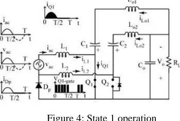
Stage1: In this stage Q1 is turned on. The circuit operation is shown in figure 4. The current VC1 will flow through the switch and hence Dp is forward biased. The diode D01 is reverse biased by reverse voltage (Vac + V0). D02 is reverse biased by output voltage V0. The current through inductors iL1 and iL01 increases linearly with input voltage. Current through inductor iL02 is zero due to constant voltage across C2. The inductor currents iL1 and iL01 are
diLn/dt =Vac/Ln; n = 1; 01 (1)
The peak current through the active switch Q1 is given by
IQ1;pk = (Vm *D1 *Ts)/Le (2)
where Vm is the peak amplitude of the input voltage Vac, D1 is the switch duty cycle, and Le is the parallel combination of inductors L1 and L01 .
ISSN (Print) : 2320 – 3765 ISSN (Online): 2278 – 8875
I
nternational
J
ournal of
A
dvanced
R
esearch in
E
lectrical,
E
lectronics and
I
nstrumentation
E
ngineering
(An ISO 3297: 2007 Certified Organization)
Vol. 4, Issue 5, May 2015
capacitor. This stage ends when Q1 is turned on.
II. OUTPUT REGULATION USING FUZZY CONTROLLER
Figure 8: Basic output voltage regulation loop
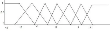
Basic output voltage regulation loop is shown in figure 8. The output voltage can be controlled using closed loop control. A fuzzy control system is a control system based on fuzzy logic which is a mathematical system that analyzes analog input values in terms of logical variables that take on continuous values between 0 and 1 There are three steps for a fuzzy control- Fuzzification, Rule base, defuzzification. The fuzzy controller has two inputs, the error and change in error. Fuzzification is the first step in the fuzzy control.[13-14] Here the membership functions are designed for the input. The process of converting a crisp input value to a fuzzy value is called fuzzification. Seven membership functions are taken with trapezoidal shape.
Seven fuzzy levels or sets are chosen for error (e), change in error (_e) and the output.
1)NL-Negative Large 2)NM-Negative Medium 3)NS-Negative Small 4)ZE-Zero Equal
Second step is to provide the rule controlling the working of a Fuzzy system. Fuzzy control rules are obtained from the analysis of the system behavior. Depending on the operating conditions different control laws can be made and this will improve the performance of the system. The fuzzy rules are based on the following criteria
1. When the output of the converter is far below the set point, the change of duty ratio must be large so as to bring the output to the set point quickly.
2.When the output of the converter is approaching the set point, a small change of duty ratio is necessary.
3. When the output of the converter is near the set point and is approaching it rapidly, the duty ratio must be kept constant so as to prevent overshoot.
Membership functions for error, change in error and output is shown in figures 9, 10, 11 respectively [12].
ISSN (Print) : 2320 – 3765 ISSN (Online): 2278 – 8875
I
nternational
J
ournal of
A
dvanced
R
esearch in
E
lectrical,
E
lectronics and
I
nstrumentation
E
ngineering
(An ISO 3297: 2007 Certified Organization)
Vol. 4, Issue 5, May 2015
Figure 11: Membership function for output
< Ke_crit_max, the converter operates in both modes: CCM near the peak value of the input line voltage and DCM near the zero crossing of the input line voltage.
V. SIMULATED PERFORMANCE
The circuit is simulated using MATLAB in Open loop mode and closed loop mode. PI controller and Fuzzy logic controller is employed to control the circuit. The parameters taken for the simulation are
1)RMS input voltage: 230V
2)Supply frequency: 50HZ
The input voltage and current waveform for the bridgeless cuk rectifier is shown in figure 12. The input current is tracking the input voltage.
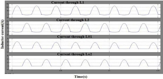
The THD obtained is 25%. The inductor current waveforms are shown in figure 13. Current through Diode Dp and Dn is shown in figure 14. The output voltage is shown in figure 15. Output voltage waveform is constant at 48V. The output voltage regulation is done using Fuzzy controller. The output voltage for fuzzy controller is shown in the figure 16. The output voltage remains constant at 400V which is the reference voltage. So the controller is tracking the reference voltage.
Figure 13: Inductor current waveforms in open loop mode
VI. CONCLUSION
ISSN (Print) : 2320 – 3765 ISSN (Online): 2278 – 8875
I
nternational
J
ournal of
A
dvanced
R
esearch in
E
lectrical,
E
lectronics and
I
nstrumentation
E
ngineering
(An ISO 3297: 2007 Certified Organization)
Vol. 4, Issue 5, May 2015
[1] Abbas A. Fardoun, Esam H. Ismail, Ahmad J. Sabzali and Mustafa A. Al-Saffar, “New Efficient Bridgeless CUK Rectifiers for PFC Applications ” IEEE transactions on power electronics vol. 27, no. 7, july 2012.
[2] Sukumaran V.G., Bharadwaj N., "Ceramics in dental applications", Trends in Biomaterials and Artificial Organs, ISSN : 0971-1198, 20(1) (2006) pp.7-11.
[3] A. Sabzali, E. H. Ismail, M. Al-Saffar, and A. Fardoun, “New bridgeless DCM sepic and CUK PFC rectifiers with low conduction and switching losses ”, IEEE Trans. Ind. Appl, vol. 47, no. 2, pp. 873881, Mar./Apr. 2011.
[4] Selva Kumar S., Ram Krishna Rao M., Balasubramanian M.P., "Chemopreventive effects of Indigofera aspalathoides on 20-methylcholanthrene induced fibrosarcoma in rats", International Journal of Cancer Research, ISSN : ISSN: 1811-9727, 7(2) (2011) pp.144-151. [5] B. Lu, R. Brown, and M. Soldano, “Bridgeless PFC implementation using one cycle control technique ”, Proc. IEEE Appl. Power Electron. Conf.,Mar. 2005, pp. 812817.
[6]Menon R., Kiran C.M., "Concomitant presentation of alopecia areata in siblings: A rare occurrence", International Journal of Trichology, ISSN : 0974-7753, 4(2) (2012) pp.86-88.
[7]Y. Jang and M. M. Jovanovic,“Bridgeless high-power-factor buck converter”, IEEE Trans. Power Electron.,vol. 26, no. 2, pp. 602611, Feb. 2011. [8]Rayen R., Hariharan V.S., Elavazhagan N., Kamalendran N., Varadarajan R., "Dental management of hemophiliac child under general anesthesia", Journal of Indian Society of Pedodontics and Preventive Dentistry, ISSN : 0970-4388, 29(1) (2011) pp.74-79
[9]K. Periyasamy, “Power Factor Correction Based On Fuzzy Logic Controller With Average Current-Mode For DC-DC Boost Converter”, (IJERA) ISSN: 2248-9622, Vol. 2, Issue 5, September- October 2012, pp.771-777.
[10]Shanthi B., Revathy C., Devi A.J.M., Subhashree, "Effect of iron deficiency on glycation of haemoglobin in nondiabetics", Journal of Clinical and Diagnostic Research, ISSN : 0973 - 709X, 7(1) (2013) pp.15-17.
[11]M. R. Sahid, A. H. M. Yatim, Taufik Taufik, San Luis Obispo “A New AC-DC Converter Using Bridgeless SEPIC ” IEEE transactions, 978-1-4244-5226-2/10/.
[12]L. Huber, Y. Jang, and M. Jovanovic “A Performance evaluation of bridgeless PFC boost rectifiers ”, IEEE Trans. Power Electron,vol. 23, no. 3, pp. 13811390, May 2008.
[13]G. Ranganathan, L. Umanand, “New Efficient Bridgeless CUK Rectifiers for PFC Applications ”
[14]D.S.L. Simonetti, J. Sebastiin, F. S. dos Reis and J. Uceda, “Design Criteria for Sepic and CUK Converters as Power Factor Preregulators in Discontinuous Conduction Mode ”
[15] B.Vamsi Krishna, A New Technique for Elimination of Harmonics Using Three Phase Shunt Active Filter, International Journal of Advanced Research in Electrical, Electronics and Instrumentation Engineering, ISSN (Online): 2278 – 8875,pp 5596-5602, Vol. 2, Issue 11, November 2013 [16] P.Thamarai, B.Karthik, ARM Based Automatic Meteorological Data Acquisition System, International Journal of Advanced Research in Electrical, Electronics and Instrumentation Engineering, ISSN (Online): 2278 – 8875,pp 6461-6465, Vol. 2, Issue 12, December 2013
[17] M.Bharathi,Effective Transfer Function Approach for Decentralized Controller,International Journal of Advanced Research in Electrical, Electronics and Instrumentation Engineering, ISSN 2278 - 8875 , pp 21-27, Vol. 1, Issue 1, July 2012.
[18] Vijayan T ,Energy-efficient MAC for Wireless Sensor Networks,International Journal of Advanced Research in Electrical, Electronics and Instrumentation Engineering,ISSN 2278 - 8875, pp 51-57,Vol. 1, Issue 1, July 2012.