ISSN (Print) : 2320 – 3765 ISSN (Online): 2278 – 8875
I
nternational
J
ournal of
A
dvanced
R
esearch in
E
lectrical,
E
lectronics and
I
nstrumentation
E
ngineering
(An ISO 3297: 2007 Certified Organization)
Website: www.ijareeie.com
Vol. 6, Issue 6, June 2017
Design & Analysis of Optimal Maximum
Power Point Tracking Algorithm for PV
systems under Climatic Parameters
Estimation
D.Girija, Dr. G.Sreenivasan
M.Tech, Department of EEE, SRIT, Anantapur, India Prof, Department of EEE, SRIT, Anantapur, India
ABSTRACT: This paper presents a maximum power point tracking (MPPT) method for photovoltaic (PV) systems with reduced hardware setup. It is realized by calculating the instantaneous conductance and the junction conductance of the array. The first one is done using the array voltage and current, whereas the second one, which is a function of the array junction current, is estimated using an adaptive neuro-fuzzy (ANFIS) solar cell model. Knowing the difficulties of measuring solar radiation and cell temperature, since those require two extra sensors that will increase the hardware circuitry and measurement noise, an analytical model is proposed to estimate them with a denoising-based wavelet algorithm. The proposed MPPT technique helps to reduce the hardware setup using only one voltage sensor, while increases the array power efficiency and MPPT response time. The simulation results are provided to validate the MPPT algorithm operation as well as the climatic parameters estimation capabilities.
KEYWORDS:Adaptive neuro-fuzzy (ANFIS) solar cell model, instantaneous conductance, junction conductance, junction current, maximum power point tracking (MPPT), photovoltaic (PV) system.
I. INTRODUCTION
Rapid depletion of fossil fuel reserves, ever increasing energy demand and concerns over climate change motivate power generation from renewable energy sources. Solar photovoltaic (PV) and wind have emerged as popular energy sources due to their ecofriendly nature and cost effectiveness. However, these sources are intermittent in nature. Hence, it is a challenge to supply stable and continuous power using these sources. This can be addressed by efficiently integrating with energy storage elements. In order to overcome the undesired effects such as low conversion efficiency on output power of PV and draw maximum power, well known “maximum power point tracking(MPPT)” is used through a particular control of a converter. Many methods have been proposed to extract maximum power from PV module, which can be classified according to convergence speed , implementation complexity ,periodic tuning ,sensed parameters.
ISSN (Print) : 2320 – 3765 ISSN (Online): 2278 – 8875
I
nternational
J
ournal of
A
dvanced
R
esearch in
E
lectrical,
E
lectronics and
I
nstrumentation
E
ngineering
(An ISO 3297: 2007 Certified Organization)
Website: www.ijareeie.com
Vol. 6, Issue 6, June 2017
Another technique is fuzzy logic (FL) based which have advantages on working with imprecise inputs. It is good in handling nonlinearity and does not require accurate mathematical model. Combination of NN and FL seems to be more attractive since if associates the learning capability of ANN with the ability of the FL to train inaccurate data, which makes it suitable for PV applications.
This paper provides an efficient Grid connected PV system with MPPT method with reduced components. It computes the instantaneous and junction array conductance. The first one is done using the array current and voltage, whereas the second one uses the array junction current, which is estimated using ANFIS cell model. Still, it requires information on the climatic parameters. Hence, it is proposed ANFIS control as an analytical model with a denoising based wavelet algorithm to estimate them, which helps reducing the hardware using only one voltage sensor. The simulation results are provided to validate the proposed ANFIS - PV based MPPT scheme capabilities. This paper is organized as follows: Section II provides an overview of modeling of PV system. Section III explains PV system with proposed MPPT technique and grid connected PV system is given by Section IV. The simulation results based on MATLAB are presented in Section V. Section VI gives conclusion.
II. MODELING OF PV MODULE
The schematic diagram of a three-phase grid-connected PV system which is main focus of this paper is shown in Fig. 1. The system consists of a PV array, a DC link capacitor C, a three-phase inverter, a filter inductor L and
connected to the grid with line voltages. In this paper, the main aim is to control the voltage Vdc across the capacitor C
and to make the input current in phase with grid voltage for unity power factor by means of appropriate control signals through the switches of the inverter. The mathematical model of PV system is presented with a solar cell which is basically a p-n semiconductor junction. When exposed to light, a dc current is generated which varies linearly with solar irradiance. Fig. 2 shows an equivalent circuit diagram of the PV cell which consists of single diode connected in
parallel with a light generated current source IL. RS and RSh represent the series and shunt resistance of solar cell.
Usually the value of RSh is very large and that of RS is very small, so this can be neglected to simplify the analysis.
(i)The diode current ION can be written as:
= ( + ) −1 (1)
Where, Is is the saturation current, α=q/AKTCin which q is electron charge (1.6 * 10-19 C), K is the boltzmann constant
(1.38 * 10-23 JK-1), Tc is the cell temperature in the standard test condition (STC), A is the ideal factor of cell dependent
on PV technology whose value is in between 1 and 5,VPV and IPV are voltage and current generated by PV cells. The
output voltage VPV considered as voltage source C in this paper i.e. Vdc.
(ii) The output current (IPV) generated by PV cell can be written as;
= − ( + ) −1 − + (2)
Where, IL is light generated current that depends on solar irradiance which can be written as follows:
= + −
1000 (3)
Where, ISCis cell short circuit current, Ki is short circuit current temperature coefficient, Tref is the cell reference
ISSN (Print) : 2320 – 3765 ISSN (Online): 2278 – 8875
I
nternational
J
ournal of
A
dvanced
R
esearch in
E
lectrical,
E
lectronics and
I
nstrumentation
E
ngineering
(An ISO 3297: 2007 Certified Organization)
Website: www.ijareeie.com
Vol. 6, Issue 6, June 2017
Fig. 1.Block diagram of the PV system.
Fig. 2. Equivalent circuit diagram of PV cell
(iii)The module saturation current Is varies with the cell temperature according to the following equation:
= 1 − 1 (4)
Where, IRS is the reverse saturation current at a reference temperature and solar radiation, Eg is the band gap energy of
the semiconductor used in the cell.
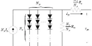
(iv)The output power of single solar cell is very less and it cannot be used for almost any application. So in order to increase the capability of the overall PV systems, a PV module is formed by arranging number of PV cells together and encapsulated with glass, plastic, and other transparent materials to protect from harsh environment. Then the solar cells are connected in series and parallel configuration to form solar modules and arrays.Fig.3 shows an electrical equivalent circuit diagram of a PV array.
ISSN (Print) : 2320 – 3765 ISSN (Online): 2278 – 8875
I
nternational
J
ournal of
A
dvanced
R
esearch in
E
lectrical,
E
lectronics and
I
nstrumentation
E
ngineering
(An ISO 3297: 2007 Certified Organization)
Website: www.ijareeie.com
Vol. 6, Issue 6, June 2017
III. PROPOSED MPPT TECHNIQUE USING ANFIS
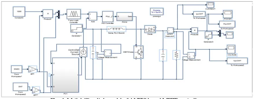
In this paper a new method is adapted for tracking the maximum power point i.e. using an Adaptive Neuro Fuzzy Inference system (ANFIS) which is described in detail in this section. The Matlab/Simulink model of ANFIS based MPPT controllers as shown in the Fig. 4.This model requires two input training data sets which are taken as irradiance level and operating temperature of PV module. Using these data sets the ANFIS reference model gives out the crisp value of maximum available power from the PV module at a specific temperature and irradiance level. This tool enables the construction of a Fuzzy Inference System (FIS) whose membership function parameters are tuned using specific algorithm. According to figure the input data is same for both ANFIS and PV module. The actual output power of PV module is calculated using multiplication algorithm of operating voltage and current and this calculation has been done at same level of temperature and irradiance of ANFIS. The oscillations produced at the output voltage, current and power can be reduced by denoised temperature and irradiance values as inputs, which are formed by using wavelet algorithm.
Fig. 4. Matlab/Simulink model of ANFIS based MPPT controller.
The two powers from PV module and ANFIS are compared and the obtained error is given to a proportional integral(PI) controller, which will generate control signals and this signals are given to PWM generator.Then PWM signals are generated by comparing high frequency carrier signals to reference modulating (or) control signals.The
frequency of carrier signal used is 50KHZ.These PWM signals are given to the DC-DC converter, that is used to control
the duty cycle and in order to adjust the operation point of PV module.
Tuning of ANFIS using Matlab/Simulink can be done by tuning the parameters of a sugeno-type fuzzy
inference system. The training data sets for this can be taken as, the operating temperature varied from 15oC to 65oC in
a step of 5oC and the solar irradiance level is varied from 100W/m2 to 1000W/m2 in a step of 50 W/m2.From this 209
ISSN (Print) : 2320 – 3765 ISSN (Online): 2278 – 8875
I
nternational
J
ournal of
A
dvanced
R
esearch in
E
lectrical,
E
lectronics and
I
nstrumentation
E
ngineering
(An ISO 3297: 2007 Certified Organization)
Website: www.ijareeie.com
Vol. 6, Issue 6, June 2017
Fig. 5. Output from fuzzy rules for specific value of temperature and irradiance.
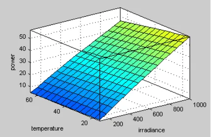
Fig. 6. Surface between two inputs (temperature and irradiance) and one output (maximum power).
FIS system consists of nine rules that are derived from six input membership function which can be formed by two inputs (operating temperature and irradiance level), one output(maximum power) and three membership function for each input. These rules are derived according to the mapping of this inputs and output, so as to produce maximum output power for a specific value of inputs, as shown in Fig. 5. The surface generated by ANFIS is a 3-dimensional plot between temperature, irradiance level and maximum power which is shown in Fig. 6.
IV. SIMULATION RESULTS AND DISCUSSION
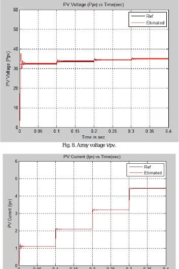
Simulations were done using a PV array built of two mono crystalline 80−W modules (Figs. 1 and 2). To
examine the performance of the proposed MPPT algorithm by means of MATLAB/Simulink, we simulated, in a short
time period of 0.4 s, three step variations in solar radiation (250, 500, 750, and 1000W/m2) with a constant cell
temperature Tc = 25◦C. The resulting array operating voltage and current are shown in Figs. 8 and 9.
We can notice that the array voltage and current track significantly their corresponding references, which means that the array is operating at its maximum power. This can be confirmed by observing its power, which is following precisely the corresponding MPP (Fig. 8). The tracking capability of the algorithm under varying solar radiation is shown in Fig. 9. It is shown in Fig. 11 that, due to the first radiation value, the voltage varies through a
ISSN (Print) : 2320 – 3765 ISSN (Online): 2278 – 8875
I
nternational
J
ournal of
A
dvanced
R
esearch in
E
lectrical,
E
lectronics and
I
nstrumentation
E
ngineering
(An ISO 3297: 2007 Certified Organization)
Website: www.ijareeie.com
Vol. 6, Issue 6, June 2017
Fig. 8. Array voltage Vpv.
ISSN (Print) : 2320 – 3765 ISSN (Online): 2278 – 8875
I
nternational
J
ournal of
A
dvanced
R
esearch in
E
lectrical,
E
lectronics and
I
nstrumentation
E
ngineering
(An ISO 3297: 2007 Certified Organization)
Website: www.ijareeie.com
Vol. 6, Issue 6, June 2017
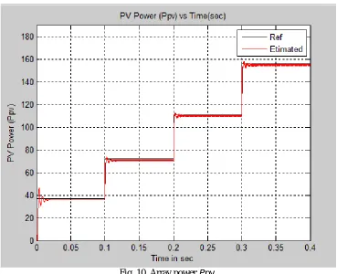
Fig. 10. Array power Ppv.
The simulation results presented in Figs. 8–13 show obviously that the developed algorithm ensures the maximum power operation of the PV array. Its estimated power follows the maximum power under very fast varying solar radiation with a very good precision. The steady-state error is shown in Table I.
TABLE I
ARRAY POWER ESTIMATION ERROR
The mean MPPT error through the entire solar radiation range is found to be around 1.75%, which is very
reasonable. Moreover, the radiation variations are done through a very short period of time (t = 0.4 s). Therefore, it can
ISSN (Print) : 2320 – 3765 ISSN (Online): 2278 – 8875
I
nternational
J
ournal of
A
dvanced
R
esearch in
E
lectrical,
E
lectronics and
I
nstrumentation
E
ngineering
(An ISO 3297: 2007 Certified Organization)
Website: www.ijareeie.com
Vol. 6, Issue 6, June 2017
method under varying solar radiation. The Simulation results exhibit a mean MPPT efficiency error of 2% with a response time of 1.7 ms, which ensures that the developed technique can extract accurately the maximum power from a PV array with a very low response time, which makes its operation optimal with reduced hardware.
REFERENCES
[1] E. Koutroulis, K. Kalaitzakis, and N. C. Voulgaris, “Development of a microcontroller-based, photovoltaic maximum power point tracking control system,” IEEE Trans. Power Electron., vol. 16, no. 1, pp. 46–54, Jan. 2001.
[2]Ravinder kumar kharb,S.L.Shimi,S.Chatterji,Md.Fahim Ansari, “Modeling of solar PV module and maximum power point tracking using ANFIS,” Renewable and Sustainable Energy Review 33(2014) 602-612.
[3]A.M.Zaki,S.I.Amer,M.Mostafa,”Maximum Power Point Tracking for PV System Using Advanced Neural Networks Technique”,IJETAE,vol 2,issue 12,pp.58-63,Dec-2012.
[4]M.Balaji Naik,Dr.P.Sujatha,”Adaptive Fuzzy and Neuro-Fuzzy Inference Controller Based MPPT for PV sytems”,IRJET,vol 2,issue 8,pp.693-701,Nov-2015.
[5]Jin-Woo Jung,Nga Thi-Thuy Vu,Dong Quang Dang,Ton Duc Do,”A Three-Phase Inverter for a Standalone Distributed Generation System:Adaptive Voltage Control Design and Stability Analysis”,IEEE Trans.Energy Conversion,vol.29,no.1,pp.46-56,March.2014.
[6]Quoc-Nam Trinch,Hong-Hee Lee,”An Enhanced Grid Current Compensator for Grid-Connected Distributed Generation Under Nonlinear Loads and Grid Voltage Distortions”,IEEE trans,Industrial Electronics,vol.61,no.12,pp.6528-6537,Dec 2014.
[7]Zeng Liu,Jinjun Liu,Yalin Zhao,”A Unified Control Strategy for Three-Phase Inverter in Distributed Generation”,IEEE Trans.Power Electronics,Vol.29.No.3,pp.1176-1191,March 2014.
[8] T. Esram and P. L. Chapman,“Comparison of photovoltaic array maximum power point tracking techniques,” IEEE Trans. Energy Conversion., vol. 22, no. 2, pp. 439–449, Jun. 2007.
[9] A. Pandey, N. Dasgupta, and A. K. Mukerjee, “High-performance algorithms for drift avoidance and fast tracking in solar MPPT system,” IEEE Trans. Energy Convers., vol. 23, no. 2, pp. 681–689, Jun. 2008.
[10] Hui Zhang, Hongwei Zhou, Jing Ren, Weizeng Liu, Shaohua Ruan and Yongjun Gao, “Three-Phase Grid-Connected Photovoltaic System with SVPWM Current Controller”, Power Electronics and Motion Control Conference, IPEMC '09. IEEE 6th International, pp 2161- 2164, 2009. [11] El Fadil, H. and Giri, F. “Climatic sensorless maximum power point tracking in PV generation systems”. Control Engineering Practice, Vol. 19, N.5, pp. 513–521, May 2011.
BIOGRAPHY
Ms.D.Girija has pursuing her Master of Technology in Power Systems, EEE Department, SRIT, Ananthapur, and Andhra Pradesh, India.