*Corresponding author: [email protected]
2017 UTHM Publisher. All right reserved. penerbit.uthm.edu.my/ojs/index.php/ijie
29
Experiment Tests on Single Phase Inverter Using
Raspberry Pi
Shamsul Aizam Zulkifli
1*, Suriana Salimim
1, Siti Aishah Abd Halim
1,
Mohammad Zulfikar Zahid
1, Siti NurulHuda Razali
1, Nor Aishah Johary
11Department of Electrical Power Engineering, Faculty of Electrical and Electronics Engineering
Universiti Tun Hussein Onn Malaysia, 86400 Parit Raja, Batu Pahat, Johor, 86400, MALAYSIA
Received 13 March 2017; accepted 17 September 2017, available online 18 September 2017
1.
Introduction
Inverter is widely used in industrial application such as for DC power source utilization, electric motor speed control and for generating an AC source from a DC source [1]. Therefore, the input voltage, output voltage or frequency, and overall power handling are depended on the design of the specific device or converter circuitry. The output of inverter can be varied by changing the input of the DC voltage or by changing the inverter gain (D) of output-input ratio.
Inverter is also known as a device that will receive a fixed voltage DC as in Voltage Source Inverter (VSI) and then converts it to variable frequency or variable magnitude AC at the output [2,3,4]. This conversion source can be done by using a power electronics device such as Metal Oxide Semiconductor Field Effect Transistor (MOSFET) as a switching device and it must be controlled by a microcontroller.
Nowadays, with the new generation of microcontrollers which has ability to generate high frequency switching, but with minimum cost, has been available in the market and it is affordable to be purchased by the student. Here, comes the Arduino, Raspberry Pi (RPi) and etc. in the market [4]. These microcontrollers have a new feature, where it can be integrated with the MATLAB-simulink blocks in order for designing the
controller. For this case, it gives an advantage to the student where, they able to understand the concepts of controller in power converters without needs to develop any cross coding algorithm for the switching signals [4,5,6] of the converters.
Due to these advantages, two sets tests have been setup and tested for this project by using the RPi and Arduino. The first experiment is to test, a six steps output inverter voltage generation using RPi microcontroller with the voltage feedback sensor. The signal that will be generated is based to the six steps algorithm that has been created in MATLAB-Simulink blocks without any coding code been applied. This test is conducted because, to observe the signal of the inverter output to behave as six levels output. The second experiment has been conducted to generate a square output inverter with voltage feedback, where the modelling of the inverter controller is developed in the software based on inverter state space mathematical model. For both tests, the RPi has been combined with the Arduino as to be an analog to digital converter (ADC) interface.
Figures 1 shows, the block diagram for the first and second experiments. Both, will start with the MATLAB-Simulink [7] software that will link with the RPi and Arduino boards. This is when the Pulse Width Modulation (PWM) switching pattern is created from the RPi before Abstract: This project is about to develop a single phase inverter that is used to understand the concept of inverter voltage output control using Raspberry Pi as the microcontroller. The medium of communications between the Raspberry Pi and the MATLAB Simulink software is necessary while the Arduino is used as an analog to digital converter for the voltage control feedback. The important of this project is to use the low cost microcontrollers which are the Raspberry Pi and Arduino to generate a suitable PWM switching signal to the inverter based on the instruction that been developed in the MATLAB-Simulink blocks without using any programming framework. This inverter has been tested when the mathematical equation blocks diagram and the controllers have been downloaded to the microcontrollers. At the end, the results show, the selected microcontrollers can be used for generating the PWM signal and also to be as an ADC converter for closed loop voltage operation that will be good to undergraduate student for understanding the concept of microcontroller process use in power converters.
30
been injected to the single phase inverter. On the converter side, the output voltage will be measured by the voltage sensor and be used as feedback to create a closed loop control for the inverter.
Fig.1 Block Diagram of the Project.
2
Inverter module
In this section, two types of the inverter model will be discussed in order to understand the operation of RPi generation signal based on the switching pattern algorithm and mathematical control modelling of the inverter.
2.1
Switching inverter mechanism pattern
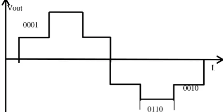
The switching inverter mechanism pattern is used to create a six steps pulse output at the inverter output. The advantage of having six steps output is where the output voltage magnitude of the inverter can be increased to be more from the inverter DC input. In general, this application looks like a multilevel inverter but it only uses single phase inverter as the hardware.Those steps can be created based on the switching pattern given in Table 1. Based on it, at least 1 switch must ‘on’ at one logic time only. At the end, the complete expected output voltage cycle from the inverter is shown in Figure 2. This switching logic will be designed in the MATLAB- Simulink blocks and then been downloaded to the RPi. The advantage of using this method is because[7], the MATLAB library is easy to be used and applied due to updated version and the resource is free to be used.
Table 1: Design Switching Pattern Voltage
Supply (V)
S1 S2 S3 S4
+5Vdc 0 0 0 1
1 0 0 1
0 0 0 1
-5Vdc 0 0 1 0
0 1 1 0
0 0 1 0
Fig. 2 Expected Result of Six Pulses Output Inverter Waveform.
2.2 Mathematical model of the inverter
The inverter mathematical model is based on average state space model for inverter circuit diagram from input to output side is been discussed in this part. It makes the mathematical modelling can easily been modelled for designing the controller rather than the ordinary model [4,5,6]. Therefore, the outputs from mathematical modelling are more accurate and reliable to be used in RPi application.However, the first step is to model the inverter in mathematical model based on an average steady state equations [8]. It helps the authors to ignore the switching operation of the MOSFET. Figure 3 shows the model of the inverter for mathematical modelling.
Vdc Load S3 INVERTER (AVERAGE STATE SPACE)
jωL
VL
VA
i
Fig.3 Average PWM Inverter Model.
From Figure 3, the equations for inverter switching pattern when the D is used at the converter is described by equations,
DVdc = VL + Va DVdc = L
δ
δt𝑖 ++ Va [1]
where D, Vdc, VL, Va, i, L are duty cycle for average state model, inverter input voltage, inverter output voltage, load voltage, output current, inductor. Therefore, after the dq transformation equations [1] for direct and quadrate (d,q) parameters, the new equation can be shown as,
[𝐷𝐷𝑑
𝑞] Vdc = L [[
0 −𝜔 𝜔 0 ] [
𝑖𝑑 𝑖𝑞] + 𝛿 𝛿𝑡 [ 𝑖𝑑 𝑖𝑞]] + [ 𝑉𝑑
𝑉𝑞] [2]
t
0001
0110
31
where,
DdVdc = - Lωiq + L
𝛿
𝛿𝑡𝑖𝑑 + Vd
DqVdc = Lωid + L
𝛿
𝛿𝑡𝑖𝑞 + Vq
Both equations (1,2) show the response of switching pattern to the inverter and it can be rearranged by,
Vd = Lωiq - L
𝛿
𝛿𝑡𝑖𝑑 + DdVdc [3]
Vq = - Lωid - L
𝛿
𝛿𝑡𝑖𝑞 + DqVdc [4]
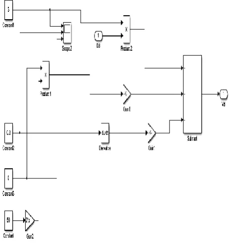
Thus, based on equations [3, 4], the MATLAB- Simulink blocks diagram can be created and been shown in Figure 4 for controlling proposed.
Fig.4 Block Diagram of mathematical modelling of the inverter.
The output of this model will generate the reference signal for PWM operation. This reference signal generates based on the duty cycle of the inverter which is collected from the feedback of the inverter output voltage.
3.
Results and Analysis
The hardware setup has been developed and tested in Power Electronics Laboratory, Universiti Tun Hussein Onn Malaysia. The same setup arrangement has been used for both tests in order to see the performances of the inverter response based in switching pattern and state space control model. At the moment, the problem on the RPi is where, the module library does not have the analog input feedback block. Due to this limitation, the Arduino has been used to be as ADC converter for changing the continuous to discrete signal before it can be feed to the RPi.
Fig.5 Complete Hardware Setup.
Figure 5 shows the overall setup of the hardware part of this project. It consists of RPi, the gate drivers for driving the single phase inverter, the ADC converter for voltage feedback purpose and a voltage divider to match the input signal required by the RPi from the Arduino output.
3.1
Six-step pulse inverter test
For the first test, the hardware has been tested on the open loop condition, without the Arduino and a voltage sensor as a feedback. The switching logic is generated from the MATLAB-Simulink environment which is followed from Table 1. Those switching pattern will be downloaded to the RPi and the result is shown in Figure 6 at the inverter output.
Fig. 6 Output Voltage Open Loop System.
30
Fig. 7 Closed loop voltage feedback.
Figure 7 shows the inverter output voltage result when the closed loop feedback is applied to the system with the same switching pattern given in Table 1. The same input applied to the open loop analysis is applied again and shows the output voltage is increased to almost 10V. However, this signal has shown the problem due to the switching process feedback. After several troubleshooting,
the authors have identified the problem is coming from the ADC and from phase shifted block that do not to sensitive to the discrete configuration on the Arduino. This problem will be addressed and solved in next paper such as to use high resolution of voltage sensor sampling.
3.2 Mathematical model inverter analysis
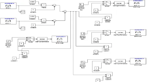
The second test is conducted when the voltage feedback mechanism is applied and it can be referred to Figure 8 blocks diagram. This feedback will respond if the digital signal is been the input to the RPi. The detail how this signal generates from the Arduino is not been explained in this paper. When this signal enter to the RPi, the DAC will be used to change back to analog signal for PWM process based on the mathematical modelling. The overall Simulink block diagram for this operation is shown in Figure 8 where on the left side is the input source while on the right side as the output source to the microcontroller.Fig. 8Block diagram of closed loop system
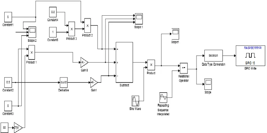
The same hardware setup has been applied again to this second experiment. The block diagram which is shown in Figure 4 is changed to Figure 9. The additional blocks are the PWM generation with the interface of the RPi digital output block and the digital input.
The results for these analyses are shown in Figures 10,11 and 12. Figure 10 shows the output of the RPi in terms of duty cycle on voltage feedback controlled by state space model. It is when, by changing the duty cycle, the output magnitude of the inverter can be changed. This is
due to the changes which accordingly follow to duty cycle pattern. This pattern is look liked the PWM signal due to the injected sinusoidal waveform from Figure 8 to the PWM output generation. This test has been conducted in open loop mode in order to see the performance of the controller switching
Meanwhile, result in Figure 11 is collected when the closed loop feedback is applied. It is where the Arduino is taking place as an ADC process. It shows that, the pattern of the PWM generation is able to be generated when the
31
voltage sensor is applied to the inverter output load. Figure 12 shows the inverter output when a load is connected to Figure 5. It shows that, the inverter is able to generate the AC output of 5Vac when a 5VDC input source is applied. It
indicates, the state space model is working for controlling the voltage of the inverter output. Therefore those microcontrollers can be used as controller interfacing between the controller with the hardware part.
Fig 9 : Block diagram of control strategies to the Arduino.
Fig 10. Open loop test on D with control Fig 11. Voltage feedback test on D with control
*Corresponding author: [email protected]
2017 UTHM Publisher. All right reserved. penerbit.uthm.edu.my/ojs/index.php/ijie
29
Fig.12 Inverter Output voltage.
4.
Conclusion
As a conclusion, this project is able to test the RPi with the inverter as the converter when the switching pattern of the controller can be changed easily due to flexibility of the MATLAB communication to the RPi. Its also explained that, the MATLAB-Simulink blocks library is easily to use either in pattern logic design or mathematical equations of the converter for control process respond. At the end, these criterions have helped the undergraduate student to understand the concept of control theory for controlling a power converter. It also is a good tool for an education training that only required a very minimum cost microcontroller for specific converter application that can be learnt easily.
5.
Acknowledgement
Authors gratefully acknowledge the support of Universiti Tun Hussein Onn Malaysia and Advanced Control for Power Converters Group, FKEE, UTHM to undertake this research activity.
References
[1] Bin Lu, Xin Wu, Hernan Figueroa, Antonello Monti. (2007). A Low Cost Real Time Hardware- in- the- Loop Testing Approach of Power Electronics Controls. IEEE Transactions On Industrial Electronics, VOL. 54, No. 2, APRIL 2007.
[2] Mohd Abdul Talib Mat Yusof (2012). Development of Inverter Controller for BLDC Motor using PIC16F877A. University Tun Hussein Onn Malaysia, January 2012
[3] MdSaifudaullah Bahrudin, Rosni Abu Kassim (2013) Development of Fire Alarm System using Raspberry Pi and Arduino Uno. University Teknologi MARA, Selangor. International Conference on Electrical, Electronics and System Engineering.
[4] Shamsul Aizam Zulkifli M. N. Hussin, Abdul Salam Saad, “MATLAB-Arduino as a Low Cost Microcontroller for 3 phase inverter” 2014 IEEE Student Conference on Research and Development (SCoRED), 16-17 Dis.2015, Penang, Malaysia.
[5] Shamsul Aizam Zulkifli, Mohd Razali Tomari, Mohd Najib Hussin, Abdul. Salam. Saad, Mohd. Khair. Ab Ghani, Farih Deraman , Nawi Berahim, Abdul Hadi Abdullah, “Application of Robust Control on Arduino Microcontroller Testing in Power Electronics Converters”, Journal of Appiled Mechanics and Material, Vol 785, July 2015.
[6] Shamsul Aizam Zulkifli, Suhairiyanti Mohd Yusof, Ahmad Husaini Hussian, Ahamd Izzat Mod Arifin, Mohd Saiful Najib Ismail@Marzuki, Wan Ahmad Khusairi Wan Chek and Faizul Rizal Mohamed Tazudin “MATLAB-SIMULINK Controller Design For Arduino Target on AC Motor Control Application, Inter. Journ. Of Energy and Power Engineering Research, UMPEDAC, [accepted and will be published in July2015]
[7] Mathworks (MATLAB) Manual, excess on Dec. 2014. www.mathworks.com/hardware-support/arduino matlab.html,
[8] Shamsul Aizam Zulkifli, (2010)" Linear generator models in Simulink," in Proc.of IEEE International Conference on Power and Energy (PECon),2010