International Journal of Research in Engineering and Science (IJRES)
ISSN (Online): 2320-9364, ISSN (Print): 2320-9356
www.ijres.org Volume 4 Issue 5 ǁ May. 2016 ǁ PP. 33-38
Differential Evolution And Disparity Line Utilization Factor
Based Congestion Management Of Power System With Interline
Power Flow Controller
Ms. Sajna Soman , Ms. Rinku Scaria
1Mtech Scholar, 2Assistant Professordepartment Of Electrical And Electronics Engineering Federal Institute
Science And Technology
ABSTRACT:
The restructuring of electric power market has led to complex power transmission congestion problems. Additionally, scheduled power flows in the transmission line, as well as spontaneous power exchanges have also risen sharply in recent years. The usage of transmission line that leads to crossing of the limits results in congestion. In the new competitive electric market, it is now mandatory for the electric utilities to operate in ways that make better use of existing transmission facilities, and in conjunction with maintaining the security, stability, and reliability of the supplied power. Congestion management is one of the important techniques to relieve congestion in transmission system. New transmission lines or FACTS devices on the existing transmission system can eliminate transmission over loading, but FACTS devices are preferred in the modem power systems based on its overall performance. For last two decades researches developed new algorithms and models or power flow and optimal power flow incorporating FACTS devices so that cheap power can be made available to the customers without violating system stability. Thus, application of FACTS controllers is a solution to the problem of efficient congestion management. It is a well-recognized fact that the performance of FACTS devices in a power system mainly depends on its placement and tuning. Out of all FACTS devices, IPFC is considered to be the most flexible, powerful, and versatile as it employs at least two VSCs with a common DC link. Hence, IPFC has the capability of compensating multi-transmission lines. The proper placement of IPFC can improve the transmission line congestion problem to a great extent, as it could comprise of reduction of active power loss, minimization of total voltage deviations. etc. Reduction of loss further reduces line congestion and reduction of voltage deviation ensures power quality.Index Terms—
Congestion, Interline power flow controller (IPFC), Disparity Line Utilization Factor (DLUF), Differential Evolution algorithm (DE), Optimal PlacementI.
INTRODUCTION
Restructuring in the electric power industry has led to the problems of power systems related to power delivery and power quality. The issue of transmission congestion is prominent in deregulated and competitive markets, thus needs an effective management strategy.[1] In the new competitive electric market, it is now mandatory for the electric utilities to operate in ways that make better use of existing transmission facilities, and in conjunction with maintaining the security, stability, and reliability of the supplied power.
FACTS devices are preferred in modern power systems based on the requirement, and are found to deliver good solutions. FACTS devices form a better choice for congestion management. It is a well-recognized fact that the performance of FACTS devices in a power system mainly depends on its placement.[2]An algorithm was proposed for optimal congestion dispatch calculation with UPFC control. A decomposition control method was introduced to solve this optimal power flow problem. Mandala and Gupta [5] proposed a method to determine the optimal location of thyristor controlled series compensators (TCSCs) for congestion management. The optimal location is determined based on real power performance index and also on reduction in total system active power and reactive power losses.
Differential Evolution And Disparity Line Utilization Factor Based Congestion Management Of ...
control variables, and is robust and easy to use[14]. It is also considered as good alternative evolutionary algorithms for power system applications.
Line utilization factor (LUF) is used for determining congestion of a single transmission line. Single-line FACTS devices can be placed on the transmission Single-line with maximum LUF value. However, IPFC is a multiline series FACTS device. In its simplest form it consists of at least two converters placed on two transmission lines with a common bus. The first converter of IPFC can be placed on the line with maximum LUF. However, the placement of the other converter is an issue that becomes more and more complex with increases in system size, number of IPFCs, and the complexity of the IPFC. Hence, LUF is not a sufficient index for obtaining IPFC location[15].
Here, a multi objective optimization is formulated for optimal location of IPFC using differential evolution algorithm. It includes reduction of active power loss, minimization of total voltage deviation. Optimal location of IPFC is the optimal solution of the differential evolution based multi-objective problem formulated. Also, the disparity line utilization factor has been used for the optimal placement of IPFC, as it deals with the placement of second converter of IPFC. LUF gives an estimate of the difference of the percentage of line being used for the power flow. First, all lines connected to the optimal location obtained using DE algorithm are ranked in terms of line congestion. Then, DLUF is calculated for all the lines that share a common bus with the most congested line. The IPFC is placed in the lines with maximum value of DLUF to reduce congestion and power loss in the system. Placement of IPFC for reduction of loss further reduces line congestion. Reduction of voltage deviation ensures power quality. The method under consideration is implemented on an IEEE 7 bus system.
II.
INTERLINE POWER FLOW CONTROLLER
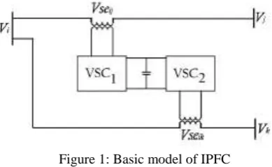
IPFC consists of at least two back-to-back DC-AC converters connected via a common DC link. Vi, Vj , and Vk are complex voltages at buses i, j, and k respectively. Vl =Vl<ϴl (l = i, j, k) and Vl, ϴl are the magnitude and angle of Vl. Vsein is the complex controllable series injected voltage source, which represents the series compensation of the series converter. Vsein is defined as Vsein =Vsein<ϴsein (n = j,k). Vsein and ϴsein are the magnitude and angle of Vsein. The basic model of IPFC, as shown in Fig1 consists of three buses i, j, and k .
Figure 1: Basic model of IPFC
Two transmission lines are connected with the bus i in common. The equivalent circuit of the IPFC with two converters is represented with two series injected voltage sources, as shown in Fig 2. Zsein is the series transformer impedance. Pi and, Qi are the sum of the active and reactive power flows leaving the bus i.
Differential Evolution And Disparity Line Utilization Factor Based Congestion Management Of ...
III.
DIFFERENTIAL EVOLUTION ALGORITHM AND DISPARITY LINE
UTILIZATION FACTOR
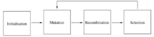
A.Differential Evolution AlgorithmDifferential evolution (DE) is technically population based Evolutionary Algorithm, capable of handling non-differentiable, nonlinear and multi-modal objective functions. DE generates new offspring by forming a trial vector of each parent individual of the population. The population is improved iteratively, by three basic operators: mutation, crossover, and selection. A block diagram of different steps of DE algorithm is given below.
Figure 3: Procedures involved in Differential Evolution
B.Disparity Line Utilization Factor
Line utilization factor (LUF) is an index used for determining the congestion of the transmission lines. It is given by,
(1)
where LUFij is line utilization factor of the line connected to bus i and bus j, is maximum MVA rating of the line between bus i and bus j, and MVAij is actual MVA rating of the line between bus i and bus j. LUF gives an estimate of the percentage of line being utilized and is an efficient method to estimate the congestion in a line. For placement of IPFC, there should be at least two lines connected to a common bus. Therefore, LUF is not suffcient for placement of IPFC. Hence, a new index disparity line utilization factor is proposed for the optimal placement of an IPFC. The index provides an estimate of the difference of the percentage of line being used for the power flow. All the lines are first ranked in descending order of their line utilization factors. The line that is the first rank is considered as the most congested line. DLUF is calculated for the lines connected to the line with highest congestion. All the line pairs connected to the same bus are ranked based on DLUF. The line set that has highest value of DLUF is considered to be the optimal location for IPFC for congestion management. Assuming both lines of same rating,
(2)
where, DLUF(ij)ϴ(ik) is the disparity line utilization factor of the line set ij and ik connected to bus i and bus j, MVAij is the MVA rating of the line between bus I and bus j, MVAmax is the maximum MVA rating of the line, and MVAik is the actual MVA rating of the line between bus i and bus k. An objective function is also formulated to find the optimal location of IPFC, which minimizes the active power losses and total voltage deviations.
IV.
PROBLEM FORMULATION
A.Objective Function
A multi-objective function is formulated as,
(3) Where w1,w2,w3,w4 are the weighting factors
w1+w2=1 w1=w2=0.5 .
1. Reduction of Loss:
The expression for reduction of active power loss,
Differential Evolution And Disparity Line Utilization Factor Based Congestion Management Of ...
where lk is the number of transmission lines, are the voltages at the end buses i and n (n = j, k) , are the voltages at the end buses.
2. Minimization of voltage deviation
To have a good voltage performance, the voltage deviation at each bus must be made as small as possible. The voltage deviation (VD) can be expressed by,
(5)
where Vk is the voltage magnitude at bus k.
B.Equality Constraints
(6)
(7)
C.Inequality Constraints
(8) (9)
D.IPFC Constraints
(10) (11)
V.
RESULTS AND DISCUSSIONS
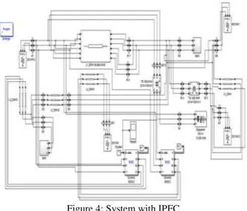
MATLAB codes for DLUF and a modified power flow algorithm for the optimal placement of IPFC was developed and incorporated together for the simulation purposes. To investigate the validation of the technique under consideration, it has been tested on a 7 bus system.
Optimal location of IPFC is the location with higher voltage deviation as well as real power losses, and with maximum DLUF. Hence, IPFC is placed between line sets 1- 2 and 1-3 here.
Figure 4: System with IPFC
Differential Evolution And Disparity Line Utilization Factor Based Congestion Management Of ...
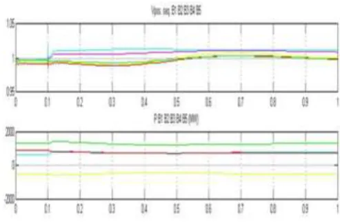
Figure 6: Voltage and active power at different buses before and after ipfc placement
Bus voltage deviation, active power and LUF at the buses and lines to which IPFC is connected has been tabulated.
TABLE 1: VOLTAGE DEVIATION
BUS WITHOUT IPFC WITH IPFC
1 1.009 0.998
2 2.186 2.171
3 0.999 0.987
TABLE 2: ACTIVE POWER
BUS WITHOUT IPFC WITH IPFC
1 612.3 757.9
2 199.5 202.2
3 128.1 130.2
TABLE 3: LINE UTILIZATION FACTOR
LINE SET WITHOUT IPFC WITH IPFC
1-2 0.440 0.433
1-3 0.156 0.150
Results shows that, after the placement of IPFC, the voltage profile and active power at the respective buses were improved. Reduction in LUF value after the placement of IPFC indicates congestion relief, as here, LUF is considered as the index for congestion. Also, optimal placement of IPFC using DE algorithm and DLUF, ensures the effective utilization of the device.
VI.
CONCLUSION
A disparity line utilization factor for the optimal placement of IPFC for congestion management has been used. The IPFC is accordingly placed in the lines with highest DLUF value. It is established that placement of IPFC using DLUF effectively reduces line congestion and power loss. A multi objective function comprising reduction of active power loss and minimization of total voltage deviations are also considered for the optimal placement of IPFC using differential evolution algorithm. The proposed method is implemented for IEEE 7 bus test system.
Differential Evolution And Disparity Line Utilization Factor Based Congestion Management Of ...
[1]. X. P. Zhang and L. Yao, “A vision of electricity network congestion management with FACTS and HVDC”, in The Third International Conference on Electric Utility Deregulation and Restructuring and Power Technologies, IEEE PES, IET, CSEE, Nanjing, China, 2008, pp. 116121.
[2]. M. Gitizadeh and M. Kalantar, “A new approach for congestion management via optimal location of FACTS devices in deregulated power systems”, in The Third International Conference on Electric Utility Deregulation and Restructuring and Power Technologies, IEEE PES, IET, CSEE, Nanjing China, 2008, pp. 15921597.
[3]. F. Qian, G. Tang, and Z. He, “Optimal location and capability of FACTS devices in a power system by means of sensitivity analysis and EEAC”, in The Third International Conference on Electric Utility Deregulation and Restructuring and Power Technologies, IEEE PES IET CSEE, Nanjing China, 2008, pp. 21002104.
[4]. P. Ye, Y. Yang, T. Wang, F. Sun, and H. Zhao, “Decomposition control of UPFC for optimal congestion dispatch”, in The Third International Conference on Electric Utility Deregulation and Restructuring and Power Technologies, IEEE PES, IET, CSEE, Nanjing China, 69 Apr. 2008.
[5]. M. Mandala and C. P. Gupta, “Congestion management by optimal placement of FACTS device”, in PEDES and 2010 Power India, New Delhi, India, 2010, pp. 17.27
[6]. S. S. Reddy, M. S. Kumari, and M. Sydulu, “Congestion management in deregulated power system by optimal choice and allocation of FACTS controllers using multi-objective genetic algorithm”, in Transmission and Distribution Conference and Exposition, IEEE PES, New Orleans, LA, Apr. 2010, pp. 17.
[7]. N. Acharya and N. Mithulananthan, “Locating series FACTS devices for congestion management in deregulated electricity markets”, Electric Power Systems Research, vol. 77, no. 34, pp. 352360, Mar. 2007.
[8]. J. Zhang, “Optimal power flow control for congestion management by interline power flow controller (IPFC)”, in International Conference on Power System Technology 2006, Chongqing, China, 2006, pp. 16.
[9]. K. H. Mohamed, K. S. Rama Rao, and K. N. Md. Hasan, “Application of particle swarm optimization and its variants to interline power flow controllers and optimal power flow”, in 2010 International Conference on Intelligent and Advanced Systems (ICIAS), IEEE, Kuala Lumpur, Malaysia, 2010, pp. 16.
[10]. L. Kirschner, D. Retzmann, and G. Thumm, “Benefits of FACTS for power system enhancement”, in Transmission and Distribution Conference and Exhibition: Asia and Pacific, IEEE/PES, Dalian, China, 2005, pp. 17.
[11]. M. A. Abdel-Moamen, and N. P. Padhy, “Optimal power flow incorporating FACTS devices-bibliography and survey”, in Proceedings of 2003 IEEE PES Transmission and Distribution Conference and Exposition, 2003, pp. 669676.
[12]. N. G. Hingorani and L. Gyugyi, “Understanding FACTS: Concepts and Technology of Flexible AC Transmission System”. New York, NY, USA: IEEE, 2000.
[13]. S. Teerthana, A. Yokoyama, “An optimal power flow control method of power system using interline power flow controller”, in Proceedings of IEEE Region 10 Conference TENCON 2004, Nov. 2004, pp. 343346 28
[14]. R. Storn and K. Price, “Differential evolution, a simple and effcient heuristic for global optimization over continuous spaces”, Journal of Global Optimization, vol. 11, no. 4, pp. 341359, 1997.