82
Enhancement of Implementing Cryptographic Algorithm
in FPGA built-in RFID Tag Using 128 bit AES and 233 bit kP
Multitive Algorithm
Luc Nhu Quynh
1,2, Dang Vu Son
2, Mai Anh Tuan
1,*1
International Training Institute for Materials Science, Hanoi University of Science and Technology, 1 Dai Co Viet, Hanoi, Vietnam
2
Accademy of Cryptography Techniques, 141 Chien Thang, Thanh Xuan, Hanoi, Vietnam
Received 17 April 2017
Revised 22 May 2017; Accepted 15 June 2017
Abstract: Cryptographic application plays an important role in wireless communication, especially, a FPGA built-in RFID tag on UHF band (860-960 MHz). The information safety can be obtained by applying suitable and advanced cryptographic algorithm. This paper simulates the installation and implementation of cryptographic algorithm on a FPGA using Isim software from Xilinx. The result shows that the implementation of 128-bit Advanced Encryption Standard-AES improved considerably the operating speed by 565000 ps for both encryption and decryption process. Similarly, the 233-bit multitive algorithm kP on elliptic curve also enhanced then operating speed at 467661900000 ps.Using above mentioned algorithm, the system maintains the security level meanwhile it does not require very high hardware configuration.
Keywords: Information safety, RFID, FPGA, AES, point multitive algorithm.
1. Introduction
RFID (Radio Frequency Identification) is a technology which uses electromagnetic to identify
target. This technology allows object identification through radio transceiver, from which each target could be traced individually. RFID utilizes a tag and a reader to automatically recognize the object based on distant data storage.
The working mechanism of RFID system is based on the electromagnetic communication, such as electromagnetic transformation between the transponder and the reader. The antenna of the reader creates an electromagnetic field which helps to connect with the antenna of the tag. The current will charge up the capacitor which supply the power for the reader to operate within the circle of antenna’s length and that power will decrease with the distance [1].
_______
Corresponding author. Tel.: 84-0984180146. Email: [email protected]
Security integration in a transmitting system has attracted great attention of scientists and manufacturers due to its potential application in different fields, especially in national security and defense. In an integrated system, RFID is used for identifying the terminal device where the rest (antenna and FPGA) play as information transmission.
The development of cryptographic algorithms on RFID tags are also of scientist worldwide concern. Since the first report of Neal Koblitz and Victor Miller about encryption and decryption algorithm based on elliptic curves, many reports have been published which focus on signing, authentication and implementation of these algorithms on different hadwares [2, 3].
Several groups within Vietnam have also been paying attention to develop such RFID based technology and obtained considerable results [4, 5]. However, none of them reported the implementation of the above-mentioned algorithms in a FPGA chip.
In this work, the implementation of encryption algorithm (AES 128 bit and point multiplication 233 bit) for Spartan6 XC6SLX150T chip will be presented. Algorithm integration to chip has improved the speed of the algorithm on the chip. It’s also supposed that the algorithm may enhance the processing speed of the system by embedding it in both software and firmware of the system.
2. Security module on fpga chip
For security-integrated RFID system, security problems as verification protocol, encryption and decryption and random key can be performed by means of several algorithms like symmetric cryptosystem (AES) or Asymmetric cryptosystem (RSA, ECC) on FPGA. The selected FPGA, implemented in this work, is Spartan6 XC6SLX150T FPGA with package 3FGG900 [6].
2.1. Symmetric Cryptosystem module AES
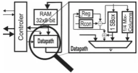
The new Data Encryption Standard (DES) structure named after Dr. Rijndael replaced the old one (first reported in 1974) by National Institute of Standards and Technology (NIST) in 2000. This is a symmetric-key algorithm with three different key lengths to be chosen (128, 192 and 256-bit). This Advanced Encryption Standard (AES) was built based on “addition” and “multiplication” on byte in a finite field [2, 7- 9]. In 128-bit FPGA chip, AES architecture composes four parts [2, 8], figure 1, and includes following operations:
Figure 1. AES module architecture.
Sub-bytes () is a nonlinear operation, and it operates individually on each state byte using a
transformation table (S-box). S-box is inversible and is created from two transformations: Firstly, byte Sij became its inverse with operation (.) in GF (2
8
) field. Element unit {00} is retained. Secondly, the resulting byte is transformed by affine transformation GF (2) following this equation:
'
( 4) mod8 ( 5) mod8 ( 6) mod8 ( 7) mod8
i i i i i i i
b b b b b b c
Shiftrows () implements operation on each rows of the state array. The first-row r = 0 is retained while the remaining row is shifted left with different offsets.
MixColumns () implements operation on each column, which means that each column is
considered as a polynomial of four operators. Columns are considered as a polynomial in GF (28) field and multiplied by modulo (x4+1) with a fixed polynomial a(x).
AddRoundKey (State, RoundKey) is also called as key adder, where a round key is added to the
state by a simple XOR operation.
Symmetric cryptosystem AES includes three basic components: a controller, RAM and datapath.
The controller interfaces with other modules on the tag to exchange information and implementation sequence of 10 round AES. It addresses RAM and creates signal to control datapath. RAM of FPGA chip can store up to 128 state bits and round keys. Therefore 256 bits are arranged as 32 bytes to conform to the 8-bit architecture. 32 byte is the smallest storage configuration available for AES. These states are adjusted and round keys are over-written. Because there is no backup storage for intermediate values store, the controller must ensure that no state byte or key byte is overwritten if they are necessary for encryption. Datapath of AES contains logic combination to calculate the operation SubByte, MixColumn and AddRoundKey. ShiftRow operation is set in the controller of FPGA chip. During SubByte implementation, the controller addresses RAM so that ShiftRow operator is implemented. The largest part of datapath is the S-box used for SubByte operator. There are many options for S-box implementation. S-box combination is implemented by ignoring decryption circuit to adapt with AES encryption. S-box property is pipeline architecture due to register insertion. S-box is used as a pipeline when using 7 XOR gate, …
2.2. Asymmetric cryptosystem module
Elliptic Curve: It is a cubic equation of the form y2 + axy + by = x3 + cx2 +dx +e, where a, b, c, d,
e are real numbers [2, 3, 8, 10, 11]. On E curve, we defined a special addition with O as the infinity point. If a line cuts the E curve at 3 points, then the sum of them equals to infinity point O (O is the element unit in addition).
The addition of two points: A line through two points P, Q cut E at one point R. At point R construction line, perpendicular horizontal axis and cut E at the point R’. Point R’= P + Q.
Multiply point 2P: From the point P, to gradient line of E and cut E in R. At point R construction
line, perpendicular horizontal axis and cut E at the point R’. Point R’= 2P.
Elliptic curve on Galois field: A group E on Galois field Ep(a,b) can be received by computing
x3+ax+b mod p with 0≤ x < p. The constants a, b are non-negative integers and smaller than the prime number p, which satisfies 4a3+27b2 mod p ≠ 0. With each x value, we need to determine whether it is a reduced square. If x is a reduced square then it belongs to the elliptic group, otherwise this point doesn’t belong to Ep(a,b). Addition and multiplication of points can be applied by the algorithm
presented in [2, 3, 8, 10].
Elliptic curve cryptography: In this security system the plaintext M is encrypted into a point PM in
a finite elements set of group Ep(a,b). Firstly we need to choose a generated point G Ep(a,b) such as
the smallest of n satisfy that nG = 0 is a very big primer. Those cryptosystems and protocol often use point multiplication kP algorithm. If point multiplication kP is implemented on hardware, memory and encryption/decryption speed could be optimized.
Security valuation: To break ECC, the computing complication when using S-Pollard method is
3.8x10¹⁰ MIPS-year with key size is 150 bits (this is the number of years required for a computing system with the speed of millions of commands per second). Compare with RSA cryptosystem, a prime factorization which analyze n into product of prime number p and q, with n of length 768 bit the computing compliation is 2x10⁸ MIPS/year, with n of length 1024 bit, the computing complication is 3x10¹¹ year. If RSA key size increases to 2048 bits then it requires 3x10²⁰ MIPS-year, while for ECC the key size of only 234 bits requires 1.6x1028 MIPS-year.
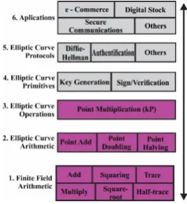
Figure 2 illustrates a 6-layer structure of cryptography based on the elliptic curve. Layer 1 to layer 3 are the mathematical basics for the operation of cryptography. Normally those calculations are designed to embed in chip or stand-alone integrated circuit. Layer 4 and 5 are more flexible, they could be designed to be implemented by hardware or firmware. Integrated hardware is not required for these two layers. Layers 6 is the user applications. Here kP algorithms will be designed based on addition and point multiplication [10, 11]. In this work, ISIM simulation tools of Xilinx was used to design and simulate the cryptographic algorithms.
3. Results and discussion
Symmetric Crypto module for FPGA chip
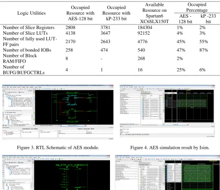
Table 1 shows the resource of the FPGA chip occupied by AES 128-bit encryption algorithm. Figure 3 and 4 illustrate that the simulated algorithm on Spartan6 XC6SLX150T for both encryption and decryption took only 565000 pico second. In comparison with current literature, the algorithm helped to improve strongly the efficiency and speed of the system [8, 12, 13].
The designed AES algorithm in integrated on-chip FPGA, on one hand, improved significantly the speed of encryption and decryption execution of wireless communications and, on the other hand, it strongly maintains the secucirty of the system against the possible attack.
Asymmetric Crypto module for FPGA chip
Table 1. Allocated resrouces for AES and kP on Spartan6 XC6SLX150T
Logic Utilities
Occupied Resource with
AES-128 bit
Occupied Resource with
kP-233 bit
Available Resource on
Spartan6 XC6SLX150T
Occupied Percentage AES
-128 bit
kP -233 bit
Number of Slice Registers 2808 3781 184304 1% 2%
Number of Slice LUTs 4138 3647 92152 4% 3%
Number of fully used
LUT-FF pairs 2170 2643 4776 45% 55%
Number of bonded IOBs 258 474 540 47% 87%
Number of Block
RAM/FIFO 8 - 268 2%
Number of
BUFG/BUFGCTRLs 4 1 16 25% 6%
Figure 3. RTL Schematic of AES module. Figure 4. AES simulation result by Isim.
Figure 5. RTL schematic of kP point multiplication on FPGA chip.
Figure 6. 233-bit kP algorithm simulation result.
The speed-up and resource saving algorithm is the basis for cryptography design, protocol and media applications in wireless network security communication.
4. Conclusion
the resource saving in Spartan6 XC6SLX150T. The results showed that both algorithm improved strongly the execution speed of the chip. The resource saving capability obtained by 233-bit kP point multiplication algorithms does not require a latest technology chip for design and development of the entire sysem. These algorithms also contribute to enhance the integrated-system security that will be application in wireless communication.
Acknowledgements
Colleagues and PhD. Student are acknowledged for their contribution in this work.
References
[1] S. A. Ahson and M. Ilyas. RFID Handbook: Applications, Technology, Security, and Privacy. Taylor & Francis, 2008.
[2] Darrel Hankerson Alfred Menezes Scott Vanstone, “Guide to Elliptic Curve Cryptography”, ISBN 0-387-95273-X ( a l k . paper), (c) 2004 Springer-Verlag New York.
[3] H. ROSEN, “Elliptic Curves Number Theory and Cryptography”, Second Edition, © 2008 by Taylor & Francis Group, LLC, Chapman & Hall/CRC is an imprint of Taylor & Francis Group, an Informa business, International Standard Book Number-13: 978-1-4200-7146-7 (Hardcover), http://www.taylorandfrancis.com
[4] Thuat Nguyen-Tran, Mau Chien Dang, Nhan Ai Tran, Anh Hoang, Dat Son Nguyen, Eric FribourgBlanc, “Contribution on UHF RFID antenna design and tag fabrication”, September 2011, https://www.researchgate.net/publication/220866381
[5] Van Hieu Nguyen, Hong Phuong Phan, Member, IEEE, Manh Ha Hoang, Dat Son Nguyen, Mau Chien Dang, Thuat Nguyen-Tran, Nhan Ai Tran, Anh Hoang, Eric Fribourg-Blanc “Improving Radiation Characteristics of UHF RFID Antennas by Zigzag Structures”, 2011 International Conference on Advanced Technologies for Communications (ATC 2011).
[6] Spartan-6 FPGA data sheet, DS162, DS160 (v2.0) October 25, 2011, http://www.xilinx.com
[7] National Institute of Standards and Technology. (2001, Nov). FIPS-197: Advanced Encryption Standard, Gaithersburg, MD [Online]. Available: http://www.itl.nist. gov/fipspubs/.
[8] P. M. Sandhya, K. Dhanunjaya, “Security-Enabled Near-Field Communication Tag with Flexible Architecture Supporting Asymmetric Cryptography” ISSN 2319-8885, Vol.04, Issue.01, January-2015, Pages:0107-0113, www.ijsetr.com.
[9] EPCglobal Inc. Class-1 Generation-2 UHF RFID protocol for communications at 860 MHz - 960 MHz (version 1.2.0), 2008.
[10] Shuai Liu, Lei Ju, Xiaojun Cai, Zhiping Jia, Zhiyong Zhang, “High Performance FPGA Implementation of Elliptic Curve Cryptography over Binary Fields”, IEEE Xplore: 19 January 2015, ISBN: 978-1-4799-6513-7. [11] Batina, J.Guajardo , T.Kerins, N.Mentens, P.Tuyls, and I.Verbauwhede, “Public-Key Cryptography for
RFID-Tags”, 19-23 March 2007, ISBN: 0-7695-2788-4.
[12] Thomas Plos, Manfred Aigner, Thomas Baier, Martin Feldhofer, Michael Hutter, Thomas Korak, Erich Wenger “Semi-Passive RFID Development Platform for Implementing and Attacking Security Tags”, International Journal of RFID Security and Cryptography (IJRFIDSC), Volume 1, Issue 1, June 2012
[13] Martin Feldhofer, “Securing Passive RFID Tags Using Strong Cryptographic Algorithms”, 4th European Workshop on RFID Systems and Technologies, 10-11 June, 2008, Freiburg, Germany.
[14] Hilal Houssain, Turki F. Al-Somani “Elliptic Curve Cryptoprocessor Implementation on a Nano FPGA: Interesting for Resource-Constrained Devices”, International Journal of RFID Security and Cryptography (IJRFIDSC), Volume 1, Issue 2, December 2012