University of Trento
Giuseppe Abbiati (Ph.D. Student)
DYNAMIC SUBSTRUCTURING OF
COMPLEX HYBRID SYSTEMS BASED ON
TIME-INTEGRATION, MODEL REDUCTION
AND MODEL IDENTIFICATION
TECHNIQUES
Prof. Oreste S. Bursi (Tutor)
University of Trento
Doctorate in Engineering of Civil and Mechanical
Structural Systems - Cycle XXVI
Board of examiners:
Prof. Dionisio P. Bernal
Prof. Michel Destrade
Prof. Oreste S. Bursi
Prof. Andrea G. Calogero
ABSTRACT
Hybrid Simulation with Dynamic Substructuring (HSDS) is a mixed
numerical/-experimental simulation techniques. In detail, HSDS combines a Physical
Sub-structure (PS) -the most critical subpart- with a Numerical SubSub-structure (NS), and
a compliant time integration process calculates the overall dynamic response of
the emulated system. With the objective to circumvent three among major
limita-tions of HSDS, the present thesis offers methodological procedures and algorithms
aimed at: i) emulating a consistent degradation between PSs and NSs via model
updating techniques; ii) handling PSs characterized by several internal DoFs with
a reduced number of interface actuation points; iii) improving the computational
efficiency in the case of complex NSs via partitioned time integrators. An old
re-inforced concrete bridge and a steel piping network for industrial plants are
intro-duced as full-scale structural case studies.
Part of significant results were published on referee journals and proceedings of
international conferences. Part of developed tools was uploaded to theNEESHub
web repository that is a United States web platform for research, collaboration and
education powered by the George E. Brown, Jr. Network for Earthquake
ACKNOLEDGEMENTS
First and foremost, I must thank my family and my girlfriend Gemma for their love
and patience.
To my supervisor, Prof. Oreste Salvatore Bursi, who drove me throughout the
invaluable experience of the doctorate.
To Prof. Rosario Ceravolo, who always stimulated me through constructive
discussions.
To Dr. Pierre Pegon, Dr. Francisco Javier Molina and all the guys of the ELSA
Laboratory of Joint Research Centre of Ispra, for their support and hints.
To the RETRO team and in particular to Dr. Fabrizio Paolacci and Dr. Luigi Di
Sarno, for their precious cooperation.
To the University of Trento for granting me the Ph.D. fellowship to commence this
thesis and to carry out the inherent work.
To the Laboratory and Structures and Material of the University of Trento that
allowed for conducting a significant part of developed experimental activities.
PUBLICATIONS
As a result of the work conducted in this thesis, the following publications have
been produced:
Journal publications
• Ceravolo R., Abbiati G., 2012. Time Domain Identification Of Structures: A Comparative Analysis Of Output-Only Methods - International Journal of
Engineering Mechanics, 139(4).
• Bursi O.S.,Abbiati G., Reza Md.S., 2013. A Novel Hybrid Testing Approach for Piping Systems of Industrial Plants. Special Issue of Smart Structures
and Systems on ”Recent Advances in Real-time Hybrid Simulation” (RTHS)
-In publication.
• Reza Md.S.,Abbiati G., Bursi O.S., Paolacci F., 2013. Seismic performance evaluation of a full-scale industrial piping system at serviceability and ultimate
limit states. Journal of Loss Prevention -Submitted.
• Abbiati G., Ceravolo R., Surace C., 2013. Unbiased time-dependent estima-tors for on-line monitoring of full-scale structures under ambient excitation.
Mechanical Systems and Signal Processing -Under review.
• Abbiati G., Bursi O.S., Di Sarno L., Molina F.J., Paolacci F., Pegon P., 2014. Hybrid simulations of a multi-span RC viaduct with plain bars and sliding
bearings -In preparation.
SCOPUS indexed publications
• Reza M.S.,Abbiati G., Bonelli A., Bursi O.S., 2013. ”Pseudo-dynamic testing of a piping system based on model reduction techniques”. SERIES
Conclud-ing Workshop joint with NEES-US Earthquake EngineerConclud-ing Research
Infras-tructures. JRC Ispra, May 28-30.
• Abbiati G., Bursi O.S., Cazzador E., Mei Z., Paolacci F., Pegon P., 2013. ”Pseudo-dynamic testing with non-linear substructuring of a reinforced
con-crete bridge”. SERIES Concluding Workshop joint with NEES-US
• Paolacci F., Di Sarno L., Pegon P., Molina F. J., Poljansek M., Bursi O.S.,
Abbiati G., Ceravolo R., Erdik M., Deisi R., Mohamad A, 2013. ”Assessment of the seismic behaviour of a retrofitted old R.C. highway bridge through PsD
testing”. SERIES Concluding Workshop joint with NEES-US Earthquake
En-gineering Research Infrastructures JRC Ispra, May 28-30.
• Paolacci F., Di Sarno L., De Risi R.,Abbiati G., Mohamad A., Malena M., Corritore D. 2013. ”Refined and simplified numerical models of an isolated
old highway bridge for PsD testing”. SERIES Concluding Workshop joint with
NEES-US Earthquake Engineering Research Infrastructures JRC Ispra, May
28-30.
NEESHub uploads
Following developed software has been uploaded to the NEESHub (https:
//nees.org/) where is available as open source code:
• simlsrt2 - id #209: Simulink implementation of the LSRT-2 time integration
algorithm.
• stftnlidtool - id #208: Matlab system identification tool based on the Short
Time Fourier Transform (STFT).
• simmgalpha- id #210: Simulink implementations of the Modified
C
ONTENTS1 INTRODUCTION 1
1.1 Hybrid Simulation with dynamic substructuring . . . 1
1.2 Original scientific contributions of the thesis . . . 2
1.3 Structure of the thesis . . . 4
2 HYBRID SIMULATION WITH DYNAMIC SUBSTRUCTURING: STATE-OF-ART OPEN CHALLENGES 7 2.1 Model updating in HSDS . . . 7
2.2 HSDS of PSs characterized by a complex geometry . . . 10
2.3 Partitioned time integrators for continuous testing . . . 11
3 DYNAMIC SUBSTRUCTURING OF THE FIBER-BASED FINITE ELEMENT MODEL OF THE RIO TORTO BRIDGE FOR HYBRID SIMULATION PUR-POSES 15 3.1 Introduction . . . 15
3.2 Description of the case study . . . 16
3.3 The OpenSEES FE Reference Model . . . 22
3.4 Dynamic substructuring of the Rio Torto Bridge for the purpose of hybrid simulation . . . 27
3.4.1 ANSYS linear models of bridge . . . 32
3.4.2 Dynamic substructuring of piers . . . 39
3.4.3 Dynamic substructuring of isolators . . . 45
3.6 Validation of the reduced model of the Rio Torto Bridge in the
iso-lated case . . . 48
3.7 Conclusions . . . 55
4 HYBRID SIMULATION OF THE RIO TORTO BRIDGE 57 4.1 Introduction . . . 57
4.2 Substructuring scheme . . . 58
4.3 Description of scaled physical substructures . . . 62
4.3.1 Scaling of physical piers . . . 63
4.3.2 Scaling of physical FPB isolators . . . 66
4.4 Description of the experimental set-up . . . 66
4.4.1 Experimental set-up of piers . . . 74
4.4.1.1 Displacement measurements . . . 77
4.4.1.2 Photogrammetric measurements . . . 81
4.4.2 Experimental set-up of FPB isolators . . . 81
4.5 Scheduling of experiments and model updating testing procedure . . 86
4.5.1 Characterization of FPB isolators . . . 86
4.5.2 Characterization of piers . . . 88
4.5.3 Hybrid simulation of the Rio Torto Bridge . . . 88
4.5.4 The model updating testing procedure . . . 90
4.6 Nonlinear identification of physical substructures . . . 92
4.6.1 Characterization of piers . . . 94
4.6.2 Characterization of FPB isolators . . . 96
4.7 Model updating of numerical substructures . . . 99
4.8 Results of hybrid simulations . . . 107
4.8.1 The non isolated Rio Torto Bridge . . . 107
4.8.2 The isolated Rio Torto Bridge . . . 117
4.9 Conclusions . . . 119
5 HYBRID SIMULATION OF AN INDUSTRIAL PIPING SYSTEM BASED ON MODEL REDUCTION 123 5.1 Introduction . . . 123
5.2.1 Main characteristics and dimensions . . . 124
5.2.2 Selection of input earthquake loading . . . 125
5.2.3 Characterization of approximated elbow elements . . . 126
5.3 Substructuring and FE modelling . . . 128
5.3.1 ANSYS FE models of the piping system for PDT . . . 130
5.3.2 ANSYS FE models of the piping system for RT . . . 134
5.4 Model reduction techniques applied to the PS . . . 135
5.4.1 A modified version of the SEREP method applied to RT . . . 140
5.4.2 Krylov and PCA reduction bases applied to RT . . . 142
5.4.3 The Craig-Bampton reduction technique applied to PDT . . . 145
5.5 Description of the experimental campaign . . . 148
5.5.1 The experimental set-up . . . 148
5.5.2 The LSRT2 time integration algorithm . . . 150
5.5.3 Architecture of experimental implementations . . . 152
5.5.4 The test program . . . 153
5.6 Dynamic identification of the PS . . . 155
5.7 Main experimental results and validation of algorithms . . . 156
5.8 Conclusions . . . 161
6 MODIFIED GENERALIZED-αBASED PARTITIONED TIME INTEGRATION ALGORITHMS FOR HYBRID SYSTEMS 163 6.1 Introduction . . . 163
6.2 The monolithic MG-αtime integration algorithm . . . 164
6.2.1 Time integration procedure . . . 164
6.2.2 Convergence analysis . . . 167
6.3 The partitioned staggered GC-MG-αtime integration algorithm . . . 170
6.3.1 Time integration procedure . . . 172
6.3.2 Accuracy analysis . . . 175
6.4 The partitioned parallel PM-MG-αtime integration algorithm . . . 175
6.4.1 Time integration procedure . . . 177
6.4.2 Accuracy analysis . . . 179
6.5 The partitioned parallel GCbis-MG-αtime integration algorithm . . . 180
6.5.2 Accuracy analysis . . . 183
6.6 Numerical validations of proposed MG-αbased partitioned time in-tegration algorithms . . . 184
6.6.1 30-DoFs benchmark 2D plane system . . . 184
6.6.2 3-DoFs benchmark chain-like stiff system . . . 188
6.7 Experimental validations of proposed schemes . . . 190
6.7.1 Experimental validation of the GCbis-MG-αmethod . . . 191
6.7.2 Experimental validation of the PM-MG-αmethod . . . 193
6.8 Conclusions . . . 195
7 SUMMARY, CONCLUSIONS AND FUTURE PERSPECTIVES 197 7.1 Summary . . . 197
7.2 Conclusions . . . 199
L
IST OFF
IGURES3.1 aView of the Rio Torto viaduct, bDetail of portal piers,c Detail of
the deck . . . 16
3.2 Structural scheme of the Rio Torto Bridge . . . 17
3.3 Detail of one Gerber saddle . . . 18
3.4 Cross section of the deck . . . 18
3.5 Layout of isolation devices on a generic piers . . . 19
3.6 a scheme of a single-surface FPB device and its b typical shear hysteretic loop . . . 20
3.7 aSLS andbULS accelerograms . . . 21
3.8 a Acceleration and b displacement response spectra of both SLS and ULS accelerograms . . . 21
3.9 Details of the FE model of the pier-deck connection (dimensions in m) 22 3.10 Scheme of the OpenSEES fiber-based FE model of Pier #12 . . . . 23
3.11 Constitutive laws ofconcrete01OpenSEES materials . . . 24
3.12 Constitutive laws ofsteel02 OpenSEES materials . . . 24
3.13 Constitutive laws ofhysteretic OpenSEES materials . . . 24
3.14 Scheme of theSingle Friction Pendulum BearingOpenSEES element 26 3.15 Cap beam displacement vs. base reaction force plots relevant to transversal responses of: aPier #9; andb Pier #11 at SLS in the non isolated case . . . 26
3.17 Cap beam displacement vs. base reaction force plots relevant to
transversal responses of: a Pier #9; andbPier #11 at SLS in the isolated case . . . 28
3.18 Cap beam displacement vs. base reaction force plots relevant to
transversal responses of: a Pier #9; andb Pier #11 at ULS in the isolated case . . . 28
3.19 Relative displacement vs. restoring force relevant to right FPB
de-vices installed on:aPier #9; andbPier #11 at SLS . . . 29
3.20 Relative displacement vs. restoring force relevant to right FPB
de-vices installed on:aPier #9; andbPier #11 at ULS . . . 29
3.21 Substructuring scheme for the reduction of the OpenSEES RM of
the Rio Torto Bridge . . . 31
3.22 Hysteretic energy dissipation of piers in the: anon isolated case;b isolated case . . . 32
3.23 Distributions of hysteretic energy dissipation between piers and
rel-evant isolator pairs at:aSLS; andbULS . . . 33
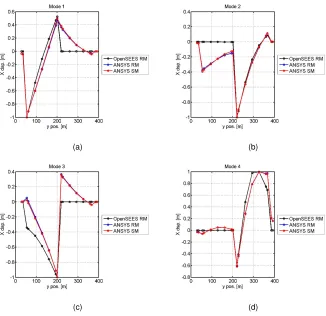
3.24 Eigenmodes of the ANSYS RM of the Rio Torto Bridge in the
non-isolated case:a#1;b#2;c#3; andd#4 . . . 34
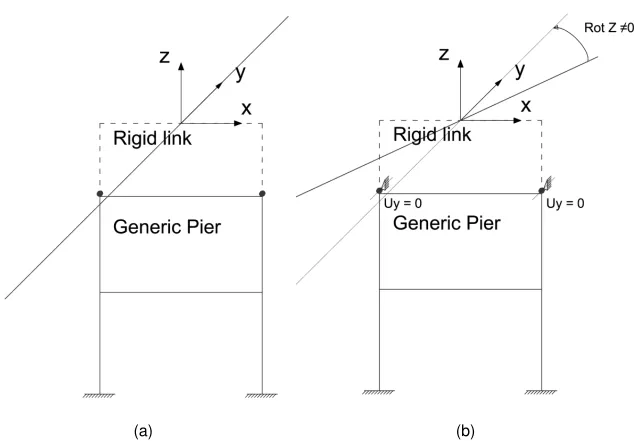
3.25 Deck-pier constraint setting of theaANSYS RM and thebANSYS SM . . . 35
3.26 MAC matrices between a OpenSEES RM and ANSYS RM and b ANSYS RM and ANSYS SM models . . . 36
3.27 To view of deformed shapes of Modesa#1;b#2;c#3; andd#4 . . 37
3.28 Comparison of transversal displacement responses of: a Pier #9; andb Pier #11 measured at cap beam levels. The SLS accelero-gram scaled to 0.05g of PGA was considered as seismic input. . . . 39
3.29 Plan view of the reduced linear ANSYS GM of the Rio Torto Bridge
in the non-isolated case. Reduced S-DoF piers provide transversal
stiffness to the deck. . . 41
3.30 MAC matrices between ANSYS GM and ANSYS SM models . . . . 41
3.32 Displacement response of reduced S-DoF Piers:a#9; andb#11 at
ULS. . . 45
3.33aHysteretic S-DoF oscillator with entailingbbilinear hysteretic loop 45 3.34 Plan view of the reduced nonlinear model of the Rio Torto Viaduct in the non-isolated case . . . 47
3.35 Displacement responses of Piers #9 and #11 at SLS in the non iso-lated case . . . 49
3.36 Displacement responses of Piers #9 and #11 at ULS in the non iso-lated case . . . 50
3.37 Plan view of the reduced nonlinear model of the Rio Torto Viaduct in the isolated case . . . 50
3.38 Displacement responses of Piers #9 and #11 at SLS in the isolated case . . . 52
3.39 Displacement responses of Piers #9 and #11 at ULS in the isolated case . . . 52
3.40 Hysteretic loops of right isolators of Piers #9 and #11 at SLS from OpenSEES RM and reduced model . . . 54
3.41 Hysteretic loops of right isolators of Piers #9 and #11 at ULS from OpenSEES RM and reduced model . . . 54
4.1 Substructuring scheme of the Rio Torto Bridge in the non isolated case . . . 59
4.2 Substructuring scheme of the Rio Torto Bridge in the isolated case . 60 4.3 Mock-up 1:2.5 scale models ofaPier #9 andbPier #11. Dimensions in cm. . . 63
4.4 Transverse element of Pier #11 with reinforcements . . . 64
4.5 Mock-up 1:2.5 scale specimens of Piers #9 and #11 . . . 67
4.6 Scaled FPB device:asection;btop view. Dimension in mm. . . 67
4.7 Experimental set-up conceived for FPB isolation devices of Pier #11 68 4.8 a short actuators for vertical loads; b long actuators for horizontal displacements. . . 68
4.10 Force measurement channels relevant to actuator load cells . . . 71
4.11 Mock-up 1:2.5 scale specimens of Piers #9 and #11 with relevant FPB isolator pairs . . . 73
4.12 Experimental set-up of piers. . . 75
4.13 Sensor set-up of Pier #9. . . 78
4.14 Sensor set-up of Pier #11. . . 79
4.15 Close-up views of: acolumn base LVDT sensor;bLVDT lattice of a transverse beam. . . 80
4.16 Layout of the LVDT lattice installed on transverse beams. . . 80
4.17 a Schematic view of the foreseen arrangement of cameras; b in-stalled acquisition equipment. . . 81
4.18 Acquisition set-up for photogrammetric measurements: atop andb side views. . . 82
4.19 Plan view of the experimental set-up of the FPB device pair . . . 83
4.20 Side view of the experimental set-up of the FPB device pair . . . 83
4.21 Structural scheme of the experimental set-up conceived for each single isolator block . . . 83
4.22 Structural scheme and vertical reactions of the rigid steel frame . . . 85
4.23 Flowchart of the testing procedure applied to the Rio Torto Bridge . 91 4.24 Fiber-based OpenSEES 2D FE model ofaPier #9; andbPier #11 with relevant node numbering. . . 95
4.25 Identified values of maximum compressive strength fpcof OpenSEES concrete01material . . . 96
4.26 Comparison between experimental and numerical hysteretic loops ofaPier #9; andbPier #11 during Test k 09. . . 97
4.27 Hysteretic loops of FPB isolation devices of: aPier #9 during Test d03; andbPier #11 during Test b16. . . 98
4.28 Hysteretic loops of FPB isolation devices of: aPier #9 during Test d02; andbPier #11 during Test b22. . . 99
4.30 Comparison between numerical and experimental responses of: a Pier #9; andbPier #11 during Test k 07, i.e. non-isolated bridge at SLS. . . 109
4.31 Hysteretic loops of top restoring forces ofaPier #9 andbPier #11 during Test k 07, i.e. non-isolated bridge at SLS. . . 110
4.32 Countour plots of axial strain fields at different times of Test k 07, i.e.
non-isolated bridge at SLS. . . 111
4.33a Geometric characteristics of the LVDT lattice; b average shear deformation history of transverse beam of Pier #11 relevant to Test
k 07, i.e. non-isolated bridge at SLS. . . 112
4.34 Close-up views of Pier #11: atransverse beam and bleft column, after Test k 09, i.e. non isolated bridge at ULS. . . 112
4.35 Comparison of hysteretic loops of top restoring forces of:aPier #9; andbPier #11 relevant to Tests k 09 and k 10, i.e. non isolated bridge at ULS and ULS aftershock, respectively. . . 113
4.36 Comparison of displacement responses ofaPier #9 andbPier #11 relevant to Tests k 09 and k 10, i.e. non isolated bridge at ULS and
ULS aftershock, respectively. . . 113
4.37 Comparison of hysteretic loops of top restoring forces ofa Pier #9 andbPier #11 relevant to Tests k 09 and k 12, i.e. non isolated bridge at ULS and ULS 200%, respectively. . . 114
4.38 Comparison displacement responses ofa Pier #9 andb Pier #11 during Tests k 09 and k 12, i.e. non isolated bridge at ULS and ULS
200%, respectively. . . 115
4.39 Close-up views of Pier #11: atransverse beam and b column top after Test k 12, i.e. non isolated bridge at ULS 200%. . . 115
4.40aExpulsion of the concrete cover on transverse beam of Pier #11;b crack pattern of the lower transverse beam of Pier #9 after Test k 12,
i.e. non isolated bridge at ULS 200%. . . 116
4.41 Comparison of hysteretic loops of top restoring forces ofaPier #9b Pier #11 relevant Test l01 and Test k 07, i.e. isolated and non isolated
4.42 Comparison of displacement responses ofaPier #9 andbPier #11 relevant Test l01 and Test k 07, i.e. isolated and non isolated bridge
at SLS, respectively . . . 118
4.43 Comparison of hysteretic loops of top restoring forces ofaPier #9b Pier #11 relevant Test l02 and Test k 09, i.e. isolated and non isolated
bridge at ULS, respectively . . . 118
4.44 Comparison of displacement responses ofaPier #9 andbPier #11 relevant Test l02 and Test k 09, i.e. isolated and non isolated bridge
at ULS, respectively. . . 119
4.45 Comparison of hysteretic loops of top restoring forces of a Pier #9 andbPier #11 relevant Test l01 and Test p01, i.e. SLS with numeri-cal and physinumeri-cal FPB isolators, respectively. . . 120
4.46 Comparison of displacement responses ofaPier #9 andbPier #11 relevant Test l01 and Test p01, i.e. SLS with numerical and physical
FPB isolators, respectively. . . 120
4.47 Hysteretic loops of top restoring forces ofaPier #9 andbPier #11 relevant to Test p02, i.e. ULS 70% with physical FPB isolators. . . . 121
5.1 a3D model of the piping system placed on the support structure;b specifications and dimensions of the piping system after DeGrassi
and Hofmayer (2008). Dimensions are in mm . . . 124
5.2 aSLC reference floor accelerogram;brelevant acceleration response spectrum for 0.5% equivalent viscous damping . . . 126
5.3 Bending moment-rotation relationships of an elbow under bending
loading from ABAQUS FE analyses: ain-plane; andbout-of-plane bending. . . 127
5.4 Experiments on pipe elbows performed by Varelis et al. (2012): a test set-up;bcyclic response . . . 128 5.5 PS, NS and relevant coupling DoFs. . . 129
5.6 Schematic of ANSYS FE models of the piping system showing pipe
sections and significant nodes. . . 131
5.9 Comparison of displacement responses of the RM and M-SEREP
reduced model at coupling DoFsa#1 andb#2. . . 141
5.10 Comparison of displacement responses of reduced models at Cou-pling DoF #1. . . 144
5.11aConstraint Mode #1;bConstraint Mode #2. . . 145
5.12 Fixed Interface Vibrationa Mode #1 at 6.57Hz and b Mode #3 at 12.44Hz of the PS. . . 147
5.13 Comparison of displacement responses of the RM and CB reduced models at Coupling DoFa#1 andb#2. . . 148
5.14 Top view of the experimental set-up of the PS for the purpose of hybrid simulation. . . 149
5.15 Actual experimental set-up for hybrid simulations. . . 149
5.16 LSRT2 algorithm:aspectral radiusρ; andbalgorithmic damping ¯ξ. . 152
5.17aArchitecture of the implementation andbhardware equipment. . . 153
5.18aSchematics of the delay over prediction scheme andb experimen-tal validation of the delay compensation strategy. . . 154
5.19 Acquisition set-up for the dynamic characterization of the PS. . . 155
5.20 Free decay response of the PS subjected to hammer tests. . . 155
5.21 Dynamic characterization of the PS:acluster diagram andb stabi-lization diagram relevant the 32bar water pressure case. . . 157
5.22 Strain history in Elbow #2 at SLCT. . . 157
5.23 Acceleration response of Coupling DoF #2 for PDT at SLC. . . 158
5.24 Displacement response of Coupling DoF #1 for PDT at SLC. . . 158
5.25 Displacement response of Coupling DoF #2 for PDT at SLC. . . 159
5.26 Acceleration response of Coupling DoF #2 for RT. . . 159
5.27 Displacement response of Coupling DoF #1 for RT. . . 160
5.28 Displacement response of Coupling DoF #2 for RT. . . 160
6.1 MG-αmethod: GE. . . 169
6.2 MG-αmethod: spectral radius. . . 169
6.3 MG-αmethod:afrequency error; andbalgorithmic damping. . . 170
6.4 Reference split-mass S-DoF system . . . 171
6.6 GC-MG-α: GE trends withass = 1andbss = 10, i.e. without and with subcycling, respectively. . . 176
6.7 Task sequence of the PM-MG-αmethod. . . 176
6.8 PM-MG-α: GE trends withass = 1andbss = 10, i.e. without and with subcycling, respectively. . . 180
6.9 Task sequence of the GCbis-MG-αmethod . . . 181
6.10 GCbis-MG-α: GE trends witha ss = 1andb ss = 10, i.e. without and with subcycling, respectively. . . 184
6.11 30-DoFs 2D plane structure with PL:a#1;b#2;c#3 and;d#4. . . 185 6.12 Displacement responses at Node #4 in x direction calculated with
theaPM-MG-αand thebGCbis-MG-αmethod . . . 187 6.13 Zoom on displacement responses at Node #4 in x direction
calcu-lated with the:aPM-MG-αand; thebGCbis-MG-αmethod. . . 187 6.14 Benchmark split-mass 3-DoFs stiff system. . . 188
6.15 Displacement responses calculated with the GCbis-MG-α method
with:aρ∞= 1.0; andbρ∞= 0.0. . . 189 6.16 Architecture of experimental implementations of the proposed time
integration algorithms for the purpose of hybrid simulation. . . 190
6.17 Simulink implementation of the GCbis-MG-αalgorithm. . . 191
6.18 Split-mass 4-DoFs chain like system for the experimental validation
of the GCbis-MG-αmethod. . . 191
6.19 Experimental set-up of the PS:aside; andbfront views. . . 192 6.20 SimulatedLink displacement histories of the 4-DoFs chan-like stiff
system at DoFsa#1 andb #4. The GCbis-MG-αmethod was ap-plied with the subcycling setting foreseen for the experimental
vali-dation. . . 193
6.21 Displacement histories of the 4-DoFs chan-like stiff system obtained
with the GCbis-MG-αmethod with:aρ∞= 1.00; andbρ∞= 0.50. . 194 6.22 Displacement history at the Coupling DoF #1 of the piping system
L
IST OFT
ABLES3.1 Heights of piers of the Rio Torto Bridge . . . 17
3.2 Deck cross section properties . . . 18
3.3 Calculation of the linear weight of the deck . . . 19
3.4 Modal characteristics of the ANSYS RM . . . 33
3.5 Comparison of modal frequencies of the models of teh Rio Torto
Bridge . . . 35
3.6 NRMSE between linear responses of piers of OpenSEES RM and
ANSYS models subjected to the SLS accelerogram scaled to 0.05
PGA. . . 38
3.7 Linear parameters of reduced S-DoF piers . . . 40
3.8 Non-linear parameters of S-DoF reduced piers based on modified
Bouc-Wen springs . . . 43
3.9 NRMSEs on displacements, velocities and restoring forces of S-DoF
reduced piers with respect to the OpenSEES RM. . . 44
3.10 External constraints of the reduced model of the Rio Torto Bridge in
the non-isolated case . . . 48
3.11 CEs aimed at implementing Gerber saddles . . . 48
3.12 Reduced model of the Rio Torto Bridge in the non isolated case:
NRMSEs on transversal kinematic histories measured at cap beam
levels of piers based on modified Bouc-Wen springs at SLS and ULS. 49
3.13 CEs aimed at removing Gerber saddles . . . 51
3.14 Reduced model of the Rio Torto Bridge in the isolated case:
NRM-SEs on transversal kinematic histories measured at cap beam levels
3.15 Reduced model of the Rio Torto Bridge in the isolated case:
NRM-SEs on relative displacement and restoring force histories of right
isolators at SLS and ULS. . . 53
4.1 Estimations of shear strengths of full-scale and scaled mid cross
sections of transverse elements . . . 65
4.2 List of actuators, types and purposes. . . 69
4.3 Self weights of set-up elements . . . 76
4.4 Geometric stiffness of piers . . . 76
4.5 Self weights of set-up elements . . . 84
4.6 Characterization tests of FPB isolators of Pier #9. . . 87
4.7 Characterization tests of FPB isolators of Pier #11. . . 87
4.8 Characterization tests of Pier #11. . . 88
4.9 Characterization tests of Pier #9. . . 88
4.10 RETRO tests: hybrid simulations of the Rio Torto Bridge . . . 89
4.11 List of tests followed by characterizations of physical piers, i.e. model
identification of PSs . . . 94
4.12 Friction parameterµof OpenSEESsingle FP bearingelements
iden-tified of physical isolators . . . 98
4.13 Dependencies between nonlinear identification and model updating
sessions. . . 101
4.14 Hybrid simulations of the non isolated bridge: nonlinear parameters
of S-DoF reduced piers. . . 103
4.15 Hybrid simulations of the isolated bridge: nonlinear parameters of
S-DoF reduced piers. . . 105
4.16 Hybrid simulations of the non isolated bridge: NRMSEs on
displace-ment, velocity and acceleration responses of reduced S-DoF piers. . 106
4.17 Hybrid simulations of the isolated bridge: NRMSEs on
displace-ment, velocity and acceleration responses of reduced S-DoF piers. . 108
4.18 NRMSE scores on experimental responses of Piers #9 and #11 with
respect to reduced models of the bridge. . . 108
5.1 PGAs corresponding to Serviceability and Ultimate Limit States of
support structure . . . 125
5.2 Elbow properties considered in the piping system model with straight
elements . . . 129
5.3 First 10 eigenfrequencies and participation masses of the piping
system model . . . 132
5.4 MAC matrix between ANSYS CM and RM models . . . 133
5.5 NRMSE and NEE between RM and CM . . . 134
5.6 Additional nodal masses of the ANSYS MM. . . 135
5.7 Modal frequencies of the ANSYS MM. . . 135
5.8 NEE of reconstructed displacement responses of coupling DoFs
with respect to the RM solution. . . 139
5.9 NRMSE of reconstructed displacement responses of Coupling DoFs
#1 and #2 with respect to the RM solution. . . 139
5.10 M-SEREP method: NEE and NRMSE between RM and Reduced
model . . . 141
5.11 NEE and NRMSE between ANSYS RM and reduced models. . . 144
5.12 CB method: NEEs on coupling DoFs resulting from the sweep
anal-ysis. . . 147
5.13 CB method: NRMSEs on coupling DoFs resulting from the sweep
analysis . . . 147
5.14 Hybrid test program . . . 154
5.15 Dynamic characterization of the PS: frequency and damping values
for both the water pressure values. . . 156
5.16 NEE and NRMSE between experimental and numerical responses
in the PDT case at SLCT . . . 160
5.17 NEEs and NRMSEs between experimental and numerical responses
in the RT case . . . 161
6.1 Modal frequencies of the benchmark plane system. . . 186
6.2 GEs of displacement responses at Node #5 along the x direction
C
HAPTER1
INTRODUCTION
1.1 Hybrid Simulation with dynamic substructuring
Hybrid Simulation with Simulation Substructuring (HSDS) is an experimental
techniques in which the overall dynamic response of a system -structure- is
eval-uated by combining the experimental response of a Physical Substructure (PS),
which is the most critical part, with the numerical response of a Numerical
Sub-structure (NS) (Bursi, 2008). The term hybrid entails an approach that part of
a structural or mechanical system is analytically modeled while the rest is
physi-cally tested. Dynamic substructuring plays a significant role in the field of
struc-tural dynamics and can be seen as a special class of domain decomposition.
Such paradigm originates from the desire to analyze complex problems by
con-sidering separately the problem of its components and the problem of finding the
interface solution (Klerk et al., 2008). It allows for the simulation of a complex
dynamic system by combining its discretised, analytical and experimental parts.
While coupling two or more substructures, two conditions must hold at interface
Degrees-of-Freedom (DoFs): i) compatibility on kinematic quantities and ii) force
balance. Therefore, the so called transfer system, i.e. actuators and relevant
feed-back sensors managed by real-time computers, must reproduce such conditions.
At the same time, a numerical simulation environment solves the NS and the time
integration of coupled equations of motion advances. As a result, dynamics of
both substructures are accurately reproduced, as well as their mutual interactions.
HSDS does integrate cutting-edge research obtained from the fields of numerical
system modeling. When the PS shows a rate independent behavior, HSDS can be
conducted at extended time scales, typically 50−200times slower than the actual
earthquake time. This is the case of Pseudo-Dynamic Testing (PDT). Accordingly,
inertial and damping components of restoring forces are numerically simulated.
Conversely, when rate dependent effects are significant, a Real-time Testing (RT)
strategy must be selected to obtain reliable simulations. Since experimental
set-ups are restricted to PSs, HSDS facilitates the simulation of full-scale structural
systems. As a result, costs and efforts required to conduct a shake table test on
the entire system are significantly reduced.
1.2 Original scientific contributions of the thesis
HSDS is a powerful and costs saving tool for testing complex and large
dy-namic systems. Within its the scope, the performed research activity focused on
three main objectives: i) the modeling of tunable nonlinear NSs for the purpose of
the hybrid simulation of the Rio Torto Bridge, where a consistent degradation all
piers, i.e. physical and numerical, was needed; ii) the implementation of hybrid
simulations of an industrial piping system characterized by a twisted and branched
PSs with a reduced number of actuators; iii) the development of hybrid compatible
partitioned time integration algorithms tailored to first order systems and prone to
parallel implementations. Different branches of numerical analysis were involved;
in particular, model updating, model reduction and time integration. Experimental
case studies corroborated all numerical advances. Major scientific contributions
are summarized herein for all the aforementioned topics.
The need for assessing the seismic performance of an old reinforced concrete
bridge characterized by nonlinear hysteretic piers and isolators motivated the
de-velopment of reduced nonlinear NSs for the purpose of hybrid simulation.
Charac-terized by a total span of 400m and plain steel bar reinforcements, the Rio Torto
Bridge was underdesigned with respect to seismic requirements dictated by both
Italian and European codes. The installation of a pair -one per column- of Friction
Pendulum Bearing (FPB) isolation devices interposed between the deck and the
cap beam of each pier portal frame was proposed as seismic retrofitting. In order
to simulate the dynamic response of one of the two independent roadways, a
non isolated cases. Since preliminary numerical simulations highlighted the
hys-teretic response of piers already at serviceability limit state (Paolacci and Giannini,
2012), nonlinear NSs were deemed necessary to conduct realistic hybrid
simula-tions. Entailing parameters were tuned according to the fiber-based OpenSEES
FE Reference Model (RM) of the bridge. As a result, hybrid simulations of the
Rio Torto Bridge were successfully implemented at the ELSA Laboratory of the
Joint Research Centre of Ispra (VA), Italy. The PM method (Pegon and Magonette,
2002), which embeds subcycling capabilities, allowed for the implementation of the
continuous PDT method. In order to simulate a consisted degradation of physical
and numerical piers, a novel testing procedure was developed. It was based on
recursive model identification of PSs and updating of NSs.
In the case of simple structural topologies, i.e., shear type frames, inverted
pendulum systems, chain like systems, etc., few actuators handling the totality of
physical DoFs can efficiently reproduce the response path of tested specimens;
and the system of equations of motion can be solved through suitable time
integra-tors. Nonetheless, this approach is not suitable for dealing with complex Physical
Substructures (PSs) subjected to distributed inertia forces, where a plenty of
phys-ical DoFs come on stage; and this is the case of typphys-ical piping networks subjected
to seismic loading. The need for assessing dynamic responses of typical industrial
piping systems motivated the application of model reduction techniques to
exper-imental dynamic substructuring. Therefore, RTs and PDTs of the piping system
were successfully implemented. In particular, the LSRT2 time integration
algo-rithm (Bursi, 2011) was applied in both the two cases. The delay compensation
strategy proposed by Wu (2013) and based on the over prediction of the actuator
command was selected to conduct RTs.
Todays state of the art servo-hydraulic control systems run at sampling times
∆t of the order of 1msec and below. With regard to the continuous PDT method, this means that new displacement values are required at very short and
determin-istic time intervals for the signal generation of actuator commands. On the other
hand, the numerical integration of the equation of motion can be very time
con-suming in the case of complex NSs. Hence, both the computational driver and the
greater computational efficiency, one must be able to solve numerical and
physi-cal subdomains separately with different time steps and then couple their solutions
together. Therefore, parallel partitioned time integration algorithms, which allow
for the concurrent solution of involved subdomains, represent a suitable approach.
Since numerical models of both NSs and PSs can be profitably used for dynamic
identification, model-based control and model order reduction, a unique
represen-tation of the system is preferable. As a result, the most flexible state space form is a
reasonable choice. From this perspective three partitioned hybrid compatible time
integration algorithms were developed for first order systems. They inherited the
favorable user controlled algorithmic damping feature of the Generalized-αmethod
after Jansen et al. (2000).
1.3 Structure of the thesis
This thesis summarizes research activities performed by the author.
Develop-ments of novel methodological approaches and algorithms are presented and the
validated throughout realistic case studies. The remainder of the thesis is divided
in six chapters:
• Chapter 2: The reference literature involved in the present research activ-ity was summarized. In detail, open challenges in HSDS were emphasized
through a review of more recent developments and case studies.
• Chapter 3: First, the Rio Torto Case Study was introduced and both the as-built and the retrofitted configurations were discussed. Then, the OpenSEES
RM was presented to support the implementation of hybrid simulations.
Re-sults of time history analyses of the OpenSEES RM justified the selected
substructuring scheme. In greater detail, the Guyan method (Guyan, 1965)
was applied to each pier portal frame to obtain reduced linear stiffness and
mass. Resulting S-DoF reduced models were extended to the nonlinear
range by means of nonlinear springs capable of reproducing displacement
responses of OpenSEES piers. With regard to FPB isolation devices,
suit-able S-DoF reduced models were tailored according to the state space
bi-linear model of Mostaghel (1999). Validations of reduced models of the Rio
conclu-sions were drawn.
• Chapter 4: First, substructuring schemes and entailing experimental set-ups tailored to the Rio Torto Case Study were discussed. Then, the scaling of
specimens was described. A novel testing procedure aimed at simulating a
consistent degradation among physical and numerical piers, i.e. PSs and
NSs, was presented and applied to the Rio Torto Bridge. It was based on
off-line sessions of model identification of PSs and updating of NSs.
Ac-cordingly, a tool for the identification of parameters of OpenSEES FE models
was implemented in the Matlab environment. As a result, physical piers were
characterized after each test where damage was observed. The OpenSEES
RM model of the Rio Torto Bridge was updated accordingly and took as
ref-erence for the updating of reduced S-DoF piers, i.e. NSs. As a result, a
consistent degradation of physical and numerical piers was simulated in both
non isolated and isolated conditions. Finally, results of hybrid simulations
were discussed.
• Chapter 5: Before introducing any reduction strategy, a clear insight into the dynamic response of the industrial piping system was provided from
a PS perspective. In detail, the Principal Component Analysis (PCA) was
exploited. Accordingly and complying with experimental limitations of each
testing strategy, consistent reduction bases were defined for both PDT and
RT techniques in the case of an elastic response of the PS. Successively,
a Modified version of the System Equivalent Reduction-Expansion Process
(M-SEREP) (OCallahan and Riemer, 1989) and Craig-Bampton reduction
methods (Bampton, 1968) were employed for the reduction of both the PS
and distributed earthquake forces. This allowed for an effective experimental
testing of the actual system. Two further reduction bases were investigated
from a numerical perspective only. Finally and in view of validation, relevant
implementations and experimental results were shown.
• Chapter 6: First, the monolithic MG-αalgorithm was introduced for the un-coupled case. Its stability, accuracy and spectral properties were investigated
the GC-MG-αand the PM-MG-αpartitioned time integration procedures
fol-lowed. The former, which consists of a staggered scheme, was proposed
as starting procedure of the latter, which is a parallel scheme not self
start-ing, within the same implementation. Then, the parallel partitioned
GCbis-MG-αmethod was introduced as an alternative approach. Features of both
strategies were analyzed on numerical case studies. Finally, experimental
validations were discussed.
C
HAPTER2
HYBRID SIMULATION WITH DYNAMIC SUBSTRUCTURING:
STATE-OF-ART OPEN CHALLENGES
Hybrid Simulation (HS) with Dynamic Substructuring (DS) is an experimental
tech-nique that combines the experimental response of a Physical Substructure (PS),
which is the most critical part of the emulated system, with the numerical response
of a Numerical Substructure (NS). A standard computer solves the equation of
motion of the hybrid system by means of a compatible time integrator and the
interaction between NS and PS can be simulated. In detail, at each time step,
ac-tuators impose calculated displacements to specimens through a set of interface
Degrees-of-Freedom (DoFs). Then, measured feedback forces enter the dynamic
balance equation of the entire emulated system and the integration loop advances
(Bursi, 2008).
2.1 Model updating in HSDS
Since the PS gathers components lacking of predictive numerical models, the
application of hybrid simulation is not ideal for structures characterized by complex
nonlinearities distributed to the overall emulated system. As a matter of example,
this is the case of multi-pier bridges. In fact, due to the high cost for providing
an experimental testing environment for a single specimen, hybrid simulation of
such systems normally involve at most one or a few experimental piers. The
re-mainder are reasonably replaced by their numerical counterparts. As a result, it
is very likely that combined PSs and NSs show incompatible structural responses,
despite their similar prototypes. As far as the demand for more and more realistic
becomes the imperative. From this perspective, the measured response of the
experimental specimen could supply information to calibrate numerical parts and
the accuracy of hybrid simulation would benefit from improved models. By reducing
the discrepancies between the response of the mathematical model and that of the
actual system, model updating represents a suitable approach aimed at identifying
system parameters. Over the last two decades, model updating and system
identi-fication techniques were extensively applied to improve the prediction of numerical
models by identifying related parameters on the actual structural response.
Finite element (FE) model updating has been around for more than two decades.
Most of the established FE model updating techniques exploits linear models
(Mot-tershead and Friswell, 1993; Mot(Mot-tershead et al., 2011). However, since the
simu-lation of complex structural systems characterized by critical subparts represents
the strong point of hybrid simulation, typically, responses experienced by tested
specimens span the nonlinear range. Therefore, nonlinear models are amenable
to hybrid applications where a damage process involving hysteresis is often
inves-tigated (Bursi, 2012). Modeling and identification of nonlinear systems of structural
elements in extreme loading conditions is challenging, and particular care must be
devoted to check the well-posedness and the well-conditioning of the associated
optimization problem. Moreover, one is forced to admit that there is no general
analysis method that can be applied to all systems in all instances. The reason is
that the functional, which maps the input to the output, is not known beforehand
(Kerschen et al., 2006). Since in post-experiment parameter identification there
are usually no constraints on computational and data processing times, model
updating is typically performed offline. With recent significant advances in
em-bedded systems and their real-time computing capabilities, online updating can
be performed. In this particular case, algorithms must converge smoothly and
rapidly to proper parameter values in order to capture parameter changes as time
progresses. In recent years, many techniques were developed for this purpose,
including least squares estimation (Smyth et al., 1999), the Extended Kalman
Fil-ter (EKF), the Unscented Kalman filFil-ter (UKF) and the Particle FilFil-ter (PF) (Chatzi
and Smyth, 2009). Time-frequency domain approaches relying on the Short Time
et al., 2013). With reference to the hybrid simulation framework, Kwon and
Kam-mula (2013) developed an online model updating scheme based on several
alter-native numerical models, formulated encompassing the possible variation in the
hysteretic behavior of the tested specimen. In detail, an online optimization
pro-cedure provided instantaneous estimations of a set of weighting factors, which
allowed for reproducing the measured response as a weighted combination of the
responses of a bunch of models. Therefore, if one of the implemented models
ex-actly matches the specimen, the weighting factor for that model tends to one, whilst
the remainder goes to zero. Song and Dyke (2013) developed a cyber-physical
ex-perimental platform based on the UKF to conduct real-time model updating of
non-linear dynamic systems. The objective was to perform the updating computation in
hard real-time, so that an updated model evolves during and is available
immedi-ately after the dynamic input ends. Yang (2012) proposes an online procedure for
the purpose of hybrid simulation of a bridge with multiple identical piers. During a
hybrid simulation, the set of identified parameters that matches the experimental
data measured from the physical specimen was identified and identical NSs were
contemporary updated. Two variant were presented, and they were based on the
Nelder-Mead Simplex method and the UKF, respectively.
According to the need for being updated during the experimental simulation,
Hashemi et al. (2014) proposed a straightforward classification of NSs: i) NSs with
properties similar to tested PSs and experiencing very similar loading histories; ii)
NSs with properties similar to tested PSs and experiencing different loading
histo-ries; and iii) remainder NSs that are no similar to tested PSs. For the first category
of NSs, the experimental response could be used directly to update NSs
param-eters. With regard to the second category of NSs, numerical parameters can be
updated with some conversion or modification. Discussed state-of-art case studies
fall within first two categories and exploit online implementations. In the author’s
knowledge, there is a lack of publications concerning the third, and most
challeng-ing, category where completely different NSs and PSs are of concern. Moreover,
so far, nobody investigated the interaction between estimator and emulated system
2.2 HSDS of PSs characterized by a complex geometry
Since the introduction of the HSDS technique to evaluate seismic performance
of structures, simple structural schemes of PSs and NSs confined its
applicabil-ity range. In fact, shear type frames, inverted pendulum and chain-like systems
were traditionally tested as PSs. Nevertheless, such approach fails in the case of
complex specimens characterized by a number of DoFs greater than the actuator
provision. In the author’s knowledge, very few attempts were done to overcome
this limitation. Hashemi and Mosqueda (2014) developed an innovative HSDS
technique for multistory building and based on subdomain overlapping. Additional
sensing of internal member forces in experimental columns were used within the
feedback loop for the HSDS. One assumption used in the past was a pin at the
likely inflection point of beams and columns. The pin simplifies the interface
be-tween numerical and experimental substructures and conveniently does not
re-quire control of rotations and moments at the boundaries. However, except first
story columns, the remainder usually displays a random distribution of its position.
Since typical industrial plants are characterize by complex geometries, they are
not prone to classic HSDS implementations, where PS matrices are condensed at
few interface DoFs. Nonetheless, piping systems play a highly important role in
many industries, such as petrochemical, oil and gas and nuclear plants, and a
sin-gle failure can trigger serious accidental chains. Therefore, a special attention to
evaluate their safety represents an imperative requirement. In fact, such systems,
elbows, Tee joints and flange joints as well as support structures suffered
signif-icant damages during recent earthquakes causing severe losses both to human
lives and to environment (Krausmann et al., 2010; Paolacci et al., 2013). This led
researchers to carry out considerable studies on the seismic safety assessment of
piping systems and their components (Touboul, 2006; Reza, 2013). However, so
far only few experimental investigations -mainly through shaking table tests- have
been performed on such structures at full-scale under realistic seismic loading
(De-Grassi and Hofmayer, 2008; Otani and Shiratori, 2011). The need for applying the
hybrid simulation technique to typical industrial plant components in a realistic
represents an impelling need.
A lot of effort was devoted to couple numerical and physical substructures in
the context of linear system theory (Rixen and van der Valk, 2013; Voormeeren
and Rixen, 2012), where frequency- and impulse-response-based approaches are
allowed. Although HSDS offers a powerful framework for combining physical and
numerical subsystems, there is still a lack of effective and flexible methods that
enable the implementation of geometrically complex PSs.
2.3 Partitioned time integrators for continuous testing
While coupling two or more substructures, two conditions must hold at interface
DoFs: i) compatibility on kinematic quantities and ii) force balance. Therefore, the
so called transfer system, i.e. actuators and relevant feedback sensors managed
by real-time operating systems, must reproduce such conditions. Concurrently, the
computational driver provided with the numerical simulation environment solves the
NS and integrates the coupled equations of motion. When PSs show a rate
inde-pendent behaviour, extended experimental time scales can relax testing limitations
owing to control accuracy and actuator capacity. Typical time scales λrange
be-tween 50 and 200, and this is the case of Pseudo-Dynamic Testing (PDT), where
inertial and damping components of physical restoring forces are numerically
sim-ulated. Conversely, when rate dependent effects are significant, no extended time
scales can be exploited and Real-time Testing (RT) strategy must be selected, i.e.
λ= 1. For the sake of simplicity, HSDS refers to the PDT case in the present
pa-per. As far as complexity of emulated structural systems increases, the role of time
integration becomes more and more crucial. In fact, todays state-of-the-art
servo-hydraulic control systems run at sampling times∆tof the order of 1 ms and below.
This means that new displacement values are required at very short and
determin-istic time intervals for the signal generation of smooth actuator commands, which
preserve the optimum signal/noise ratio of the continuous testing method. On the
other hand, the computational driver can take much more time to solve complex
NSs and to integrate the equation of motion. Necessarily, numerical and
physi-cal sides run at different rates and the need for a synchronization of the two time
integration processes arises.
al-low for the concurrent solution of involved subdomains with different time steps,
represent a very attractive approach. In fact, they maintains the smoothness of
the displacement trajectory avoiding any extrapolation/interpolation assumption. In
particular, the Finite Element Tearing and Interconnecting (FETI) method emerged
as one of the most powerful domain decomposition method for quasi-static
me-chanical problems (Farhat and Roux, 1991); later, the FETI was extended to
tran-sient problems (Farhat et al., 1995). In order to couple involved subdomains,
Lagrange multipliers impose continuity conditions at the shared interface nodes.
Gravouil (2001) proved that velocity continuity at the interface leads to a stable
al-gorithm. In particular, they conceived a multi-time-step coupling method, labelled
as the GC method, able to couple arbitrary Newmark schemes with different time
steps in different subdomains. In this context, they proved that the GC method is
unconditionally stable as long as all individual subdomains satisfy their own stability
requirements. Unfortunately, the GC is a sequential staggered algorithm where the
tasks in different subdomains are not concurrent. In order to solve this problem,
Pe-gon and MaPe-gonette (2002) developed and implemented an enhanced parallel
par-titioned algorithm, the PM method; it was based on the GC method, but the NS and
the PS states advance simultaneously and continuously, as proved in the
labora-tory on several structural hybrid systems. The PM method was deeply investigated
by Bonelli et al. (2008), who proved its convergence and stability characteristics.
Energy dissipation at the interface and the loose of one order of accuracy in the
case with subcycling were pointed out as major drawbacks. Bursi (2010) proposed
an extension of the PM method that enables arbitrary Generalized-αschemes to
be coupled with different time steps in each subdomain, i.e. the PM method. The
Generalized-α method is well known for its favorable user controlled algorithmic
damping feature that allows for filtering out spurious high-frequency components
but preserving low-frequency components. Prakash and Hjelmstad (2004)
devel-oped a variant of the GC method, the so-called PH method, achieving energy
preservation by eliminating the calculation of interface reactions at the fine time
step. Nonetheless, the PH method remains a staggered procedure. In fact,
resid-uals of the interpolated balance equation of the free problem related to the coarse
the free problem related to the fine grid subdomain. As a result, the PH method
preserves second order accuracy in the case with subcycling but negates for the
implementation of continuous HSDS. The GCbis method developed by Mahjoubi
(2010) overcame such strict limitation. In particular, the same interpolation
set-ting of the GC method was applied to free kinematic quantities, whilst interface
reactions were calculated at coarse time steps as for the PH method. Hence,
in-terpolated Lagrange multipliers entered the balance equation of the subdomain
characterized by the finer time step in place of aforementioned residual interface
forces. As a result, no information exchange between subdomains was required
and parallel implementations were enabled. Moreover, the self-starting capability
of the GCbis method, which paves the way for simpler implementations, makes it
very attractive for the purpose of HSDS despite it is not yet considered.
All partitioned time integration algorithms described so far apply to the
Euler-Lagrange form of the equation of motion. Within the framework of partitioned time
integrators applied to the Hamilton form of equations of motion, Nakshatrala et al.
(2008) proposed a FETI-based staggered method capable of accommodating
dif-ferent time integrators and time steps in diverse subdomains. This was made
pos-sible by using a differentiated kinematic constraint and by rendering explicit the
cal-culation of interface Lagrange multipliers. The proposed method was non A-stable
and stabilization techniques depending on arbitrary constants where required to
reduced drift-off effects on interface quantities. Along the same line, Bursi et al.
(2012) developed two partitioned schemes with subcycling capabilities but prone
to parallel implementations. Both coupling schemes were conceived to combine a
pair of Linearly Stable Real-Time (LSRT-2) compatible monolithic time integrators
of the Rosenbrock type (Bursi et al., 2008). Both the primal, labelled as Parallel
LSRT-2 (PLSRT-2), and its improved version, denoted as IPLSRT-2, operate with
differentiated kinematic constraints applied to interface accelerations; therefore,
first they explicitly solve the interface problem by means of Lagrange multipliers
and then, they advance the solution in all the subdomains. Since both the PLSRT-2
and the IPLSRT-2 were not endowed with self-starting capabilities, modified
stag-gered implementations were implemented as initialization procedures. Therefore,
C
HAPTER3
DYNAMIC SUBSTRUCTURING OF THE FIBER-BASED
FINITE ELEMENT MODEL OF THE RIO TORTO BRIDGE
FOR HYBRID SIMULATION PURPOSES
3.1 Introduction
The assessment of seismic performances of an old concrete bridge was
con-ceived within the RETRO transnational activity funded by the SERIES European
project (Fardis, 2009). The aim of the research study was twofold: i) to investigate
the nonlinear response of reinforced concrete pier portal frames provided with plain
steel reinforcement bars; ii) to estimate the effectiveness of seismic isolation
sys-tems applied to this class of structures. In particular, the Rio Torto Bridge was
se-lected as case study. Characterized by 400m of total span and plain steel bar
rein-forcements, it was underdesigned with respect to seismic requirements dictated by
both Italian and European actual codes (NTC-2008, 2008; EUROCODE-8, 2004).
The installation of a pair -one per column- of Friction Pendulum Bearing (FPB)
iso-lation devices interposed between the deck and the cap beam of each pier portal
frame was proposed as seismic retrofitting. In order to simulate the dynamic
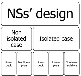
re-sponse of one of the two independent roadways, a comprehensive set of hybrid
simulations was conceived for both the isolated and the non isolated cases. Since
piers exhibited hysteretic responses already at serviceability limit state, nonlinear
NSs were deemed necessary to conduct realistic simulations. Entailing
param-eters were tuned according to the fiber-based OpenSEES FE Reference Model
(RM) of the bridge. First, the Rio Torto case study is introduced and both the
(a)
(b) (c)
Figure 3.1: aView of the Rio Torto viaduct,bDetail of portal piers,cDetail of the deck
is presented to support the implementation of all NSs. Results of time history
analyses of the OpenSEES RM justified the selected substructuring scheme. In
greater detail, the Guyan method (Guyan, 1965) was applied to each pier portal
frame to obtain reduced linear stiffness and mass. Resulting S-DoF reduced
mod-els were extended to the nonlinear range by means of nonlinear springs capable of
reproducing the displacement responses of OpenSEES piers. With regard to FPB
isolation devices, suitable S-DoF reduced models were based on a bilinear state
space model (Mostaghel, 1999). Validations of reduced models of the Rio Torto
Bridge based on substructured components follow. Finally, conclusions are drawn.
3.2 Description of the case study
The Rio Torto Bridge is characterized by two independent roadways. Twelve
portal piers support each thirteen-span deck. Extreme spans measure 29m, whilst
internal span 33m. Figure 3.1 collects views of viaduct portal piers and concrete
Figure 3.2: Structural scheme of the Rio Torto Bridge
Pier Height [m] Pier Height [m] Pier Height [m]
1 17.35 5 27.86 9 25.74
2 30.61 6 39.41 10 17.19
3 30.49 7 41.34 11 14.37
4 26.75 8 36.49 12 13.80
Table 3.1: Heights of piers of the Rio Torto Bridge
portal frame is composed by two solid or hollow circular columns of variable
di-ameter, 1200mm and 1600mm, respectively. They are connected by a cap-beam
at the top and by one or more transverse beams of rectangular section at
inter-mediate levels. Table 3.1 summarizes heights of piers. As can be appreciated in
Figure 3.2, six Gerber saddles are placed in the middle of the bridge and close
to both abutments. Figure 3.3 reports a close-up view of one of the Gerber
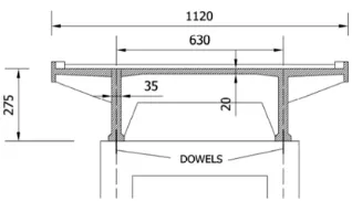
sad-dles. As highlighted by Figure 3.4, which depicts the cross section of the deck,
two vertical dowels constraint the deck to each pier. Conversely, abutment
bear-ings are realized with fixed devices. Geometrical properties of the cross section
of the deck are reported in Table 3.2. The calculation of the linear weight of the
deck is summarized in Table 3.3. In order to achieve seismic performance
re-quirements of EUROCODE-8 (2004), the removal of Gerber saddles and the
in-stallation of a pair of FPB isolators -one per column of each pier- were proposed
di-Figure 3.3: Detail of one Gerber saddle
Figure 3.4: Cross section of the deck
Area [m2] Ix [m4] Iz [m4] J[m4]
4.63 3.45 51.90 0.1027
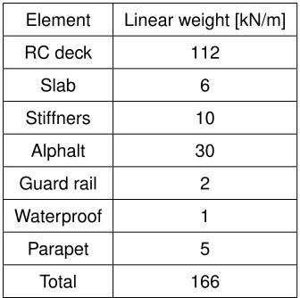
Element Linear weight [kN/m]
RC deck 112
Slab 6
Stiffners 10
Alphalt 30
Guard rail 2
Waterproof 1
Parapet 5
Total 166
Table 3.3: Calculation of the linear weight of the deck
Figure 3.5: Layout of isolation devices on a generic piers
rect displacement-based procedure proposed by Priestley (2007). It focused on
two objectives: i) to keep pier responses in the elastic range; ii) to minimize the
displacement demand at abutment expansion joints. The design of the isolation
system for the Rio Torto viaduct can be found in De Risi and Taucer (2011).
Ac-cording to Figure 3.5, each pair of FPB devices were interposed between the cap
beam of the relevant pier portal frame and the deck. In greater detail, isolators
with one spherical sliding surface with an height of articulated slider of 90mm were
considered to seismically isolate the Rio Torto bridge. As shown in Figure 3.6, the
basic elements of the single-surface FPB device are: the upper anchor plate (1),
the sliding surface (2), the sliding material interface (3), the rotation element (4),
the rotation sliding surface (5) and the lower anchor plate (6). As can be
(a) (b)
Figure 3.6:ascheme of a single-surface FPB device and itsbtypical shear hysteretic loop
greater detail their beahviour can be expressed by the bilinear force displacement
relationship of Eq. 3.1.
VFPB =µfN + N
R∆iso (3.1)
where: VFPB is the shear restoring force, µf is the friction coefficient, N is the vertical load, R is the curvature radius of the device and ∆iso is the sliding
dis-placement in the isolator. With reference to full-scale dimensions, the radius R of
the FPB used for the seismic retrofitting of the Rio Torto was 3.00m and a 4.00%
friction coefficientµf was assumed. The initial yield displacement of devices was 0.5mm. Since each pier portal frame bears a vertical load varying between 5600kN
and 5300kN, the vertical load N acting of the single device varies between 2800kN
and 2650kN. The threshold shear force was 7500kN. The E-W and the N-S
com-ponents of the Emilia earthquake of 2012 were considered as Serviceability Limit
State (SLS) and Ultimate Limit State (ULS) seismic actions, respectively. Figure
3.7 depicts both accelerograms. The SLS accelerogram was characterized by
2.56m/s2PGA, whilst the ULS accelerogram by 2.67m/s2PGA. Relevant acceler-ation and displacement response spectra are compared in Figure 3.8. With regard
to Figure 3.8, dash lines correspond to first four fundamental periods of the bridge
obtained from the modal analysis of the OpenSEES RM presented in the next
sec-tion. Though PGAs are very close, corresponding displacement and acceleration
(a) (b)
Figure 3.7: aSLS andbULS accelerograms
(a) (b)
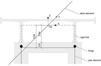
Figure 3.9: Details of the FE model of the pier-deck connection (dimensions in m)
3.3 The OpenSEES FE Reference Model
In order to support the design of hybrid simulations, a refined OpenSEES
fiber-based FE RM able to simulate the hysteretic behavior of piers was set (Paolacci
and Giannini, 2012). Piers were considered clamped at the base; translational
DoFs of both abutments were fixed whilst rotations released. To take into account
the offset distance between the center of gravity of the deck cross section and the
cap beam axis, each pier was connected to the deck through a rigid link. In detail,
each rigid link was considered fixed to the deck and hinged to the relevant pier, as
shown in Figure 3.9. Gerber saddles were modeled as hinges allowing for
longitu-dinal and transversal shear transfer. Linear beam elements were adopted to model
the deck. Piers were discretized with nonlinear beam elements. In greater detail,
fibers elements were considered. They allowed for an accurate discretisation of
cross sections, reproducing the exact position and dimension of reinforcing bars
and concrete with relevant constitutive laws. Figure 3.10 depicts the OpenSEES
fiber based FE model of Pier #12 characterized by solid cross section columns.
According to previous experimental tests, the contribution of the concrete tensile
strength may be neglected in the case of plain steel bars and poor seismic details
(Alessandri, 2013). As a consequence, the Kent-Scott-Park model was employed
to simulate the concrete behavior (Kent and Park, 1971) that is implemented in
theConcrete01OpenSEES material. According to Figure 3.11, which depicts the
constitutive law of the Concrete01 material, a first parabolic branch reaches the
maximum compressive strength $fpc, which was assumed equal to 26MPa; the
Figure 3.10: Scheme of the OpenSEES fiber-based FE model of Pier #12
Then a decreasing linear branch connects the maximum compressive strength $fpc
and the ultimate compressive strength $fpcu, which was assumed equal to 22MPa
with a corresponding ultimate strain $epsU of 0.6%. Reinforcing steel bars were
modeled according to the Menegotto-Pinto constitutive law (Menegotto M., 1973),
which is implemented in theSteel02OpenSEES material. Figure 3.12 depicts the
relevant constitutive law. The yielding stress fy was assumed equal to 360MPa,
along with a Young modulus of 205000MPa; the hardening parameter was set
equal to 0.025. A phenomenological shear-strain hysteretic relationship was
as-sumed for the shear nonlinear behavior of the transverse beam in the presence of
plain longitudinal bars. It consisted of a trilinear envelope curve. The influence of
axial forces was neglected. It was implemented by means of the OpenSEES
hys-tereticmaterial whose force-deformation relationship is depicted in Figure 3.13. In
particular, forces were obtained according to the formulation proposed by Priestley
et al. (1994), based on the Modified Compression Field theory (Vecchio, 1988).
The total shear strength Vt is the sum of concrete and reinforcement contributions, i.e.
(a)
Figure 3.11: Constitutive laws ofconcrete01OpenSEES materials
(a)
Figure 3.12: Constitutive laws ofsteel02OpenSEES materials
(a)