INTRODUCTION
The criterion for having a homogenous tem-perature profile in a rapid compression machine (RCM) is creating a crevice volume on the periph -eral surface of the piston head. The essence of this volume is to curtain the vortex deposited in front of the piston face at the end of the stroke. This vor -tex emerges as a result of the piston scrapping the cool boundary layers from the walls of the cham -ber and depositing it in front of the reactor piston. The design of a piston head configuration plays a significant role in maintaining a homogeneous temperature field. It helps minimise the non-ideal influences as a result of piston movement which induced roll-up vortex and non-uniform heat re -lease in RCM. Creviced pistons are designed with a machine tapered gap and opened volume around the circumference of the piston. The ta -pered gap swallows the boundary layer gasses
near the chamber walls and prevents them from emerging onto the surface of the piston face. The geometrical shape of the piston crevice design is important, as it could prevent the gas flow back into the reactor chamber. Mittal and Gupta [1] carried out a study on the impact of crevice con -tainment where they designed a stepped combus -tion chamber and used a seal between the crevice and the stepped chamber; their result showed that the roll-up vortex was suppressed and no negative influence of the fluid flow was observed [1]. The mass flow of gases from the reaction chamber, through the tapered gap to the crevice, is driven by a pressure differential that exists between the reactor chamber and crevice as proofed by CFD modelling [2].
The experimental data obtained from RCM could be influenced negatively if the scrapped cold gases from the chamber walls mix in the core region of the chamber. This mixing creates ther -Volume 13, Issue 1, March 2019, pages 46–51
https://doi.org/10.12913/22998624/103380
CFD study of the Effect of Piston Crevice Volume on the
Temperature Distribution in a Rapid Compression Machine
Oku E. Nyong
1*, Celestine Ebieto
2, Ene Ekpo Bassey
1, Ikem Azorshubel Ikem
11 Energy and Fluid Science Engineering Group, Department of Mechanical Engineering, Cross River University
of Technology, Calabar, Nigeria
2 Department of Mechanical Engineering, University of Port Harcourt, Rivers State, Nigeria
* Corresponding author’s e-mail: [email protected]
ABSTRACT
One of the conditions for controlling the aerodynamics in the reaction chamber is designing a crevice volume on the surface of the piston head. The importance of the crevice volume is to contain the cool boundary layers gener
-ated as a resulting of the moving reactor piston. However, this crevice volume consequently drops the end gas pressure and temperature at the end of the stroke. The CFD study of the aerodynamic effect of a piston movement in a reaction chamber was modelled using the commercial code of Ansys Fluent and assuming a 2-Dimensional computational moving mesh. A starting optimal crevice volume of 282 mm3 was used for further optimisation. This resulted in five crevice lengths of 3 mm, 5 mm, 7 mm, 9 mm and 12 mm, respectively. The crevice height of 5 mm was found to improve the compressed gas pressure at the end of the stroke to about 2 bar and temperature about 17.7 K and also maintained a uniform temperature field, while that of 12 mm had the least peak compressed gas pressure. This study investigated the possible means of improving the peak pressure and temperature drop in a rapid compression machine by further optimisation of the crevice volume.
Keywords: Rapid compression machine; CFD; Crevice piston; Piston stroke; Optimisation.
Research Journal
Accepted: 2019.02.12mal stratification contained by the charge making it problematic to deduce data, therefore giving confusing results [3÷7]. This hinders the unifor -mity of the core region where kinetics of combus -tion is predominantly present. Igni-tion delay is one of the measurable parameters in RCM exper -iment, understanding the combustion chemistry is relevant and as such, it should be designed to reduce the fluid motion effect, which may result in the inconsistency of data. The heat loss effect should also be taken into consideration to define the reaction temperature through a simple mod -el that could adequat-ely mod-el the system. This is attained with the use of the zero-dimensional approach which characterises the nature of the RCM and viability of the recommended approach can only be valid if the RCM has a homogenous core region which is established by using a prop -erly designed piston head crevice. Optimisation of crevice geometries was undertaken for various RCM’s machines resulting in the use of different crevice shape and volume [8÷11]. A crevice vol -ume was employed on the surface of the piston head; a few may utilise a long and narrow crevice volume [12]. This idea was initiated by Park [13] and further developed by Lee and Hochgreb [14]. Further progress was made on Park’s design by changing the overall geometry of the crevice as well as increasing the original cross-sectional vol -ume of the crevice [12]. The work by Desgroux et al. demonstrated that their piston head crevice was capable of controlling the roll-up vortex pro -duced in their RCM design [4]. Further computa -tional fluid dynamics study on the physics of the temperature homogeneity, roll-up vortex structure and formation in the combustion chamber were discussed by the previous author both numeri -cally [8, 9, 11, 15, 16] and experimentally [17]. The kinetics modelling was also reported; certain assumption of heat released through the combus -tion chamber was examined and then compared the zero-dimensional code with the CFD codes [18÷20]. The uniformity of temperature profile in the chamber is influenced by the physical prop -erties of the compressed mixture. This impact was studied by Wurmel et al. [19] where certain inert gases could increase or decrease the peak pressure and temperature because of the differ -ences in their specific heat values. Other ways by which the end gas temperature and pressure are improved could involve increasing the initial pressure of the chamber, the temperature and in -creasing the stroke length, which improves the
compression ratio of the end gas pressure. This study investigated designing a suitable piston crevice volume that is capable of suppressing the multidimensional effect such as roll-up vortex, thus maintaining homogeneity of the core region of the chamber and equally improving the end gas pressure as well as temperature drop through op -timisation of the crevice volume.
COMPUTATIONAL METHOD
conver-gence problems as well as limiting the computa -tional time of the simulation. For this reason, a time-step size of 22.57µs was chosen and found appropriate for the entire compression and post-compression period [21].
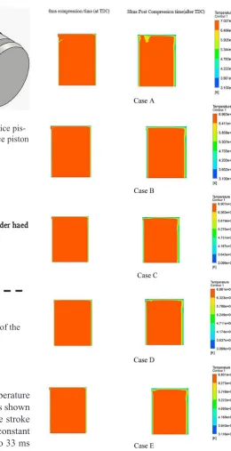
The thermal properties were created and specified as temperature dependent polynomials [23]. There are possibly two options to determine the piston profile for the simulation. First using raw experimental pressure trace data to derive the velocity of motion, as described by the previous author [18] and secondly, using the data from the LVDT displacement data, as illustrated in Fig 1. The displacement profile is relevant for the nu -merical calculation where it serves as an input file or used as a user-defined function for specifying the piston motion of the model.
The governing equations; the conservation of energy, momentum and mass were used to solve the model. The previous work had established that laminar flow model can adequately describe the experimental pressure history and veloc -ity field inside a rapid compression machine [8, 24, 25] on that juncture, the laminar flow model
was adopted for this simulation. For the pressure-velocity coupling, the segregated implicit solver with pressure-implicit split-operator (PISO) algo -rithm was more convenient [26]. Errors from the interpolation of the simulation were taken care of by implementing the pressure staggering option (PRESTO) and the pressure gradient assump -tions on boundaries are eventually avoided [27]. Therefore, for high body forces (swirl) problems, it is more recommended to handle such cases and for density and momentum, the second-order up -wind discretization was implemented [27]. The function of second order upwind scheme was to change the differential equation into an algebraic equation using Taylor series. However, the first order scheme is preferred because of its high ac -curacy but more computationally expensive.
Optimisation of Piston Crevice
Previous CFD work by the author [21, 22] revealed that the appropriate crevice volume that would contain the roll-up vortex for their RCM was 282 mm3, about 2% of the overall chamber
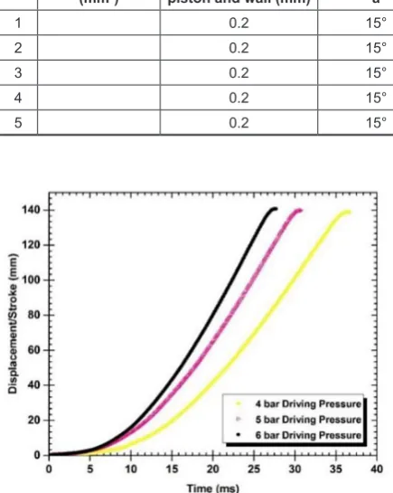
volume at the end of the stroke. This volume was then used as the starting volume for further opti -misation where five crevice lengths were tested. Table 1. shows the dimension of piston crevice volume with the chamfered head. In the design, the clearance between the combustion chamber and the piston was maintained at 0.2 mm to ac -commodate for thermal expansion of the mate -rials. The piston with the chamfered head was adopted from previous study [9], this design pre -vents gas flow in and out from the crevice to the chamber. For the present design an angle of 15° was maintained throughout the simulation. The distance through which the trapped gas travels plays a vital role in cooling the gas to avoid fur -ther chemical reaction occurring along the chan -nel length of the piston. Wurmel and Simmie [9] recommended a minimum channel length of 4 mm which was adopted for this modelling.
Fig. 1. Illustrate the LVDT piston displacement/ Stroke measurement for three different driving pres
-sures, 4, 5 and 6 bar
Table 1. Shows the dimensions of the optimised crevice piston height in mm
No. Crevice Volume (mm3) piston and wall (mm)Clearance between Inclined Angle, a Channel length, b (mm) Crevice length, c (mm) Height of Crevice, d (mm)
1 0.2 15° 4 2.53 3
2 0.2 15° 4 3.58 5
3 0.2 15° 4 4.39 7
4 0.2 15° 4 5.06 9
RESULTS AND DISCUSSION
Figure 4, shows the contours of temperature profiles for the simulation run for all cases shown in Table 1. 0 ms represents the end of the stroke where the reactor piston is brought to constant volume. The simulation was studied up to 33 ms post-compression time.
Crevice A, had the highest compressed gas temperature of 679.6 K but had cooling gases forcing their way back into the core region as the volume was not large enough to contain the cold gases.
Crevice B suppressed the roll-up vortex with the end of compressed pressure and achieved a temperature of 647 K and 19.5bar. Subsequent crevices (C, D, E) contained the vortex as shown in Figure 4, but a drastic reduction in the end gas pressure and temperature.
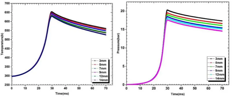
The optimised crevice piston was improved from the initial crevice volume of 282 mm3
through optimisation of the crevice height. The
result in Figure 5, shows that 5 mm height was found to be the best at improving the end gas pressure to about 2 bar. The end of gas pressure for a crevice height of 5 mm was 20.5 bar while that of 14 mm was 18.6 bar. Therefore, approxi -mately 2 bar was achieved by the varying the height of the crevice, while the corresponding end of the gas temperature s 17.7 K as shown in Figure 5.
Fig. 2. a). The diagram of the improved crevice pis
-ton, b). An isometric view of improved crevice piston
Fig. 3. A 2D computational grid at the end of the stroke
Fig. 4. The contour of the temperature profile for piston crevice head with varying height: a) 3 mm, b)
5 mm, c) 7 mm, d) 9 mm, e) 12 mm
CONCLUSION
The design of the crevice piston plays impor -tant roles in maintaining the temperature homo -geneity of the chamber. It also shows that having a larger crevice volume significantly reduces the end gas pressure and temperature. This was in -vestigated by carrying out an optimisation study on the crevice volume of 282 mm3. In the simu
-lation, a pressure gain of about 2 bar and a com -pressed gas temperature of 17.7 K was achieved from the optimisation of the piston crevice, which could have a considerable effect on the ignition delay of hydrocarbon fuels. It should be noted that while designing a crevice piston, consideration should be taken so that the crev -ice volume is not too large. Other procedures for improving the compressed gas pressure and tem -perature still exist, such as altering the compres -sion ratio, initial temperature, the initial pressure and using diluent gases. However, when these procedures are exhausted, an alternative means of improving the end gas pressure is to optimise the crevice volume in order to improve the end gas temperature and pressure.
Acknowledgements
I wish to acknowledge the Department of Mechanical Engineering of the University of Sheffield for funding the research project on the development of Rapid compression ma -chine. Not forgetting the unlimited effort of my technician, Mr Malcolm Nettleship, who has been supportive and always ready to take any responsibility during the design process of the experimental facility.
REFERENCES
1. Mittal, G. and Gupta, S., Computational assess
-ment of an approach for imple-menting crevice con
-tainment in rapid compression machines, Fuel, vol. 102, 2012, pp. 536-44.
2. Goldsborough, S. S., Banyon, C., and Mittal, G., A computationally efficient, physics-based model for simulating heat loss during compression and the delay period in RCM experiments, Combustion and Flame, vol. 159, 2012, pp. 3476-92.
3. Griffiths, J. F., Jiao, Q., Schreiber, M., et al., Devel
-opment of thermokinetic models for autoignition in a CFD Code: Experimental validation and appli
-cation of the results to rapid compression studies, Symposium (International) on Combustion, vol. 24, 1992, pp. 1809-15.
4. Desgroux, P., Gasnot, L., and Sochet, L. R., Instanta
-neous temperature measurement in a rapid-compres
-sion machine using laser Rayleigh scattering, Applied Physics B Laser and Optics, vol. 61, 1995, pp. 69-72. 5. Lee, D. and Hochgreb, S., Rapid compression ma
-chines: Heat transfer and suppression of corner vortex, Combustion and Flame, vol. 114, Aug-Sep 1998, pp. 531-45.
6. Griffiths, J. F., MacNamara, J. P., Mohamed, C., et al., Temperature fields during the development of autoignition in a rapid compression machine, Fara
-day Discussions, vol. 119, 2001, pp. 287-303. 7. Mittal, G. and Sung, C. J., Aerodynamics inside
a rapid compression machine, Combustion and Flame, vol. 145, 2006, pp. 160-80.
8. Mittal, G. and Sung, C.-J., Aerodynamics inside a rapid compression machine, Combustion and Flame, vol. 145, 2006, pp. 160-80.
9. Würmel, J. and Simmie, J. M., CFD studies of a twin-piston rapid compression machine, Combus
-tion and Flame, vol. 141, 2005, pp. 417-30.
10. Brett, L., Macnamara, J., Musch, P., et al., Simula
-tion of methane autoigni-tion in a rapid compres
-sion machine with creviced pistons, Combustion and Flame, vol. 124, 2001, pp. 326-29.
11. Lee, D. and Hochgreb, S., Rapid Compression Machines: Heat Transfer and Suppression of Corner Vortex, Combustion and Flame, vol. 114, 1998, pp. 531-45.
12. Park, P., Rapid compression machine measure
-ments of ignition delays for primary reference fu
-els, Massachusetts Institute of Technology, 1990. 13. Park, P. and Keck, J. C., Rapid compression ma
-chine measurements of ignition delays for primary reference fuels, SAE Technical Paper 1990. 14. Lee, D. and Hochgreb, S., Rapid compression ma
-chines: Heat transfer and suppression of corner vortex, Combustion and Flame, vol. 114, 1998, pp. 531-45. 15. Brett, L., MacNamara, J., Musch, P., et al., Simula
-tion of methane autoigni-tion in a rapid compres
-sion machine with creviced pistons, Combustion and flame, vol. 124, 2001, pp. 326-29.
16. Griffiths, J. F., Piazzesi, R., Sazhina, E. M., et al., CFD modelling of cyclohexane auto-ignition in an RCM, Fuel, vol. 96, 2012, pp. 192-203.
17. Mittal, G., A rapid compression machine – design, characterization, and autoignition investigations. Ph.D Thesis, Mechanical and Aerospace Engineer
-ing, Case Western Reserve University, Mechanical Engineering, 2006.
18. Mittal, G., Raju, M. P., and Sung, C.-J., Computa
-tional fluid dynamics modeling of hydrogen igni
-tion in a rapid compression machine, Combus-tion and Flame, vol. 155, 2008, pp. 417-28.
19. Mittal, G., Raju, M. P., and Sung, C.-J., CFD mod
-eling of two-stage ignition in a rapid compression
machine: Assessment of zero-dimensional ap
-proach, Combustion and Flame, vol. 157, 2010, pp. 1316-24.
20. Mittal, G., Raju, M. P., and Bhari, A., A numerical assessment of the novel concept of crevice contain
-ment in a rapid compression machine, Combustion and Flame, vol. 158, 2011, pp. 2420-27.
21. Nyong, O., Development of a Rapid Compression Machine for Screening Alternative Fuel for Gas Turbines, University of Sheffield, 2017.
22. Nyong, O., Woolley, R., Blakey, S., et al., Optimal piston crevice study in a rapid compression ma
-chine, in IOP Conference Series: Materials Science and Engineering, 2017, p. 012018.
23. Lemmon, E., McLinden, M., and Friend, D., Ther
-mophysical Properties of Fluid Systems in NIST Chemistry WebBook, NIST Standard Reference Database Number 69, Eds. Linstrom, PJ and Mal
-lard, WG, National Institute of Standards and Tech
-nology, Gaithersburg MD, 20899, webbook. nist. gov/chemistry/fluids (accessed April, 2015), 2011. 24. Goldsborough, S. S. and Potokar, C. J., The influence
of crevice flows and blow-by on the charge motion and temperature profiles within a Rapid Compres
-sion Expan-sion Machine used for chemical kinetic (HCCI) studies, SAE Paper, 2007, pp. 01-0169. 25. Mittal, G. and Chomier, M., Interpretation of experi
-mental data from rapid compression machines with
-out creviced pistons, Combustion and Flame, 2013. 26. Issa, R. I., Gosman, A. D., and Watkins, A. P., The
computation of compressible and incompress
-ible recirculating flows by a non-iterative implicit scheme, Journal of Computational Physics, vol. 62, 1986, pp. 66-82.