Please cite this article as: S. Gol, G. Ardeshir, M. Zahabi, A. Ale Ahmad, The Influence of DC-Link Voltage on the Commutation Torque Ripple of the Brushless DC Motors with Two-Segment Pulse-width Modulation Control Method,International Journal of Engineering (IJE),IJE TRANSACTIONS B: Applications Vol. 31, No. 2, (February 2018) 307-314
International Journal of Engineering
J o u r n a l H o m e p a g e : w w w . i j e . i rInfluence of DC-Link Voltage on Commutation Torque Ripple of Brushless DC
Motors with Two-Segment Pulse-width Modulation Control Method
S. Gol*, G. Ardeshir, M. Zahabi, A. Ale Ahmad
Faculty of Electrical and Computer Engineering, Babol Noshirvani University of Technology, Babol, Iran
P A P E R I N F O
Paper history:
Received 07November2017
Received in revised form 26November2017 Accepted 30November2017
Keywords:
Brushless DC Motors Motor Drive System Commutation Torque Ripple Pulse-width Modulation DC-link Voltage
A B S T R A C T
The commutation process causes current ripple to be generated in the drive system of brushless DC (BLDC) motor. This, in turn, leads to torque ripple that causes mechanical vibration and acoustic noise which are undesirable phenomenon in some applications. A new method is presented in this paper which reduces torque ripple and commutation period in the entire range of motor speed. This method is designed and implemented using two-segment pulse-width modulation (PWM) and DC-link voltage doubling during commutation. Based on the presented theory and given the influence of DC-link voltage on ripple magnitude, some experiments were carried out in which simultaneous contribution of the above mentioned factors in reducing current ripple and commutation time in the entire speed range of rotor are shown. The experimental results showed that the current ripple magnitude in high speed range is almost 20 times less than conventional method based on H-PWM_L-ON technique.
doi: 10.5829/ije.2018.31.02b.15
1. INTRODUCTION1
Brushless DC motors are extensively used in industrial applications such as electrical tools, compressor, and electrical vehicle system. This is due to high power density, reliable structure, low maintenance, and diversity of control methods from simple to advanced ones. On the other hand, the torque ripple in the output of brushless DC motors can prevent obtaining high performance. Therefore, some methods are required for its reduction or elimination.
The elimination of commutation torque ripple in the brushless DC motors with conduction angle of 120 electrical degrees could be possible by keeping current slope of outgoing and incoming phase in commutation period identical. This was shown mathematically and also demonstrated by simulation reported in literature [1]. One of the possible methods is using a proper mode of PWM. Some methods are proposed by research scientists [2, 3] in which in commutation period, incoming phase is turned on, and outgoing and non-commutation phases with the same duty cycle are turned
*Corresponding Author’s Email:[email protected](S. Gol)
inverter topology must be changed. Also, some factors such as PWM signal makes motor phases currents non-square and cause torque ripple to be appeared. Therefore in applications that mechanical vibration and acoustic noise are undesirable, this ripple must be eliminated.
In this paper, a method is proposed that in commutation interval, while dividing each PWM period into two segments, a voltage which is two times as that of phases conduction period, is applied to DC-link of three-phase inverter. The appropriate period for each of two segments can adjust the current slope of the outgoing and incoming phases in commutation period effectively and leads to elimination of the commutation torque ripple. Based on the equations resulted from the proposed method, the commutation process is controlled in such a way that the commutation period is minimized and the torque ripple is eliminated. The experimental results based on the proposed method using drive system of AK-ST7FMC showed that changing DC-link voltage in the commutation period reduces the torque ripple and the commutation period.
This paper’s structure is as follows: section 2 describes the origins of commutation torque ripple and provides some effective solutions for its elimination. Section 3, while describing the proposed method for ripple elimination, presents the mathematical analysis of the mentioned method. Section 4 is allocated to the experimental results based on conventional method [2, 4], and the proposed method as well. In addition, the deviation by changing DC-link voltage is investigated.
2. THE COMMUTATION TORQUE RIPPLE AND ITS ELIMINATION METHOD
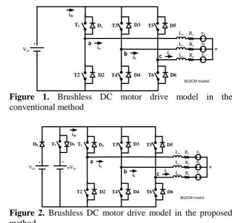
Figures 1 and 2 show brushless DC motor drive system model in conventional and proposed methods, respectively. In the proposed model, in addition to main power supply, another power supply with twice voltage and power far less than the main one is supplied. This power supply is connected to DC-link in commutation interval. Like the conventional model, each motor phase includes inductance, resistance, and back-electromotive force (BEMF) related to the winding of each phase. The wave form of BEMF of each phase is trapezoidal and the magnitude of its smooth section is equal to Em. If we
consider transition from ab to ac section in motor commutation period with six-step control method [9], in which non-commutation phase, outgoing phase, and incoming phase are a, b and c, respectively. The electromagnetic torque of motor is achieved by the following equation [1]:
𝑇𝑒=𝑒𝑎𝑖𝑎+ 𝑒𝜔𝑏𝑖𝑏+𝑒𝑐𝑖𝑐
𝑟 =
2𝐸𝑚.𝑖𝑎
𝜔𝑟 (1)
In which 𝜔𝑟, Te, ei, and ii (i=a, b, c) are angular velocity
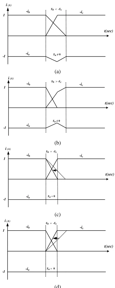
of the rotor, electromagnetic torque, BEMF, and phase current, respectively. Equation (1) states that electromagnetic torque waveform in commutation period is similar to the non-commutation phase current wave form. Therefore, by keeping non-commutation phase current constant, torque ripple would be eliminated. Figure 3 (a) and (b) show the reason for creation of commutation torque ripple. If brushless DC motor is considered in commutation time, the average absolute amount of the reduction slope of the outgoing current (|𝑠̅ |𝑏 ), is not equal with the average absolute amount of increasing slope of the incoming current
(|𝑠̅ |),𝑐 i.e., in Figure 3(a), |𝑠̅ | < |𝑠𝑏 ̅ |𝑐 , and in Figure
3(b), |𝑠̅ | > |𝑠𝑏 ̅ |𝑐 . The inequality of the reduction slope
of the outgoing phase current and increasing slope of the incoming phase current is the reason of creation of non-commutation phase current ripple, which in turn, is the reason of the existence of torque ripple in motor. For eliminating this ripple, an effective solution is to set the average slope of the non-commutation phase current to zero (𝑠̅ = 0𝑎 ) or equalizing the average slope of the
outgoing and incoming phase currents (𝑠̅ = −𝑠𝑏 ̅𝑐).
A more effective solution for eliminating torque ripple is to increase the slope which is slower between two slopes of outgoing and incoming phases (Figures 3(c) and 3(d)). Since commutation time is minimized by this method, which in turn, leads to smoother performance of the motor. Therefore, the idea of this work is the above mentioned solution, in which a method based on a two-segment PWM modulation along with doubling DC-link voltage of the three-phase inverter in the commutation interval is presented.
Figure 1. Brushless DC motor drive model in the
conventional method
Figure 2. Brushless DC motor drive model in the proposed
method
n
Vdc
T1
T2
T3
T4
T5
T6 D1
D2
D3
D4
D5
D6
a
b c
ea Ls Rs
eb Ls Rs
ec Ls Rs ia
ib ic
+
-idc
BLDCM model
n
Vdc
T1
T2
T3
T4
T5
T6 D1
D2
D3
D4
D5
D6
a
b c
ea
Ls Rs
eb
Ls Rs
ec
Ls Rs
ia
ib ic +
-+ - nVdc
T7 D7
D8
idc
Non-commutation phase: a
Incoming
phase: c t
Vg
Outgoing
phase: b t
t
Ts
d1 .Ts
(1-d1 )Ts
Segment S1 Segment S2
-ib -ic
-ia
sb < -sc I
-I i (A)
sa ≠ 0
t(sec)
(a)
-ib -ic
-ia
sb > -sc
I
-I
t(sec)
sa ≠ 0
i (A)
(b)
-ib -ic
-ia
sb = -sc
I
-I sa =
0
i (A)
t(sec)
(c)
-ib -ic
-ia
sb = -sc
I
-I sa =
0
i (A)
t(sec)
(d)
Figure 3. (a) and (b) The reason of creation of commutation
torque ripple (c) and (d) ripple elimination method.
3. The Fundamental of Two-Segment PWM Modulation Method
The proposed two-segment PWM modulation method is shown in Figure 4. In the conduction period of phases, the upper switches of the three-phase inverter in the brushless DC motor drive system with PWM signal and duty cycle (d) are modulated while in the commutation period, the non-commutation phase voltage is modulated with variable duty cycle. For example in transition from ab to ac section, the applied
Figure 4. PWM signal in the proposed method
PWM signal to T1 switch in a non-commutation phase
with d1 duty cycle, T4 switch in outgoing phase with 0%
duty cycle and T6 switch in incoming phase with 100%
duty cycles are adjusted.
Figure 5 shows the proposed two-segment modulation method in a PWM period. In addition, in commutation time, the applied voltage to DC-link is twice that of main power supply. Hence, T7 switch in the
proposed drive system (see Figure2) is turned on based on detection of the commutation time. Two segments of S1 and S2 in Figure 5 act as following. S1 segment
period is selected as equal to [(1-d1).Ts], so that enough
space is provided for commutation period regulation, in such a way that more commutation slope, the shorter (1- d1). The amount of S2 segment period is selected equal
to (d1Ts). This segment increases incoming phase
current slope. Higher rotor speed reuslted in bigger d1.
In fact, balancing current slopes of the outgoing and incoming phases, appropriate period should be selected for two segments of S1 and S2. Under this condition,
commutation torque ripple is eliminated. The two-segment proposed method can be used for entire range of rotor speed. Table 1 summarizes the involved switches and PWM signal duty cycles of them for six-step control method.
3.1. Period of Each Segment in a PWM Interval In this section, by considering brushless DC motor model and applied symbols in Figure 2, the proposed method is analyzed.
TABLE 1. Involved switches and their PWM signal duty cycle in the proposed method
Sector Duty Ratio ab ac ac bc bc ba ba ca ca cb cb ab
𝑑1 𝑇1 𝑇6 𝑇3 𝑇2 𝑇5 𝑇4
0 𝑇4 𝑇1 𝑇6 𝑇3 𝑇2 𝑇5
1 𝑇6 𝑇3 𝑇2 𝑇5 𝑇4 𝑇1
The terminal voltages of the windings of statorare obtained from the following equation:
𝑣𝑗= 𝐿𝑠 𝑑𝑖𝑗
𝑑𝑡+ 𝑅𝑠𝑖𝑗+ 𝑒𝑗+ 𝑣𝑛 ; 𝑗 = 𝑎, 𝑏, 𝑐 (2)
If, for example, we consider transition from ab to ac section in S1 segment from PWM interval in Table 1,
the circuit and current path of motor phases are according to Figure 6(a). In this segment, PWM signal is in off-state; hence, the upper and lower switches of the non-commutation phase, a, would be turned off; therefore, the stored energy in (La=Ls) inductance would
return to power supply through lower free wheeling diode, in such a way that ia current decreases. Also,
upper and lower switches of outgoing phase, b, are off; therefore, the stored energy in (Lb=Ls) inductance return
to power supply through upper free wheeling diode, hence, ib current decreases.
The lower switch of the incoming phase, c, is turned on; therefore, ic current increases slowly. Now, if we
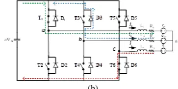
consider S2 segment from PWM interval, the circuit and
current path of motor phases are according to Figure 6(b). In this segment, PWM signal is on-state and upper switch of the non-commutation phase, a, is turned on; therefore, phase a is connected to the positive terminal of second power supply, hence, ia current increases. The
upper and lower switches of the outgoing phase, b, are turned off, hence, ib current decreases. The lower switch
of the incoming phase, c, is turned on, thus, a and c phases form a loop along with second power supply which leads to ic current increase.
To analyze the proposed method, based on Figure 6 the equivalent motor circuit and its drive system model are shown in Figure 7. The current slope of phases in the two segments of S1 and S2 can be obtained from
Kirchhoff law stated as follows:
(a)
(b)
Figure 6. Circuit and currents’ path in a PWM interval in
transition from ab to ac section a) for S1 segment. b) for S2
segment
(a) (b)
Figure 7. The equivalent circuit based on drive system
modeling in Figure 6 a) for S1 segment. b) for S2 segment
The current slope of the phases in S1 segment are:
𝑠𝑎|𝑆1= [𝑑𝑖𝑑𝑡𝑎]
𝑆𝑒𝑔−𝑆1= −𝑛
𝑉𝑑𝑐 3𝐿𝑠+
𝑒𝑏+𝑒𝑐−2𝑒𝑎
3𝐿𝑠 −
𝑖𝑎.𝑅𝑠 𝐿𝑠
𝑠𝑏|𝑆1= [ 𝑑𝑖𝑏
𝑑𝑡]𝑆𝑒𝑔−𝑆1= 2𝑛
𝑉𝑑𝑐 3𝐿𝑠+
𝑒𝑎+𝑒𝑐−2𝑒𝑏
3𝐿𝑠 −
𝑖𝑏.𝑅𝑠 𝐿𝑠
𝑠𝑐|𝑆1= [ 𝑑𝑖𝑐
𝑑𝑡]𝑆𝑒𝑔−𝑆1= −𝑛
𝑉𝑑𝑐 3𝐿𝑠+
𝑒𝑎 + 𝑒𝑏−2𝑒𝑐
3𝐿𝑠 −
𝑖𝑐.𝑅𝑠 𝐿𝑠
(3)
Also, the current slopes in S2 segment are:
𝑠𝑎|𝑆2= [ 𝑑𝑖𝑎
𝑑𝑡]𝑆𝑒𝑔−𝑆2= 𝑛 𝑉𝑑𝑐 3𝐿𝑠+
𝑒𝑏+𝑒𝑐−2𝑒𝑎
3𝐿𝑠 −
𝑖𝑎.𝑅𝑠 𝐿𝑠
𝑠𝑏|𝑆2= [ 𝑑𝑖𝑏
𝑑𝑡]𝑆𝑒𝑔−𝑆2= 𝑛 𝑉𝑑𝑐 3𝐿𝑠+
𝑒𝑎+𝑒𝑐−2𝑒𝑏
3𝐿𝑠 −
𝑖𝑏.𝑅𝑠 𝐿𝑠
𝑠𝑐|𝑆2= [ 𝑑𝑖𝑐
𝑑𝑡]𝑆𝑒𝑔−𝑆2= −2𝑛
𝑉𝑑𝑐 3𝐿𝑠+
𝑒𝑎 + 𝑒𝑏−2𝑒𝑐
3𝐿𝑠 −
𝑖𝑐.𝑅𝑠 𝐿𝑠
(4)
Based on the above equations, current slopes in two segment of S1 and S2 are unequal. To make equal the
slope of outgoing and incoming currents, we need to allocate an appropriate portion to each of them in each segment. For this purpose, the slopes of currents are calculated as follows.
S1 and S2 segments in an interval are considered by
the (1-d1) and d1 cooperation level, respectively. Hence
we have:
𝑠̅ = [𝑎 𝑑𝑖𝑎
𝑑𝑡] ̅̅̅̅̅̅
= (1 − 𝑑1) [ 𝑑𝑖𝑎
𝑑𝑡]𝑆𝑒𝑔−𝑆1+ 𝑑1[ 𝑑𝑖𝑎
𝑑𝑡]𝑆𝑒𝑔−𝑆2
𝑠̅ = [𝑎 𝑑𝑖𝑎
𝑑𝑡] ̅̅̅̅̅̅
= (1 − 𝑑1) (−𝑛
𝑉𝑑𝑐
3𝐿𝑠) + 𝑑1(𝑛 𝑉𝑑𝑐
3𝐿𝑠) + 𝑒𝑏+𝑒𝑐−2𝑒𝑎
3𝐿𝑠 −
𝐼.𝑅𝑠 𝐿𝑠 (5) n eb Ls Rs
ea Ls Rs
ec Ls Rs ib ia ic nVdc + + + -+ - n eb Ls Rs
ea Ls Rs
-On the other hand, regarding 3-phase brushless DC motors, we can write:
𝑒𝑎 = − 𝑒𝑏 = −𝑒𝑐 = 𝐸𝑚 (6)
Therefore, Equation (5) can be written as:
𝑠̅ = [𝑎 𝑑𝑖𝑎
𝑑𝑡] ̅̅̅̅̅̅
= 2𝑑1(𝑛
𝑉𝑑𝑐 3𝐿𝑠) − (𝑛
𝑉𝑑𝑐 3𝐿𝑠) −
4𝐸𝑚 3𝐿𝑠−
𝐼.𝑅𝑠
𝐿𝑠 (7)
Similarly for [𝑑𝑖𝑏
𝑑𝑡]
̅̅̅̅̅̅ and [𝑑𝑖𝑐
𝑑𝑡]
̅̅̅̅̅̅
we have:
𝑠̅ = [𝑏 𝑑𝑖𝑏
𝑑𝑡] ̅̅̅̅̅̅
= (1 − 𝑑1) [ 𝑑𝑖𝑏
𝑑𝑡]𝑆𝑒𝑔−𝑆1+ 𝑑1[ 𝑑𝑖𝑏
𝑑𝑡]𝑆𝑒𝑔−𝑆2
𝑠̅ = [𝑏 ̅̅̅̅̅̅𝑑𝑖𝑑𝑡𝑏]= (1 − 𝑑1) (2𝑛𝑉3𝐿𝑑𝑐
𝑠) + 𝑑1(𝑛 𝑉𝑑𝑐 3𝐿𝑠) + 𝑒𝑎+𝑒𝑐−2𝑒𝑏
3𝐿𝑠 +
𝐼.𝑅𝑠 2𝐿𝑠
𝑠̅ = [𝑏 𝑑𝑖𝑏
𝑑𝑡] ̅̅̅̅̅̅
= 2 (𝑛𝑉𝑑𝑐 3𝐿𝑠) − (𝑛
𝑉𝑑𝑐 3𝐿𝑠) 𝑑1+
2𝐸𝑚 3𝐿𝑠+
𝐼.𝑅𝑠 2𝐿𝑠
(8)
and
𝑠̅ = [𝑐
𝑑𝑖𝑐
𝑑𝑡]
̅̅̅̅̅̅
= (1 − 𝑑1) [
𝑑𝑖𝑐
𝑑𝑡]𝑆𝑒𝑔−𝑆1+ 𝑑1[
𝑑𝑖𝑐
𝑑𝑡]𝑆𝑒𝑔−𝑆2
𝑠̅ = [𝑐
𝑑𝑖𝑐
𝑑𝑡]
̅̅̅̅̅̅
= (1 − 𝑑1) (−𝑛
𝑉𝑑𝑐
3𝐿𝑠) + 𝑑1(−2𝑛
𝑉𝑑𝑐
3𝐿𝑠) +
𝑒𝑎+𝑒𝑏−2𝑒𝑐
3𝐿𝑠 +
𝐼.𝑅𝑠
2𝐿𝑠
𝑠̅ = [𝑐
𝑑𝑖𝑐
𝑑𝑡]
̅̅̅̅̅̅
= − (𝑛𝑉𝑑𝑐
3𝐿𝑠) − (𝑛
𝑉𝑑𝑐
3𝐿𝑠) 𝑑1+
2𝐸𝑚
3𝐿𝑠+
𝐼.𝑅𝑠
2𝐿𝑠
(9)
Based on the above equations, for eliminating commutation torque ripple, it is necessary to have:
𝑠̅ = 0 𝑜𝑟 𝑠𝑎 ̅ = −𝑠𝑏 ̅𝑐 (10)
Therefore:
2𝑛. 𝑑1= 𝑛 + 4𝐸𝑚
𝑉𝑑𝑐+ 3𝐼.𝑅𝑠
𝑉𝑑𝑐 (11)
On one hand, at steady state, according to PWM technique, we have:
𝑑. 𝑉𝑑𝑐= 2(𝐼. 𝑅𝑠+ 𝐸𝑚) (12)
whered is PWM’s duty cycle.
Using Equations (11) and (12) we obtain:
𝑑1=
1
2+
𝑑
𝑛−
𝐼.𝑅𝑠
2𝑛𝑉𝑑𝑐 (13)
Therefore, commutation torque ripple is eliminated if Equation (13) is satisfied. In practical situations, the last term of Equation (13) is ignored due to low resistance (Rs) of windings. On the other hand, for duty cycle we
have 0≤d≤1. Also, according to Equation (13) n=2 is the best value to avoid the issues regarding maximum insulation voltage of the motor and electric break down of IGBT switches. Since 0≤d≤1 and n=2, we obtain 0.5≤d1≤1 by ignoring the last term in Equation (13).
4. EXPERIMENTAL RESULTS
For evaluating the proposed method, some experiments were carried out for investigating the influence of
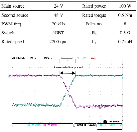
DC-link voltage on commutation torque ripple. The experiment set-up specifications are summarized in Table 2. In the experimental set-up, DC generator acts as a load. In commutation interval, the outgoing and incoming phase current obtained by the proposed method are shown in Figure 8. As it can be seen in this figure, the slopes of the currents were defined as equal.
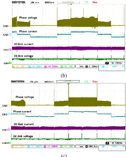
Given the fact that ripple magnitude of phase current and also, torque has an inverse relationship with PWM frequency, increasing of this frequency is desired. On the other hand, since PWM maximum frequency in AK-ST7FMC control board is 20 KHz, this frequency was selected in all experiments. Also, coefficient of current probe is set to 100 mv/A condition. Figure 9(b) shows voltage and current signals of motor phase and DC-link for the proposed method with d=0.3, d1=0.65. Main
power supply voltage is Vdc=24V. Therefore, the second
power supply is 48V. In this figure, phase a voltage, phase a current, DC-link current and voltage are shown from top to bottom, respectively. As it can be seen, current ripple is small. For demonstrating the influence of the second source voltage oncommutation current ripple, its value was deviated as ±12V (±25%) compared to twice of phases voltages during conduction time.
Illustrations in Figures 9(a) and (c), current ripple increases in these situations compared to Figure 9(b). Figure 10 shows the above mentioned wave forms for d=0.6 and d1=0.8 for three supply voltages in
commutation period (36V, 48V, and 60V). As it can be seen, current ripple increases when DC-link voltage is not twice.
TABLE 2. Drive and motor specifications
Figure 8. Outgoing and incoming phases current in
commutation for d=0.9, d1=0.95 and 4A phase current
Main source 24 V Rated power 100 W
Second source 48 V Rated torque 0.5 Nm
PWM freq. 20 kHz Poles no. 8
Switch IGBT Rs 0.3 Ω
Rated speed 2200 rpm Ls 0.7 mH
Figure 11 shows waveforms for d=0.9 and d1=0.95.
According to this figure, it can be observed that the results are the same as for other values of d. We can conclude that the proposed method acts for entire range of rotor speed very well.
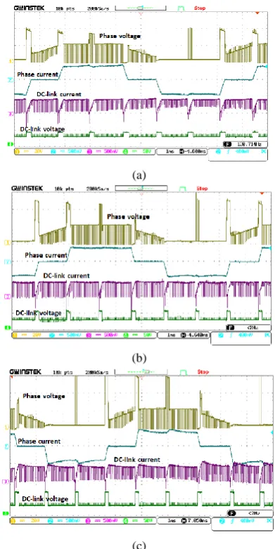
For investigating the reduction of current ripple and commutation period, some experiments were carried out with conventional method based on common technique of H-PWM_L-ON. Figure 12 shows experimental results where the PWM duty cycle is 0.3, 0.6, and 0.9, respectively. Tables 3 and 4 summarize extracted numerical information from Figures 9-12 for comparing the conventional method with the proposed method.
TABLE 3. Current ripple in conventional and proposed
methods Duty Cycle (d) Measured Current Ripple
30% 60% 90%
Proposed method
36V ≃20% ≃20% ≃20%
48V ≃2% ≃2% ≃2%
60V ≃30% ≃30% ≃30%
H-PWM_L-ON method ≃50% ≃50% ≃50%
TABLE 4. Commutation period in the proposed and
conventional methods
Duty Cycle (d) Measured
Commutation Period
30% 60% 90%
Proposed method ≃60μs ≃90μs ≃120μs
H-PWM_L-ON method ≃300μs ≃300μs ≃300μs
(a)
(b)
(c)
Figure 9. Experimental signals in the proposed method for
24V, d=0.3, and d1=0.65, supply voltage source regulation in
a) 36 volts, b) 48V, and c) 60V states. Each segment’s signals from top to bottom, phase voltage, phase current, DC-link current and voltage, respectively
(a)
(c)
Figure 10. Experimental signals in the proposed method for
24V, d=0.6, and d1=0.8, supply voltage source regulation in a)
36 volts, b) 48V, and c) 60V states. Each segment’s signals from top to bottom, phase voltage, phase current, DC-link current and voltage, respectively
(a)
(b)
(c)
Figure 11. Experimental signals in the proposed method for
24 volts, d=0.9, and d1=0.95, supply voltage source regulation
in a) 36V, b) 48V, and c) 60V states. Each segment’s signals from top to bottom, phase voltage, phase current, DC-link current and voltage, respectively
(a)
(b)
(c)
Figure 12. Experimental signals in the conventional method
based on H-PWM_L-ON technique for 24V supply voltage in a) d=0.3, b) d=0.6 and c) d=0.9 states. Each segment’s signals
from top to bottom, phase voltage, phase current, DC-link current and voltage, respectively
5. CONCLUSION
6. REFERENCES
1. Carlson, R., Lajoie-Mazenc, M. and Fagundes, J., "Analysis of torque ripple due to phase commutation in brushless dc machines", IEEE Transactions on Industry Applications, Vol. 28, No. 3, (1992), 632-638.
2. Lin, Y.-K. and Lai, Y.-S., "Pulsewidth modulation technique for bldcm drives to reduce commutation torque ripple without calculation of commutation time", IEEE Transactions on
Industry Applications, Vol. 47, No. 4, (2011), 1786-1793.
3. Lu, H., Zhang, L. and Qu, W., "A new torque control method for torque ripple minimization of bldc motors with un-ideal back emf", IEEE Transactions on Power Electronics, Vol. 23, No. 2, (2008), 950-958.
4. Shi, T., Guo, Y., Song, P. and Xia, C., "A new approach of minimizing commutation torque ripple for brushless dc motor based on dc–dc converter", IEEE Transactions on Industrial
Electronics, Vol. 57, No. 10, (2010), 3483-3490.
5. Fang, J., Zhou, X. and Liu, G., "Precise accelerated torque control for small inductance brushless dc motor", IEEE
Transactions on Power Electronics, Vol. 28, No. 3, (2013),
1400-1412.
6. Xia, C., Xiao, Y., Chen, W. and Shi, T., "Torque ripple reduction in brushless dc drives based on reference current optimization using integral variable structure control", IEEE
Transactions on Industrial Electronics, Vol. 61, No. 2, (2014),
738-752.
7. Shi, J. and Li, T.-C., "New method to eliminate commutation torque ripple of brushless dc motor with minimum commutation time", IEEE Transactions on Industrial Electronics, Vol. 60, No. 6, (2013), 2139-2146.
8. Xu, Y., Wei, Y., Wang, B. and Zou, J., "A novel inverter topology for brushless dc motor drive to shorten commutation time", IEEE Transactions on Industrial Electronics, Vol. 63, No. 2, (2016), 796-807.
9. Shao, J., Nolan, D., Teissier, M. and Swanson, D., "A novel microcontroller-based sensorless brushless dc (bldc) motor drive for automotive fuel pumps", IEEE Transactions on Industry
Applications, Vol. 39, No. 6, (2003), 1734-1740.
The Influence of DC-Link Voltage on Commutation Torque Ripple of Brushless DC
Motors with Two-Segment Pulse-width Modulation Control Method
S. Gol, G. Ardeshir, M. Zahabi, A. Ale Ahmad
Faculty of Electrical and Computer Engineering, Babol Noshirvani University of Technology, Babol, Iran
P A P E R I N F O
Paper history:
Received 07November 2017
Received in revised form 26November 2017 Accepted 30November 2017
Keywords:
Brushless DC Motors Motor Drive System Commutation Torque Ripple Pulse-width Modulation DC-link Voltage
ديكچ ه
هار هناماس رد نایرج نابرض شیادیپ ببس نویساتومک دنیآرف روتوم زادنا
DC
یم کبوراج نودب دوخ هبون هب نیا .دوش
یم یجورخ رواتشگ ناسون هب رجنم هدیدپ اهدربراک زا یخرب رد هک هدوب نآ راثآ زا یتوص زیون و یکیناکم شزرل .ددرگ
یا
یم هئارا یدیدج شور هلاقم نیا رد .تسا بولطمان تّدم و رواتشگ نابرض هک دوش
هدودحم لک رد ار نویساتومک نامز
یم شهاک روتوم تعرس کنیل ژاتلو ندومن ربارب ود و یتمسق ود سلاپ یانهپ نویسلاودم ساسا رب شور نیا .دهد
DC
رد
هدایپ و یحارط نویساتومک هزاب نبم رب .تسا هدش یزاس
،نابرض هنماد رب هیذغت ژاتلو ریثات هب هجوت اب و هدش هئارا یروئت یا
تّدم و نایرج نابرض شهاک رد نامزمه روطب روکذم لماع ود تکراشم هک دش ماجنا یتاشیامزآ رد نویساتومک نامز
ودحم رد نایرج نابرض هنماد هک تسا هداد ناشن تاشیامزآ جیاتن .دش تابثا روتور تعرس عیسو هدودحم دایز تعرس هد
ًابیرقت 20 رب ینتبم لوادتم شور زا رتمک ربارب کینکت
H-PWM_L-ON
یم .دشاب