264
Volume-4, Issue-4, August-2014,
ISSN No.: 2250-0758
International Journal of Engineering and Management Research
Available at:
www.ijemr.net
Page
Number:
264
-
268
Review of Different Structure and application of Microstrip Patch
Antenna
Manoj Thakur1, Vikram Pratap singh2
1,2Department of Electronics and Communication Engineering, INDIA
ABSTRACT
The demand in wireless communication is changing frequently and microstrip patch antenna plays a key role in wireless service requirement. In wireless communication, there are lots of areas, but two of them changes very rapidly, such as mobile devise and computers. They are always working on flexibility, reliability, cost effective and high speed data connectivity and user mobility. This paper presents a literature survey of single, dual band rectangular patch antenna with different feeding technique and a variety of substrates. In this paper, we also discuss the basics of microstrip patch antennas, parameters and various feeding techniques and their advantage and disadvantage
Keywords- Microstrip Patch Antenna, Antenna parameters, feed technique, Dielectric constant, Antenna type.
I.
I
NTRODUCTIONIn wireless communication antennas play a very important role. There are so many types of antennas in which some of them are parabolic reflectors, slot antennas, folded dipole antennas and patch antennas. All of them having different properties and usage. By comparing with the conventional antennas, microstrip patch antenna has more advantage and better prospects. The key feature of a microstrip patch antennas is low cost, light weight, low profile, ease to fabricate and conformal to the mounting surface. These types of characteristics make them popular in many wireless communication applications such as WLAN/WiMAX, satellite communication etc.
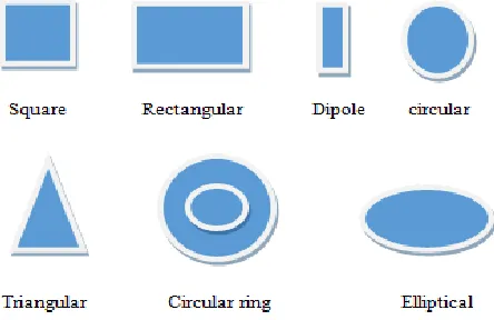
Microstrip patch antenna substrate consists two main side one is radiating patch and other side of the substrate is a ground plane as shown in figure 1. The patch of antenna is generally made of conducting material such as copper or gold and can take any desirable shape like square, rectangular, dipole, circular, triangular, circular ring and elliptical etc. This radiating patch is usually photo etched on the dielectric substrate and it radiates due to the fringing field effect between the patch and the ground plane. In the case of contacting method, the RF power is directly fed to radiating patch with the use of connecting element, such as a microstrip probe feed or line feed. A better antenna performance is
attained by choosing a thick dielectric substrate having a low dielectric constant, good feeding technique with perfect Impedance matching. This provides greater efficiency, larger bandwidth and better radiation pattern. We can say that antenna performs well if it’s VSWR≤2 and return loss RL≥-9.5dB
Figure 1 Structure of a Microstrip Patch Antenna
265
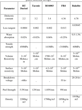
The dielectric substrates used in microstrip patch
antennas are Rogers RT/duroid5870 (tm), FR4 Glass Epoxy, Taconic TLC, RO4003 and Bakelite. The height of the substrates is constant 1.5 mm. Different parameters such as Return Loss, VSWR, Antenna Gain, Antenna Efficiency, Directivity, and Bandwidth is analyzed
PROPERTIES OF DIELECTRIC SUBSTRATES 1. Rogers RT Duroid
RT Duroid 5870 is produced by Roger Corporation. It is a Glass Microfiber Reinforced PTFE (Polytetrafluoroethylene) composite. RT Duroid 5870 substrate have low loss tangent, ease of fabrication, cutting, shearing, machining, excellent chemical resistance, including solvent and reagents used in printing and plotting.
2. FR-4 or (FR4) Gloss Epoxy
FR-4 glass epoxy is a famous and changeable high pressure thermo set plastic laminate grade with good strength to weight ratios. It is most commonly used as electrical insulator. It is composed of a composite material of woven fiberglass cloth with an epoxy resin binder that is self-extinguishing.
3. Taconic TLC
Taconic is specifically designed for Low cost objectives for newly emerging commercial RF/microwave applications. Materials exhibit excellent mechanical and thermal stability and cost less than Traditional PTFE substrates.
4. RO4003
The High Frequency Circuit Materials are glass Reinforced hydrocarbon/ceramic laminates (Not PTFE) Designed for performance sensitive, high volume commercial Applications. It has low cost circuit Fabrication, result low loss material which can be fabricated using standard epoxy/glass (FR4) processes offered at competitive prices.
5. Bakelite
Bakelite or polyoxybenzylmethylenglycolanhydride, is an Early plastic. It is mostly used as an electrical insulator possessing considerable mechanical strength. It is a thermosetting phenol formaldehyde resin, formed from an elimination reaction of phenol with formaldehyde.
TABLE 1 Properties of different substrates for microstrip patch antenna design
Parameter
RT Duriod
Taconic RO4003 FR4 Bakelite
Dielectric
constant 2.2 3.2 3.4 4.36 4.78
Loss tangent 0.0004 0.002 0.002 0.013
0.03045
Water
absorption 0.02% <0.02% 0.06% <0.25%
0.5-1.3%
Tensile
strength 450MPa - 141MPa <310MPa 60MPa
Volume Resistivity
2×10⁷ Mohm.c
m
1×10⁷ Mohm
.cm
1700×107 Mohm .cm
8×10⁷ Mohm.cm
3×10¹⁵ Mohm.
cm
Surface resistivity
3×10⁷ Mohm
1×10⁷ Mohm
4.2×10⁹ Mohm
2×10⁵ Mohm
5×10¹⁰ Mohm
Breakdown
voltage >60kv - - 55 kv
20-28 kv
Peel Strength 5.5N/nm 12N/nm 1.05N/nm 9N/nm -
Density 2200kg/
m3 -
1790kg/m3 1850kg/m
3
1810kg/ m3
II.
LITERATURE SURVEY
266
For vehicle applications patch antenna on glass wasintroduced by L. Economouetal [1]. 10% to 20% of the surface waves were excited by the glass laminated superstate. The change in bandwidth and resonant frequency became more uncertain due to the use of patches and microwave circuit within the glass laminate. It poses a bigger challenge for microstrip antennas on automotive glass where bandwidth requirement is 5% or more.
To rectify the problem microstrip patch antennas with a double L slot with CPW technology [2] is proposed for microwave and wireless communication application. It results in antennas with improved Omni directions characteristics and compact size for the frequencies to be used. For 3.5GHz, gain higher than 3dBi can be observed.
Small Printed Antenna design and its performance are presented by Waterhouse et al. In [3]. In this paper, electrically small microstrip patches comprising shorting posts are thoroughly investigated. These antennas are suitable for mobile communications handsets where limited antenna size is a premium. In this Techniques the antenna performance improves with the enhance of bandwidth. Paper present valuable insight to the optimum design, namely broad bandwidth, small size, and ease of manufacturing.
Dual band WLAN application of microstrip patch antenna [4] are proposed by Bharath Kelothu, K.R. Subhashini. In the paper a dual band L-shaped Microstrip patch antenna is printed on a FR-4 substrate for WLAN systems, and found a frequency range from 5.0GHz to 6.0 GHz with maximum gain of 8.4 and 7.1 dB at lower and higher frequency bands respectively.
A microstrip slot antenna [5] fed by a microstrip line has been proposed in this paper.
In
this paper bandwidth of the antenna has been improved and it used for WLAN and satellite application.Broadband microstrip patch antennas for MMICs is presented by Rowe et al. [6]. The stacked antenna consists of a 50Ω microstrip feed line and a patch element fabricated on alumina substrate which emulates the high dielectric constant materials used in MMICs. The parasitic patch elements are etched in Rogers RT/duroid 58880 laminates and are separated by form dielectrics. Good efficiency, a broad impedance bandwidth and large front to back ratio eliminates the need for cavities or other structures to reduce back radiation.
A Thin Internal GSM/DCS Patch Antenna for portable mobile terminal applications is presented by K.L. Wong et al. [7] The antenna incorporates a small portion of the top patch beyond the top edge of the system ground plane of the mobile terminal, which results enhanced bandwidths of the two resonant modes for covering the GSM and DCS bands.
A compact vertical patch antenna for dual band WLAN operation is presented by F.S. Change et al. [8]. The
antenna consists mainly of one driven patch and one shorted parasitic patch, both of which wind along two concentric circles. The antenna can be quite practical in applications of ceiling-mount access points.
In this paper [9] various feeding techniques are described. A circular polarized patch antenna of a shape similar to an alphabet “I” on FR4 substrate for BLUETOOTH applications has been examined. This paper describes a good impedance matching condition between the line and the patch without any additional matching elements.
III.
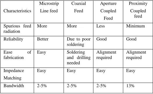
FEEDING TECHNIQUES
A feed is used to excite to radiate by direct or indirect contact. The feed of microstrip antenna can have many configurations like microstrip line, coaxial, aperture coupling and proximity coupling. But the microstrip line and the coaxial feeds are relatively easier to fabricate. The coaxial probe feed is used because it is easy to use and the input impedance of the coaxial cable in general is 50 ohms. There are several points on the patch which have 50 ohm impedance. We have to find out those points and match them with the input impedance. These points are found out through a mathematical model.
TABLE 2: comparing the different feeding techniques
Characteristics
Microstrip Line feed
Coaxial Feed
Aperture Coupled Feed
Proximity Coupled
feed
Spurious feed radiation
More More Less Minimum
Reliability Better Due to poor
soldering
Good Good
Ease of
fabrication
Easy Soldering
and drilling needed
Alignment required
Alignment required
Impedance Matching
Easy Easy Easy Easy
Bandwidth 2-5% 2-5% 2-5% 13%
IV.
ANTENNA PARAMETERS
There are Different type of parameter in antennas such as VSWR, Return Loss, Antenna Gain, Directivity, Antenna Efficiency and Bandwidth is analyzed.
267
(b) Radiation pattern: - The radiation pattern is a function
of mathematical and graphical representation of the radiation properties of the antenna as a function of space coordinates.
(c) Antenna efficiency: - It is defined as the ratio of total power radiated by an antenna to the input power of an antenna.
(d) VSWR: - it is defined as the ratio of VSWR=Vmax/V
min. In the ideal case it should be 1 and for better antenna performance the vswr value should be VSWR≤2
The VSWR is always a real and positive number for antennas. As smaller the VSWR value, the better the antenna is matched to the transmission line and the more power is delivered to the antenna
(e)
Return loss: - Return Loss is the power loss in the signal form which returned or reflected by a discontinuity in a transmission line or optical fiber. This discontinuity can be a mismatch with the terminating load or with a device insertedin the line. It is expressed as a ratio in decibels (dB).
Where RL (dB) is the return loss , Pi is the incident
power and Pr is the reflected power. Return loss is related to
both standing wave ratio (SWR) and reflection coefficient (Γ). Increasing the return loss, lower the SWR. Return loss is a measure of how well devices or lines are matched. If the return loss is high mean match is good. A high return loss means lower insertion loss.
RL = -20log |Г| (dB)
V.
ANTENNA DESIGN
To design the rectangular microstrip patch antenna some parameters and physical dimensions of the patch are calculated by following formulas.
Width: The width of the patch can be calculated from the following equation
Where fo is the resonant frequency, ℇr dielectric substrate
constant and m/s speed of light
Length: The length of the patch can be calculated from the
following equation.
Where ∆L and Leff are the extended length and
effective length due to fringing effects between patch and field. These values are calculated using following formulas as
Effective dielectric constant
The effective dielectric constant (εreff) is always less than (εr) due to the fringing field around the periphery of the patch is not confined to the dielectric speared in the air also. Its value is calculated as by formulas:-
VI.
ADVANTAGE AND DISADVANTAGE
The Microstrip patch antenna has several advantages over conventional microwave antenna with one similarity of frequency range from 100 MHz to 100 GHz same in both types. The various advantages and disadvantage are given in table 3.
Table 3: Advantage and disadvantage of patch antenna
Sr.No. Advantage Disadvantage
1 Low profile Low gain
2 Low weight Low efficiency
3 Thin profile Large ohmic loss in the feed
structure of arrays
4 Feed lines and matching
network can be fabricated simultaneously
Complex feed structure required high performance arrays
5 Capable of dual and triple frequency operation
Polarization purity is difficult to achieve
6 Linear and circular
polarization
Excitation of surface wave
7 Required no cavity backing
Low power handling capacity
268
VII. CONCLUSION
In this paper the theoretical survey on microstrip is presented. After study of various research papers it is concluded that the problem of narrow bandwidth, lower gain, low efficiency are overcome through an array configuration and by choosing low dielectric substrate constant. Feeding technique also impotent. The overall feeding technique comparison concludes that microstrip line feed has more advantage than other like easy impedance matching, low cost. But only 2-5% of the bandwidth is archived on line fed, it can enhanced by increasing the height of patch, increasing the substrate thickness and decreasing the permittivity of substrate.
R
EFERENCES[1]L. Economou and R.J. Langley, “ Circular microstrip patch antennas on Glass for vehicle applications”, IEE Proc. Microwave, Antennas and Propag. , Vol.345, No.5, pp. 416-421, 1998.
[2] R. Jothi Chitra,V. Nagarajan, 2013. “Double L-slot microstrip patch Antenna array for WiMAX and WLAN applications”, IEEE Transactions On Antennas and Propagation, Vol. 39, pp 1026-1041.
[3] Rod B. Waterhouse, S. D. Targonski, and D. M. Kokotoff, “Design and Performance of Small Printed Antennas”, VOL. 46, NO. 11, pp. 1629- 1633, 1998.
[4] Bharath Kelothu, K.R. Subhashini, IEEE Transactions 2012.“A compact High-gain microstrip patch antenna for dual band WLAN application”.
[5] Xu-bao Sun ,Mao-Young Cao, 2012. “A rectangular slot With Transactions improved bandwidth”, Elsevier Science Direct, Vol. 66, pp 465-466.
[6] W.S.T. Rowe and R.B. Waterhouse, “ Broadband microstrip patch Antennas for MMICs”, IEE Electronics letters, Vol. 36, No.7, pp. 597- 598, 2000.
[7] Kin-Lu Wong, Yuan- Chih Lin, and Ting-Chih Tseng, “Thin Internal GSM/DCS Patch Antenna for a Portable Mobile Terminal”, IEEE Transactions on Antennas and Propagation, Vol. 54, No. 1, pp. 238-241, 2006
[8] 0 F.-S. Chang, K.-C. Chao, C.-H. Lu and S.-W. Su, Compact vertical Patch antenna for dual-band WLAN operation, IEE Electronics Letters, Vo.44, No.10, 2008. [9] Govardhani Immadi, M.S.R.S Tejaswi, 2011. “Design of coaxial fed Microstrip patch antenna for 2.4 GHz Bluetooth Applications”, Journal of Emerging trends in computing and information sciences, Vol.2, pp 686- 690.