Wind Sensor W-RS485
with RS485 Interface
Technical data
and notes for installation
Description
The W-RS485 Wind Sensor measures wind speed and sends the currently recorded measured value once every second. This data flow can be received and analyzed by an end device such as SPS, PC or MC.
The W-RS485 has four connections. Data output is at terminals A and B. Terminals 1 and 2 are for the power supply (24 V DC). The connections are not resistant to pole reversal. Connecting them incorrectly will destroy the interface components.
Functions:
• Wind speed measurement by means of a nonwearing electronic sensor. No damage from storm or hail as with mechanical anemometers
Technical data
Housing: Plastic material
Colour: White / translucent
Mounting: On-wall
Protection category: IP 44
Dimensions: approx. 96 x 77 x 118 (W x H x D, mm)
Weight: approx. 160 g
Ambient temperature: Operation -30…+50°C, storage -30…+70°C Operating voltage: 24 V DC
Current: max. 105 mA, residual ripple 10%
Data output: RS485
Measurement range wind: 0…70 m/s
Resolution: <10% of the measured value Accuracy: ± 25% at 0…15 m/s,
at an angle of attack of 45°, pole mounting
The following standards were referenced with regard to evaluating electromagnetic compatibility of the product:
• EN 60730-1:2000-11 + A11:2002
The product has been tested by an accredited EMC laboratory according to the abovementioned standards.
PCB layout
Fig. 1
1 Socket for connection
1: +24 V DC | 2: GND | A: Data | B: Data
Transfer protocol
All characters and/or digits are based on the ASCII standard, i.e. every reading processed internally as an integer or float value will always be broken down into and transferred in its individual ASCII format characters. They must then be reassembled in the reverse process by the receiver.
Transfer rate: 19200 Baud Data bits: 8
Stop bit: 1
Byte No. Char Meaning
1 W Weather data start
2-16 – –
17 Wind: 1st digit Wind 1st digit (tens) 18 Wind: 2nd digit Wind 2nd digit (ones)
19 Wind: Point Wind Point
20 Wind: 3rd digit Wind 3rd digit (tenth)
21-35 – –
36 Checksum: 1st digit Checksum 1st digit (thousands) 37 Checksum: 2nd digit Checksum 2nd digit (hundreds) 38 Checksum: 3rd digit Checksum 3rd digit (tens) 39 Checksum: 4th digit Checksum 4th digit (ones)
40 End End 0x03
Installation and commissioning
The sensor may only be installed, tested, put into operation
and troubleshot by a person qualified to do so.
When connecting the sensor, do not connect any live wires (switch off the mains fuse first) and take precautionary measures to prevent them from being accidentally switched back on. Make sure all connections are correct. An incorrect connection could destroy the sensor or any electronic devices connected to it.
The sensor must be used for its intended purpose only. Any improper modification or failure to observe the operation instructions will void all guarantees or claims to warranty.
When unpacking, check the unit immediately for any mechanical damage. The supplier must be informed immediately of any damage caused during transport.
The sensor must not be put into use
if damaged.
If there is any cause to believe that safe operation is no longer guaranteed, the system must be rendered inoperative and secured against being switched on unintentionally. The sensor may only be operated as a stationary installation; i.e. only when mounted and after all installation and initialization procedures are complete, and only in the environment it is intended for.
Elsner Elektronik is not liable for any changes to standards or defaults after publication of the operation instructions.
Position
Choose an installation position in the building where wind can be measured unhindered by the sensor. There must be at least 60 cm of free space underneath the sensor to allow it to measure the wind correctly and to prevent it from being snowed in when it snows.
Fig. 2
The sensor must be mounted onto a vertical wall (or pole).
Fig. 3
The sensor must be mounted horizontally in the lateral direction.
Attaching the mount
The sensor comes with a combination wall/pole mount. The mount comes adhered by adhesive strips to the rear side of the housing.
Fasten the mount vertically onto the wall or pole.
Fig. 4
When wall mounting: flat side on wall, crescent-shaped collar upward.
Fig. 5
When pole mounting: curved side on pole, collar downward.
Fig. 6
An additional, optional accessory available from Elsner Elektronik is an articulated arm for flexible wall, pole or beam mounting of the weather station.
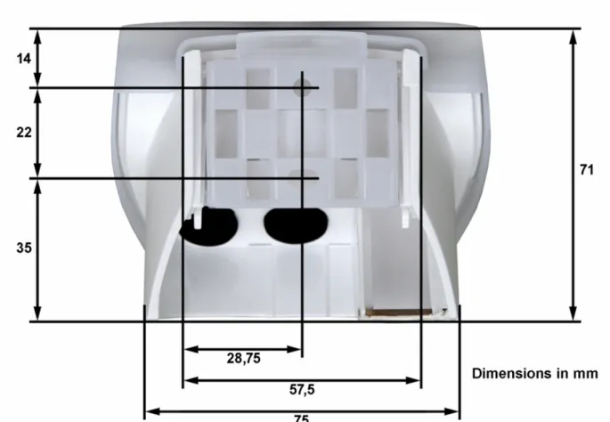
View of rear side and drill hole plan
Fig. 7 b: Dimensions of rear side of housing with bracket. Subject to change for technical enhancement.
The sensor cover snaps in on the left and right along the bottom edge (see Fig. 8). Remove the cover.
Push the connection cable through the rubber seal on the bottom of the weather station and push the power and bus cables onto their designated terminals. The connection is by typical telephone cable (J-Y(ST)Y 2 × 2 × 0.8).
Mounting the weather station
Close the housing by putting the cover back over the bottom part. The cover must snap in on the left and right with a definite “click”.
Fig. 9
Make sure the cover and bottom part are properly snapped together! This picture is looking at the closed sensor from underneath.
Fig. 10
Push the housing from above into the fastened mount. The bumps on the mount must snap into the rails in the housing.
To remove it, the sensor can be simply pulled upwards out of the mount, against the resistance of the fastening.
Notes on installation
Do not open the device if water (rain) could get in: even a few drops could damage the electronics inside.
Remove all existing protection labels after installation.
It will take 30 seconds after applying the power before the wind measurement will be output.
Maintenance
The device must be checked for dirt on a regular, twice-yearly basis and cleaned if necessary. A dirty sensor can lead to wind sensor failing to work.