© 2018, IRJET | Impact Factor value: 6.171 | ISO 9001:2008 Certified Journal | Page 2078
FRACTAL CPW-FED MULTIBAND ANTENNA
REKHA G
1, SHEFIN SHOUKATH
2, SHAMEER K MOHAMMED
31
M. Tech Student, Kerala Technical University, Muslim Association College of Engineering, TVM, Kerala, India
2Associate Professor, Dept. of ECE, Muslim Association College of Engineering, TVM, Kerala, India
3
Head of the Department, ECE, Muslim Association College of Engineering, TVM, Kerala, India.
---***---Abstract -The fractal coplanar wave guide fed multiband
antenna is designed. For designing this antenna FR4 epoxy substrate with thickness 1.6mm and relative permittivity of 4.4 is used as substrate. Five iterations to proposed antenna designed. And simulated by using High Frequency Structural Simulator V13 software. The different parameters of antenna such as return loss and Voltage standing wave ratio are analyzed. The obtained result shows the designed antenna works in multiple bands with suitable return loss and VSWR. The designed antenna can be used for different L,C and X band applications.Key Words: Fractal antenna, Coplanar wave guide, relative permittivity, return loss, VSWR, etc.
1. INTRODUCTION
Antenna is very important component in wireless communication system. It is a device which converts radio waves into electrical signal and vice versa. A Microstrip patch antenna consists of a radiating patch on one side and has a ground plane on the other side and has the attractive features of low profile, lightweight, easy fabrication, and conformability to mounting hosts [1]. The structural forms of the microstrip antennas are the rectangular and circular patch microstrip antenna. Operating frequency and size of the microstrip antenna are related to each other. That is for a large size antenna the operating frequency reduces and vice versa [2].Commonly the microstrip antenna having one or two frequency band and narrow band. Recently, in the world of wireless communication there is a need of multiple resonant frequencies and wide band antenna. So according to the need the latest research in antenna technology the fractal geometry of antenna took a vital role [3]. The need of multi band small size antenna is fulfilled by the design of fractal antenna [4].The concept of fractal was originally coined by French mathematician B.B. Mandelbrot [5]. The different shapes of fractal antenna has designed such as sierpinski carpet, sierpinski gasket and koch curve etc.[6]. Here square fractal rings are used to design the multi band antenna.
By the application of fractals to antenna elements following features can be achieved,
Smaller size
Multiband resonant frequencies.
Gain can be optimized
Wideband and multiband frequencies
1.1 Fractal Antenna
Fractal antenna is a multiband and wide band antenna, which repeats the base shape of antenna again and again. It means it is based on iterative method. Fractal geometry modifies the structure of conventional antenna, to improve the performance. The fractal antenna overcomes the problems of microstrip antenna like narrow band. Fractal geometry has two main properties such as self similarity and space filling, which are used to improve the performance. Self similarity means repeat itself after each iteration [7]. Also self similarity concept can achieve multiple frequency bands because at different scale different parts of antenna are similar to each other. In other words the fractal is a fragmented geometry shape which can be divided into parts, each of which is a reduced size copy of whole.
1.2 Coplanar wave guide
Coplanar wave guide (CPW) consists of a conductor strip at the middle and two ground planes are located on either sides of center conductor. All these lie in the same plane. Hence it is coplanar. The gap between the coplanar waveguide is usually very small [8].
1.3 L, S,Cand X bands
L band is the part of electromagnetic spectrum ranging from 1 to 2GHz.S band frequencies range from 2 to 4 GHz for weather radar, surface ship radar and some communication satellites. In C band the frequencies ranges from 4 to 8 GHz. It is also used for radar and satellite communications. The next band is X band it is ranging from 8 to 12 GHz for radar and satellite communications.
1.4 Iterative Function System
© 2018, IRJET | Impact Factor value: 6.171 | ISO 9001:2008 Certified Journal | Page 2079
2. ANTENNA DESIGN
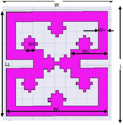
The design of proposed fractal antenna having a substrate of dimension51.9*51.9mm and height of 1.6mm. The substrate used is FR4 epoxy with thickness of 1.6mm and dielectric constant of 4.4. And fractal antenna designed having the same dimensions and coplanar wave guide is designed on the other side of the substrate.
Fig -1: Proposed fractal antenna
Fig -2: Coplanar wave guide
Fig-1 and 2 shows the design of proposed fractal antenna.
Five iterations are carried out to design the antenna as
illustrated in Fig-3. Generation of fractal antenna is an
iterative procedure. The fractals are applied to the square rings for reduction in whole antenna size. The antenna demonstrated in this paper is generated by increasing the number of fractals. In each iteration the number of fractals are increased. Also coplanar wave guide fed monopole is printed on the other side of substrate. The coplanar wave guide feeding is used to compact the antenna size and overcome the high impedance problem.
(a) (b)
(c)
(d) (e)
Fig -3: Step by step iteration of proposed fractal antenna
For designing this antenna, substrate used is FR4 epoxy. It is a popular and versatile high pressure thermoset plastic laminate grade with good strength to weight ratios. First iteration includes square rings of large dimensions. In the second iteration again small dimensions which divide the first square ring. In the third and fourth iteration, small sized fractals are applied to the square ring. The modified fifth iteration structure is obtained by applying dimension of small fractals to top and bottom sides of the square ring. Coplanar wave guide feeding is used for this fractal antenna design. For coplanar wave guide, wave port is designed with the width and height of the wave port as,
Width=3(2g+w) (1)
Height=4h (2)
where g is the gap between the coplanar conductor and monopole. And w is the width of the monopole and h is the height of the substrate. Depending on the parameters of these equations, port is designed for the coplanar waveguide.
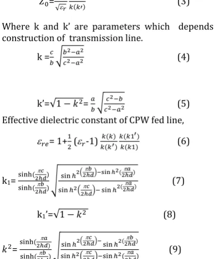
2.1 Design equations of coplanar wave guide feed line
[image:2.595.332.532.73.321.2] [image:2.595.52.257.185.393.2] [image:2.595.69.244.416.594.2] [image:2.595.361.508.634.735.2]© 2018, IRJET | Impact Factor value: 6.171 | ISO 9001:2008 Certified Journal | Page 2080 The microstrip patch antenna with finite ground plane
having substrate thickness equals to ‘hd’, has
characteristic impedance ‘Zo’ given by,
=
√
(3)
Where k and k’ are parameters which depends on the construction of transmission line.
k = √
(4)
k’=√ = √
(5)
Effective dielectric constant of CPW fed line,
= 1+ ( -1) (6)
k1=
√
( )
( ) (7)
k1’=√ (8)
=
√
( )
( ) (9)
[image:3.595.34.258.132.397.2]where k and k’ are parameters depends on the construction of coplanar waveguide transmission line having track width equals to ‘2a’, sum of the track width plus gaps on either sides equals ‘2b’ and total width (i.e. ground on either side plus ‘2b’) equals to ‘2c’ as shown in Fig-4. Here ‘K’ is the elliptical integral of first kind.
Table -1: Design parameters of proposed fractal antenna.
Parameters Label Dimensions
(mm)
Width of substrate W 51.9
Length of substrate L 51.9
Height of substrate h 1.6
Bottom ring length L1 46.9
Bottom ring width W1 46.9
Width of ring W4 4.5
CPW width W2 24
CPW length L2 24
CPW gap g 0.7
Width of monopole W3 2.5
Length of monopole L3 44.9
Length of fractal W5 12.63
Length of small fractal W6 5
Table-1 represents the required design parameters of the
proposed fractal antenna. The width and length of the substrate are 51.9mm.And the height of the substrate is 1.6mm. Bottom ring length and width of 46.9mm are used. And the fractals having dimensions of 12.63 and 5 is designed.
3.RESULT
3.1 Return Loss
Return loss is one of the important parameter of the antenna design characteristics. It is the loss of power in the signal reflected by a discontinuity in a transmission line. This discontinuity can be a mismatch with the terminating load or with a device inserted in the line. This term is related to both standing wave ratio and reflection coefficient. Increasing return loss corresponds to lower
SWR. Resonant frequency and operating band width can be
observed from this plot. Return loss plots of each iterations are shown in figures below.
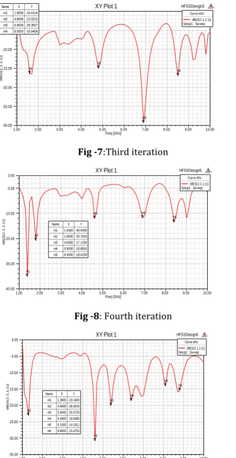
In the first iteration multiple bands with resonant frequencies 1.1GHz and 8.7 GHz can be obtained. By performing the second iteration three resonant frequencies 1.7GHZ ,6.6GHz and 8.8GHz with suitable return loss is achieved. The four resonant frequencies in the third iteration are 1.6GHz, 4.8GHz, 6.9GHz and 8.5GHz. In the fourth iteration the obtained resonant frequencies are 1.4GHz, 1.8GHz, 4.6GHz, 6.9GHz and 8.4 GHz. The final iteration attains six different resonant frequencies are sui 1.3GHz, 4.6GHz, 5.4GHz, 6.4GHz, 8.1GHz and 8.8GHz with a minimum return loss.
Fig -5: First iteration
Fig -6: Second iteration
1.00 2.00 3.00 4.00 5.00 6.00 7.00 8.00 9.00 10.00 Freq [GHz]
-17.50 -15.00 -12.50 -10.00 -7.50 -5.00 -2.50 0.00
d
B(S
(1
:1
,1
:1
))
HFSSDesign1
XY Plot 1 ANSOFT
m1
m2 Curve Info
dB(S(1:1,1:1)) Setup1 : Sw eep Name X Y
m1 1.1000 -16.3689 m2 8.7000 -15.6271
1.00 2.00 3.00 4.00 5.00 6.00 7.00 8.00 9.00 10.00 Freq [GHz]
-25.00 -20.00 -15.00 -10.00 -5.00 0.00
d
B(S
(1
:1
,1
:1
))
HFSSDesign2
XY Plot 1 ANSOFT
m1
m2
m3 Curve Info
dB(S(1:1,1:1)) Setup1 : Sw eep Name X Y
[image:3.595.49.551.474.794.2]© 2018, IRJET | Impact Factor value: 6.171 | ISO 9001:2008 Certified Journal | Page 2081
Fig -7:Third iteration
Fig -8: Fourth iteration
Fig -9: Proposed fractal antenna
In S11 plot frequency versus return loss is plotted (Fig-9).
The analysis of return loss plot of each iteration new band are obtained also the corresponding return loss reduces. The final iteration is better with having multiple bands and sufficient return loss. The proposed fractal antenna resonates at different frequency bands namely 1.3GHz, 4.6GHz,5.4GHz,6.4GHz, 8.1GHz and 8.8GHz with suitable return loss.
3.2 Voltage Standing Wave Ratio
[image:4.595.54.292.76.537.2]VSWR is the amount of mismatch between feed line and antenna. The smaller value of VSWR is better the antenna matched to the transmission line and more power delivered to the antenna. The VSWR plot of the proposed fractal antenna is shown in Fig-10.
Fig -10: VSWR plot of the fractal antenna
From this plot it is found VSWR is less than 2 it is suitable for better performance of antenna. The proposed antenna should possess a good performance in terms of return loss and VSWR.
4. CONCLUSION
The square fractal ring loaded coplanar wave guide fed antenna is designed. The antenna parameters such as return loss and VSWR are analyzed. The antenna will be able to operate well at multiple resonant frequencies with suitable performance. The proposed fractal antenna ensures multiband resonating frequencies with an acceptable value of return loss and VSWR. It makes it is suitable to operate for various communication band such as L, C and X band applications.
5. REFERENCES
[1]C. Y. Huang, J. Y. Wu, and K. L. Wong, “Slot-coupled microstrip antenna for broadband circular polarization,”
Electron. Lett.34, 835–836, April 30, 1998.
[2]Gurpreetkaur, Er.Sonia Goyal,” A Review Microstrip Patch Antenna Design,” ISOR Journal of Electronic and Communication Engineering (ISOR-JECE). Special Issue-AETMIS,1994.
[3]Satyadeep Das, Sudhakar Sahu “Square Fractal Ring Loaded CPW fed Circular Polarized Antenna” TENCON Procedings of the International Conference, 2016
[4]S. R. Chowdary, A. M. Prasad and P. M. Rao, “Design of Modified Sierpinski Antenna for WLAN Applications,”
International Conference on Electronics and
Communication System (ICECS), 2014.
[5]AmanpreetKaur,GursimranjitSingh,”A Review Paper on Fractal Antenna Engineering,” International Journal of Advance Research in Electrical, Electronic and Instrument Engineering and Computer Science. Volume- 3 Issue- 9 September, 2014 page no. 8270-8275.
[6]D. L. Jaggard, “On Fractal Electrodynamics,” in H. N. Kritikosand D. L. Jaggard (eds.), Recent Advances in
1.00 2.00 3.00 4.00 5.00 6.00 7.00 8.00 9.00 10.00 Freq [GHz] -30.00 -25.00 -20.00 -15.00 -10.00 -5.00 0.00 d B(S (1 :1 ,1 :1 )) m1 m2 m3 m4 Curve Info dB(S(1:1,1:1)) Setup1 : Sw eep m1 1.6000 -16.4104
m2 4.8000 -15.0215 m3 6.9000 -29.3557 m4 8.5000 -16.9406
1.00 2.00 3.00 4.00 5.00 6.00 7.00 8.00 9.00 10.00 Freq [GHz] -45.00 -35.00 -25.00 -15.00 -5.00 0.00 d B(S (1 :1 ,1 :1 )) HFSSDesign5
XY Plot 1 ANSOFT
m1 m2 m3 m4 m5 Curve Info dB(S(1:1,1:1)) Setup1 : Sw eep
Name X Y m1 1.4000 -40.0400 m2 1.8000 -25.7919 m3 4.6000 -17.1206 m4 6.9000 -16.8816 m5 8.4000 -18.6109
1.00 2.00 3.00 4.00 5.00 6.00 7.00 8.00 9.00 10.00 Freq [GHz] -35.00 -30.00 -25.00 -20.00 -15.00 -10.00 -5.00 0.00 d B(S (1 :1 ,1 :1 )) HFSSDesign6
XY Plot 1 ANSOFT
m1 m2 m3 m4 m5 m6 Curve Info dB(S(1:1,1:1)) Setup1 : Sw eep
Name X Y m1 1.3000 -23.1600 m2 4.6000 -30.8243 m3 5.4000 -20.0726 m4 6.4000 -18.6465 m5 8.1000 -14.1611 m6 8.8000 -15.4752
[image:4.595.322.543.79.210.2]© 2018, IRJET | Impact Factor value: 6.171 | ISO 9001:2008 Certified Journal | Page 2082 Electromagnetic Theory, New York, Springer-Verlag, 1990,
pp. 183-224.
[7]S. Yadav, P. Jain and R. Choudhary, “A Novel approach of triangular circular fractal antenna,” International Conference on Advances in Computing, Communications and Informatics (ICACCI), IEEE, pp. 708-711, 2014.
[8]Coplanar Microwave Integrated Circuits, by Ingo Wolff.Copyright© 2006 by VerlagsbuchhandlungDr.Wolff, GmbH. Published by John Wiley & Sons, Inc.