POWER SYSTEM LOADABILITY IMPROVEMENT BY
OPTIMAL ALLOCATION OF FACTS DEVICES USING
REAL CODED GENETIC ALGRORITHM
1R.MEDESWARAN, 2N.KAMARAJ 1,2
Department of Electrical and Electronics Engineering , Thiagarajar College of Engineeing, Madurai, Tamilnadu, India E-mail: 1 [email protected]
ABSTRACT
FACTS devices can effectively control the load flow distribution, improve the usage of existing system installations by increasing transmission capability, compensate reactive power, improve power quality, and improve stabilities of the power network. However, the location and settings of these devices in the system plays a significant role to achieve such benefits. This work presents the application of Real Coded Genetic Algorithm (RGA) for finding out the optimal locations, and the optimal parameter settings of single type and multi type FACTS devices to achieve maximum system loadability (MSL) in the power system. The FACTS devices used are Thyristor Controlled Series Capacitor (TCSC) and Unified Power Flow Controller (UPFC). The reactance model for TCSC and the decoupled model for UPFC are considered for this work. The thermal limits of the line and voltage limits of the buses are taken as constraints during the optimization. Simulated Binary Crossover (SBX) and Non-uniform polynomial mutation are employed to improve the performance of the Genetic Algorithm used. Simulations are performed on IEEE 6 bus and 30 bus power systems. The obtained results are encouraging and show the effectiveness of RGA.
Keywords: Loadability, FACTS, TCSC, UPFC, and Real Coded Genetic Algorithm
1. INTRODUCTION
Power flow over the transmission lines is mainly limited by some network characteristics such as thermal limits, stability limits, and voltage limits. Such limitations can be removed by adding new transmission and/or generation capacity. However, such solution is difficult for environmental, and economical reasons. Flexible Alternating Current Transmission Systems (FACTS), which is a concept proposed by N.G.Hingorani [1], are designed to remove such limitations. For a meshed network, optimal location of FACTS devices allows to control its power flows and thus to increase the system loadability.
Thyristor Controlled Series Capacitor (TCSC) is a device which offers smooth and flexible control for loadability enhancement with much faster response compared to the traditional control devices. Most of the researchers have focused on issues such as transient stability improvement, sub-synchronous resonance (SSR) mitigation, damping of power swings, avoiding voltage collapse, enhancing power system reliability, etc [2],[3].
The Unified Power Flow Controller (UPFC) is a versatile controller that can be used to control active and reactive power flows in a transmission line. UPFC is used to control the power flow in the transmission systems by controlling the impedance, voltage magnitude and phase angle. This
controller offers advantages in terms of static and dynamic operation of the power system[4],[5] .
2. PROBLEM FORMULATION 2.1 Objective function
Optimal location of FACTS devices to improve power system loadability has been mathematically formulated and is given by
(1)
J is the factor indicating violation of line flow limits and bus voltage limits and the objective is to maximize J.
NL Total number of lines NB Total number of buses
LFi Line flow Index objective function for line i
BFj Bus voltage violation objective function for bus j
(2)
(3)
LFi Line flow Index objective function for line i
BFj Bus voltage violation objective function for
bus j
BL Branch loading (Percentage of line flow respect to line capacity rate)
2.2 Device allocation and modeling
Multi type FACTS devices may have to be installed in order to achieve the desired performance. The solution for the optimal allocation problem includes the optimal location for the devices to be installed and the optimal settings of those installed devices so that the loadability is maximized.
[image:2.595.334.463.205.258.2]In this work, TCSC is modeled as a variable reactance. To avoid over compensation of the line, the reactance value variation is limited between -0.5 XL to + 0.5XL where XL is the reactance of the branch in which TCSC is connected.
Figure. 1. The Reactance Model Of TCSC
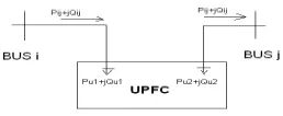
For UPFC, the decoupled model is used. This model is composed of two separate load buses since UPFC can control the power flow over the transmission line and bus voltages where it is installed.
Figure. 2. The decoupled model of UPFC
An UPFC has four variables Pu1, Qu1, Pu2, and Qu2. With the losses of the UPFC assumed to be neglected, the active power flow Pij that goes from bus i to bus j can be expressed by equation (4). An UPFC can control the power flow but cannot generate the real power flow. So the condition of equation (5) should be satisfied.
Pij = Pu1
(4)
Pu1+Pu2 = 0
(5)
Each reactive power output of the UPFC, Qu1 and Qu2 can be set to an arbitrary value within the capacity of UPFC to maintain the bus voltages. Therefore if multiple UPFCs are installed in the power system, the control variables of the k-th UPFC are represented as follows:
UPFC k-th = [Puk1 Quk1 Puk2 Quk2] (6)
Puk1 + Puk2 = 0 (7)
where, Puk1 - 1 st
bus active power of the k-th UPFC Quk1 - 1st bus reactive power of the k-th UPFC Puk2 - 2
nd
bus active power of the k-th UPFC Quk2 - 2
nd
bus reactive power of the k-th UPFC
2.3 Constraints
The following are the constraints associated with the formulated problem.
2.3.1 TCSC Constraint
0.5X L < X TCSC < 0.5X L (8)
XL- original line reactance in per unit XTCSC - reactance offered by TCSC
∏
∏
=
= ×
=
NB
j j
NL
i i
BF LF
J
2.3.2 UPFC Constraint
The constraints associated with the decoupled model of UPFC are as follows: -100 MW ≤ Pu1 ≤ 100 MW (9)
Pu2 = - Pu1
(10)
100 MVAR ≤ Qu1 ≤ 100 MVAR
(11)
-100 MVAR ≤ Qu2 ≤ 100 MVAR (12) where
Pu1, Pu2 are the real power injected into the system.
Qu1,Qu2 are the reactive power injected into the system.
2.3.3 Voltage Stability Constraints
The bus voltage Vb must lie within the following limits and VS represents the voltage violation.
(13)
2.3.4 Power balance Constraints
∑ PG = ∑ PD +PL
(14)
Pi = Σ Ei Ek [ Gik cos(θi-θk)+Bik sin(θi-θk)] (15)
Qi = Σ Ei Ek [ Gik sin(θi-θk)-Bik cos(θi-θk)] (16)
Where
θi ,θk - Phase angles at buses i and k
respectively.
Ei,,Ek - Voltage magnitudes at bus i and k respectively.
Gik,,Bik - Elements of YBus matrix. The bus voltage Vb must lie within the following limits and VS represents the voltage violation.
3. ALGORITHM
3.1 Real coded Genetic Algorithm
Genetic algorithm is a kind of stochastic search technique based on the mechanism of natural Selection and survival of the fittest [6],[7]. GA has its superior robust behaviour in nonlinear environments over the other optimization techniques. The architecture of
the GA implementation can be segregated into the following three constituent phases namely: initial population generation, fitness evaluation and genetic operations[10].
It has been widely confirmed that real-number encoding performs better than binary or gray encoding for constrained optimization. Owing to the adaptivecapability, SBX crossover and polynomial mutation operators are employed. Tournament selection is used as selection mechanism in order to avoid premature convergence
3.1.1 Simulated Binary Crossover
In SBX crossover [13], two offspring solutions are created from two parents as follows:
(
)
(
)
− ≤ = + + otherwise u u u c i i c i qi , 1 2 1 5 . 0 , 2 1 1 1 1 η η β (17) ( ) ( )(
)
( )(
)
( )[
]
( )
[
(
)
( )(
)
( t)]
i qi t i qi t i t i qi t i qi t i x x x x x x , 2 , 1 1 , 2 , 2 , 1 ) 1 , 1 ( 1 t 2, i 1 t 1, i 1 1 5 . 0 1 1 5 . 0 x and x offspring the compute Then β β β β + + − = − + + = + + + + (18)
3.1.2 Non-uniform Polynomial Mutation
Newly generated offspring undergoes polynomial mutation operation. The new offspring is determined as follows:
i L i U i t i t
i x x x
y − + + − +
= (1, 1) ( )δ
) 1 , 1 ( (19)
The parameter i
−
δ
is calculated from thepolynomial probability distribution.
m
m
p(δ)=0.5(η +1)(1−δ)η
(20)
( )
(
)
[
]
5 . 0 r if , r -1 2 -1 0.5 r if , 1 2 i 1 1 i i 1 1 ≥ < − = − + m m i i r η η δ(21)
ηm is the mutation index.
4. RESULTS AND DISCUSSION
The algorithm is implemented using MATLAB 7.10 on a PC with a Pentium IV processor and 1 GB RAM. To obtain the optimized output from the algorithm, ten trials with independent population initializations have been done.To achieve more effectiveness, the maximum number of function evaluations is set at 10,000.
4.1 Parameter Tuning for RGA
Population size =100
Crossover probability Pc=0.8
Mutation probability, Pm = 1/number of variables
Crossover index, ηc =5 Mutation index, η m =20.
4.2 Test Systems
Load increasing studies on the real power system are done for different aims in planning and operation process of the system. In this work, the algorithm is implemented in IEEE 6-bus and IEEE 30-bus test systems. The following three cases are considered for the analysis and the results are presented before and after placing the FACTS devices.
CASE 1: Increase of active power at any one load bus.
CASE 2: Increase of active power at any two load buses.
CASE 3: Increase of active power at all load buses
4.3 Ieee 6 Bus System
4.3.1 before placing the device
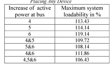
[image:4.595.314.500.140.250.2]The base loads are increased gradually and the power flow is performed for every increment of the load .The increment of the load continues until the line flow or bus voltage violation occurs. Table I shows the maximum system loadability that can be achieved for the base case system without any FACTS device.
Table 1: The Maximum System Loadability Before Placing Any Device
Increase of active power at bus
Maximum system loadability in %
4 113.43
5 114.14
6 119.14
4&5 109.72 5&6 108.14 4&6 111.86 4,5&6 106.43
4.3.2. after placing one upfc and one tcsc
CASE 1: Increase of active power at any one load bus.
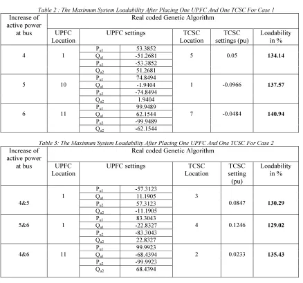
In this case, the real power demand is increased gradually in any one of the load buses. The proposed algorithms yield the suitable locations to install the UPFC and TCSC so that the maximum loadability is achieved. The settings of the devices and the percentage of loadability have been presented in Table 2. The load at bus 6 can be increased within thermal limits of the line and voltage limits of the buses, with the maximum loadability of 140.94% by installing one UPFC and one TCSC in 11th and 7th location respectively, with the recommended settings given by RGA.
CASE 2: Increase of active power at any two load buses.
In this case, the real power demand is increased gradually in any two load buses. The optimum locations and settings for the FACTS devices to be installed, and the percentage of maximum loadability that can be achieved have been presented in Table 3. The load at bus 4 and 5 can be increased within thermal limits of the line and voltage limits of the buses, with the maximum loadability of 135.43% by installing one UPFC and one TCSC in 11th and 2nd locations respectively, with the recommended settings given by RGA .
CASE 3: Increase of active power at all load buses.
settings by RGA , the maximum loadability of 124.43% can be achieved. Figure.3 illustrates
the comparison of maximum system
[image:5.595.72.510.187.597.2]loadability of IEEE 6 bus system for different cases.
Table 2 : The Maximum System Loadability After Placing One UPFC And One TCSC For Case 1
Increase of active power
at bus
Real coded Genetic Algorithm
UPFC Location
UPFC settings TCSC
Location
TCSC settings (pu)
Loadability in %
4 1
Pu1 53.3852
5 0.05 134.14
Qu1 -51.2681
Pu2 -53.3852
Qu2 51.2681
5 10
Pu1 74.8494
1 -0.0966 137.57 Qu1 -1.9404
Pu2 -74.8494
Qu2 1.9404
6 11
Pu1 99.9489
7 -0.0484 140.94 Qu1 62.1544
Pu2 -99.9489
Qu2 -62.1544
Table 3: The Maximum System Loadability After Placing One UPFC And One TCSC For Case 2
Increase of active power
at bus
Real coded Genetic Algorithm
UPFC Location
UPFC settings TCSC
Location
TCSC setting (pu)
Loadability in %
4&5
1
Pu1 -57.3123
3
0.0847 130.29 Qu1 11.1905
Pu2 57.3123
Qu2 -11.1905
5&6 1
Pu1 83.3043
4
0.1246 129.02 Qu1 -22.8327
Pu2 -83.3043
Qu2 22.8327
4&6 11
Pu1 99.9923
2 0.0233 135.43 Qu1 -68.4394
Pu2 -99.9923
Qu2 68.4394
Table 4: The Maximum System Loadability After Placing One UPFC And One TCSC For Case 3
Increase of active power
at bus
Real coded Genetic Algorithm
UPFC Location
UPFC settings TCSC
Location
TCSC setting (pu)
Loadability in %
4, 5 &6 1
Pu1 -89.8982
7 0.0999 124.43 Qu1 -46.9166
Pu2 89.8982
4.4 IEEE 30 Bus System
The IEEE 30-bus system consists of 1 slack bus, 5 generator buses, 24 load buses and it consists of 43 branches. To simulate this case, active load is increased at bus 4, bus 5 and bus 6 simultaneously. Table 5
shows the locations and settings of UPFC and TCSC to achieve the maximum loadability for case 3. By placing the devices in proposed locations with the recommended settings by RGA, the maximum loadability of 136.72%
[image:6.595.72.321.235.531.2]can be achieved.
Table 5: The Maximum System Loadability After Placing One UPFC And One TCSC For Case 3
Increase of active power
at bus
Real coded Genetic Algorithm
UPFC Location
UPFC settings TCSC
Location
TCSC settings
(pu)
Loadability in %
4, 5 &6 2
Pu1 -88.32
40 0.0189 136.72 Qu1 11.52
Pu2 88.32
Qu2 -11.52
Figure.3 Comparision Of Maximum System Loadability (MSL) For IEEE 6 Bus System
5.CONCLUSION
This work presents the application of Real coded Genetic Algorithm for finding out the optimal locations and the optimal settings of Multi-type FACTS devices ,TCSC and UPFC, to achieve maximum system loadability in the power system. The thermal limits of the lines and the voltage limits of the buses are taken as constraints during the optimization. Simulated Binary Crossover and Non-uniform Polynomial mutation have been adopted for enhancing the performance of RGA. Simulations have been performed on IEEE 6-bus and IEEE 30-bus power systems for three different cases. The difference cases are considered in this work to perform loadability. The results show the
effective control of the load flow distribution to improve the usage of existing system installations by increasing transmission capability. The comparison of results shows the effectiveness of the proposed algorithm in terms of enhanced loadability.
REFRENCES:
[1] N. G. Hingorani, “Power electronics in electrical utilities: role of power electronics infuture power systems”, Proceedings of the IEEE,Vol. 76 No. 4, April 1988, pp.481-482.
[2] M. Saravanan et al, “Application Of PSO Technique For Optimal Location Of FACTS Devices Considering System Loadability And Cost Of Installation”, Electric Power system research , July 2007.
[3] Y. Xiao, Y. H. Song, C. C. Liu, and Y.Z.Sun, “Available transfer capability enhancement using FACTS devices”, IEEE Transactions on Power Systems, vol. 18, no. 1, February 2003.
[4] Abdel salam and aly , “Optimal location of UPFC in electrical Power systems”, IEEE conference proceeding, 2004.
[5] S. Gerbex, R.Cherkaoui, and A.J.Germond, “Optimal location of multi-type FACTS devices by means of genetic algorithms”,
IEEE Transaction on Power-Systems, vol. 16, pp.537-544, 2001.
[6] Goldberg, D. E., Genetic Algorithms in Search Optimization and Machine Learning,
[7] Coley, D. A., “An Introduction to genetic Algorithms for Scientists and Engineers”,
World Scientific Publishing Co, 1999.
[8] A. Shandilya, H. Gupta, and J. Sharma, “Method for generation rescheduling and local shedding to alleviate line overloads using local optimization”,Proc. Inst. Elect. Eng., Vol. 140, pp. 337–342, Sept.1993
[9] Ahad Kazemi, Mahmoud Vakili
Sohrforouzani, “Power system damping using fuzzy controlled FACTS devices”, Electr. Power and Energy Systems. Vol.28, pp.349-357, 2006.
[10]G. Stephane, C. Rachid and J. G. Alain, “Optimal location of multi-type FACTS devices in a power system by means of genetic algorithms” , IEEE Trans. Power systems, Vol. 16, No.3, pp. 537-544, August 2001.
[11] D. Radu, and Y. Besanger, “A multi-objective genetic algorithm approach to optimal allocation of multi-type FACTS devices for power system security”, IEEE Power Engineering Society General Meeting, 18-22 June 2006.
[12] S.Krishna,K.R.Padiyar, “Discrete control of unified power flow controller for stability improvement”, Electrical Power Systems. Research, vol.75, pp178-189, 2005.
[13] Sunith Bandaru, Rupesh Tulshyan , kalyanmoy Deb , “Modified SBX and Adaptive Mutation for Real World Single Objective Optimization” IEEE Transactions on Evolutionary Computation , 2011 , pp. 1335 -1342 2011