TUMBLING TOTAL HARMONIC DISTORTION IN MULTI
INVERTER WITH THE AID OF HYBRID (GA-PSO)
1V.S.BHARATH, 2M.GOPINATH
1Research Scholar, Bharath University, Chennai.
2Professor/EEE,Dr.N.G.P Institute of Technology, Coimbatore
E-mail: [email protected]
ABSTRACT
Multi level inverter is a device used for converting DC voltage to AC voltage. Multilevel inverters are a source of high power, often used in industrial applications and can use either sine or modified sine waves. Generally IGBT switches are used in the inverter to control this switching operation. Instead of using one converter to convert an AC current into a DC current, a multilevel inverter uses a series of semiconductor power converters (usually two to three) thus generating higher voltage. At the output of the multilevel inverter the sine wave form produces large harmonics. To reduce these harmonics at the output signal, the corresponding THD of switching angles must be reduced. Generally genetic algorithm is used for harmonic optimization. But the drawback is the cost function becomes more difficult to optimize and requires increased number of iterations. Hence to reduce the number of iteration we proposed a hybrid of Genetic algorithm and Particle swarm optimization algorithm to optimize the switching angles. Hence the corresponding THD value is also reduced. The proposed technique is implemented in the MATLAB/simulink working platform.
Keyword: Total Harmonics Distortion (THD), Genetic Algorithm (GA), Particle Swarm Optimization
(PSO)
1. INTRODUCTION
It has been an amazing aspect of the last decade that multilevel inverters have riveted keen attention with their paramount and potential applications in power techniques and industrial drives. [1]They are capable of being effectively applied in the disseminated power techniques where output ac voltage is derived by linking dc sources like batteries, fuel cells, solar cells, rectified wind turbines etc at input segment of the inverters. [2]The ac output voltage derived from the inverters can be nourished to a load straight or interconnected to the ac grid devoid of voltage harmonizing issues. [3] Moreover, the multilevel inverters are employed as voltage source inverters (VSIs) in the static synchronous compensator (STATCOM), a reactive power balancing method made use of for controlling voltage in power technologies [4]
The multilevel inverters glisten with various glittering qualities in relation to the hard-switched two-level pulse width modulation inverters, evidenced by their competency to perform at lofty voltage with lesser dv/dt per switching, elevated efficiency, little electromagnetic hindrance etc [5]
High-pitched magnitude sinusoidal voltage with enormously little deformation at basic frequency can be formed at output using multilevel inverters by linking adequate number of dc levels at input side. [6] There are principally three kinds of multilevel inverters such as a) diode- clamped, b) flying capacitor and c) cascade multilevel inverter (CMLI). Of the three, CMLI possesses a modular configuration and needs only little number of components when compared to the other two topologies, and consequently, it is extensively employed for numerous applications in electrical engineering [7]
To create multilevel output ac voltage by means
of various intensities of dc inputs, the
selective harmonic elimination (SHE) equations. [9] As the SHE equations are non linear transcendental in character, their solutions can be either a simple root or compound root and even no root at all for a specific value of modulation index (m). Moreover, it is very hard to find a solution to these equations. The major issue focuses on how to derive the entire likely solution sets where available employing easy and less mathematically intricate procedures. After arriving at these solution sets, the switching angles yielding least total harmonic deformation (THD) in the output ac voltage are chosen for switching of the power electronics systems. [10]
In [11]-[12], iterative statistical methods have been executed to find solutions to the SHE equations having only one solution set, where a suitable initial conjecture and initial value of m for which the solutions subsist are essential. As a rule, it is hard to estimate the preliminary solution and the value of m for which solution is available
In [13], theory of resultants of polynomials and the theory of symmetric polynomials has been recommended to find roots of the polynomial
equations derived from the transcendental
equations. A snag wih these methods is, for several H-bridges linked in succession, the order of the polynomials tends to be too high, resulting in the calculations of roots of these polynomials highly intricate. In addition, these methods have been made functional up to 11-level multilevel inverters only because of the complication in calculation related to these methods. [14]
2. RELATED WORKS
In 2013, Gobinath.K et al. [15] have propounded the method for finetuning the proficiency of the multilevel inverter and excellence of output voltage waveform. Seven level abridged switches topology had been run with only seven switches. Fundamental Switching scheme and Selective Harmonics Elimination were executed with a view to decrease the Total Harmonics Distortion (THD) value. Selective Harmonics Elimination Stepped Waveform (SHESW) method was put into practice to ward off the lower order harmonics. Basic switching scheme was used to check the power electronics switches in the inverter. The topology was appropriate for any number of levels. The harmonic decrease was attained by choosing fitting switching angles. It portends hope to decrease preliminary overhead and intricacy, hence being suitable for industrial applications. In the paper third and fifth level harmonics have been wiped off.
In 2009, Mehrdad Tarafdar Hagh et al. [16] have detailed a solution to the harmonic minimization dilemma making use of an innovative particle swarm optimization (PSO) method based on species-based PSO (SPSO). The initial SPSO was altered, which enhanced the strength of algorithm to locate global optimum of the search space. The technique could spot the optimum switching angles when their number was enhanced, which was not within the reach of the traditional iterative methods or resultant theory technique. Academic outcomes were tested by investigations and replicationsfor an 11-level H-bridge inverter. Outcomes prove that the new technique efficiently reduces a huge number of exact harmonics, and the output voltage results in very low total harmonic deformation and switching frequency.
In 2009, R.N. Ray et al. [17] have introduced switching angles for selected harmonic elimination (SHE) in a multilevel inverter employing the particle swarm optimization method. For a chosen fundamental voltage, the switching angles were determined by the designed algorithm while removing the lower-order harmonics. Also, the chosen higher-order harmonics are removed by supplementary switching to put in least total harmonic distortion (THD) for the output voltage. The switching angles calculated for most favorable THD at changing modulation index were saved as a look-up table in digital signal processor (DSP) memory for online application, thereby decreasing the online calculation load of resolving the non-linear equations of SHE problem. Direct solution of non-linear transcendental equations of SHE problem could pave the way for discontinuity at definite modulation indices. Here the switching angles were calculated offline taking into effect most favorable voltage THD whereas chosen harmonics are removed at all likely modulation
indices including the point of discontinuity.
In 2012, M.Murugesan et al. [18] have suggested a new technique which dwindled the number of
restricted switches utilized in conventional
multilevel inverter. To set up a single phase system, the multilevel inverter needed one H-bridge and a multi conversion cell. A multi conversion cell consists of three equal voltage sources with three restricted switches and three diodes. In traditional
technique, twelve controlled switches were
radically decreased the intricacy of control circuit, cost, and lower order harmonics and thus successfully dwindles total harmonic deformation.
In 2012, Carlos Alberto Lozano Espinosa et al. [19] have given birth to an epoch-making algorithm to determine the switching angles of a cascaded multilevel inverter reducing the total harmonic deformation. The execution was used a cascaded multilevel inverter with only one battery feeding one bridge and one transformer for each switching angle and linked in cascade with the supplementary transformers. A contrast of total harmonic distortion (THD) with choosy harmonic exclusion method and the angles computation with the algorithm were exhibited.
3. MULTI LEVEL INVERTER
The concept of multilevel converters has been introduced since 1975. The term multilevel began
with the three-level converter.An inverter used for
conversion of DC power to AC power, usually at a controlled frequency and voltage. These work by
controlling a switching device like an IGBT. An
IGBT inverter uses four IGBT switches in an "H-bridge" configuration to convert a DC voltage to a square wave ac voltage for driving motors. Nowadays, there exist three commercial topologies of multilevel voltage-source inverters: neutral point clamped (NPC), cascaded H-bridge (CHB), and flying capacitors (FCs). Among these inverter topologies, cascaded multilevel inverter reaches the higher output voltage and power levels (13.8 kV, 30 MVA) and the higher reliability due to its modular topology. The cascaded H-bride multi level inverter is to use capacitors and switches. One of the advantages of this type of multi level inverter is that it needs less number of components compared with diode clamped and flying capacitor inverters.
Figure1: Multi Level Inverter
The multilevel inverter has better working performance compared to the conventional Pulse Width Modulation (PWM) inverters. It provides
even voltage sharing, both statically and
dynamically; reduce the size and volume due to the elimination of the bulky coupling transformers or
Harmonics in multi level inverter
Output voltage of multi level inverter is expressed in Fourier series as:
) cos sin ( ) ( 1 n
n Sn nβn Tn nβ x
V
∑
∞= +
= (1)
Where,
V(x) - output voltage of multi level
inverter
Sn - odd harmonics
Tn - even harmonics
βn - switching angle of nth harmonic
At output voltage the even harmonics are absent because of the falling edge of the staircase
waveform (ie, Tn= 0). Hence only the odd-order
harmonics are present at the output voltage. Sn can
be expressed with only first quadrant switching angles β1, β2….βm.
∑
== m
i i
dc
n V nπ nβ
S
1(cos( ))
) / 4
( (2)
also,
0 < β1 < β2<……. Βm < (π/2)
where m is the number of variables corresponding
to switching angles β1 through βm of the first
quadrant.
In selected harmonic elimination (SHE) Sn is
assumed as the desired value for the fundamental component and its value is equated to zero.
∑
= == m
i i
dc π β L
V S
1
1 (4 / ) (cos( ))
∑
= == m
i i
dc π β
V S
1
3 (4 /3 ) (cos(3 )) 0
∑
= == m
i i
dc
n V nπ nβ
S
1(cos( )) 0
) / 4
(
Here L is the fundamental components amplitude.
Non-linear transcendental equations are formed
and after solving these equations, a1 through ak are
computed. Triplen harmonics ie, unbalanced harmonics are eliminated in a three-phase balanced system and these are not considered in above equation.
Total harmonic distortion
Total Harmonic Distortion (THD) is an amplifier or pre-amplifier, which compares the amplifiers output signal with the input signal. This comparison measures the harmonic frequencies of the two signals to find the level difference. This difference is called total harmonic distortion. Generally THD is measured in terms of percentage (for example: 0.005% THD). THD with lower percentage are the better result. THD with lower percentage allows the components in the loud speaker; amplifier or other equipment produces accurate output by reduction of harmonics which are added by electronics and other medium. THD with <1% is inaudible to human ear and highly fidelity.
Total harmonic distortion can be calculated using the given formula
[ ]
100 5 2 2 1 Χ =∑
∞ = n n S S i THD where , ...) 3 , 2 , 1 ( 16 ± =
= i i n
Flow chart explanation
Initially by considering the number of population and number of generation switching angles are generated. Next index generation is done by calculation the modulation index. Modulation index indicates how much the carrier's amplitude can change due to modulation. When dealing with multiple harmonics, the modulation result will be a signal with multiple harmonics as well. Therefore
any calculations must be done separately for each input harmonic.
Each harmonic should be treated has a single input signal and in the end the several output signals should be summed. Modulation index does not account for input signal's amplitude directly. Using these population indexes is found which
and find the objective function F(β). In general Sn is assigned as the desired value for the fundamental component. The values of switching angles must be between 0 and 90. If the switching angles do not exist between these values then our proposed method is adopted.
Generation of chromosome
Initially random solution is generated using the switching angle. Generally switching angles are taken from the output of the multi level inverter. Each single group of switching angle is set as single chromosome. Thus initial population is generated.
Calculation of fitness
Fitness value is evaluated from this set of
chromosome. Select the chromosome with
minimum fitness value as the solution of current generation. If the current generation is greater than the minimum generation then find new population by genetic operator; or else stop the process. The chromosome with minimum fitness value is set as optimal solution for the next stage.
Crossover
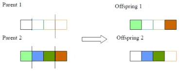
[image:6.612.100.285.466.545.2]After the parents have been selected by the selection method, crossover takes place. Crossover is an operator that mates the two parents (chromosomes) to produce two offsprings. The two newborn chromosomes may be better than their parents and the evolution process may continue. The crossover in carried out according to the crossover probability.
Figure 2: two point cross over
Velocity computation
Mutation is the function of the generating new offspring from the single parent and maintained the diversity of the each chromosome. In our proposed method we are using velocity computation instead of mutation.PSO is initialized by a group of random particles. It also searches for optima by updating generations. In Each Iteration, the values are updated using the two values such as pbest and lbest. The first value is the best value it has ever achieved and it is stored in the memory. It was named as pbest. Another best value tracked by the particle swarm optimizer, the location is called the gbest. When a particle takes part of the population
as its topological neighbors, the best value is a local best and is called lbest.
[ ] [ ]V G rd( ) (pbest[ ] pre[ ]) G rd( ) (gbest[ ] pre[ ])
V = + 1* * − + 2* * −
[ ]
pre[ ] [ ]
Vpre = +
Where
V[ ] = particle velocity Pre [ ] = current particle
rd ( ) = random number between (0, 1) G1,G2 = learning factors
Usually G1 = G2 = 2
Final solution
Generally the output of the velocity computation gives the optimized switching angles. If the optimal solution is not produced then the process is iterated till the desired optimal solution is obtained. The
value of the switching angles lies between 0 to 90o
.These optimized switching angles give the corresponding THD value. Depending on the switching angles their corresponding THD of the output voltage gets reduced. Thus we get optimized switching angle as the output for this process.
4. RESULT AND DISCUSSION
This section discussed the experimental results of our proposed method for optimized THD value using hybrid GA and PSO technique.
Our proposed method highlights on the reduction of the THD value by optimizing the switching angle value. The table given below shows the output of the method which calculates the THD
value without any optimization method,
optimization method done by GA, PSO, and the hybrid of both GA and PSO. The experiment was done with three different switching angles and the corresponding THD value is calculated. It clearly explains that our proposed method
Table No 1: Switching Angles Based THD Values
Process β1 β2 β3 THD
Normal
output 25.83 69.675 96.3 44.3768
GA 17.8709 32.9047 81.3065 10.0876
PSO 5.2218 49.0919 76.0699 6.7112
Hybrid 0.3283 31.2717 68.3999 2.1962
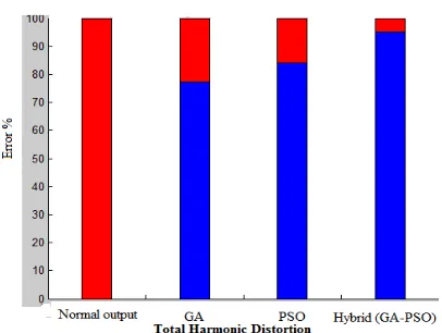
Figure 3: Bar Graph Showing That Our Proposed Method Provide Reduced THD Value
The above figure mentions the relation of the THD value for different set of experiment. In considering the output without any normalization method we get an output with 44.37% reduction in harmonics. Next while focusing on the GA process we get normalization of 77.27% reduction in output harmonics compared with the normal output. While comparing the normal output with PSO we get 84.88% of normalized THD value. But in our proposed method we can optimize THD value upto 95.05% with comparing to the normal output and proves that our proposed method is highly effective.
Figure 4: Graph Showing Relation Between Iteration And Corresponding Iteration
The graph represents the relation between iteration and the corresponding THD value. Initially considering the GA technique which shows that the THD value varies till the 18th iteration; after 18th iteration it remains a constant value of 10.0876. On considering PSO technique; THD value varies steeply at first and decreases gradually till an
approximation of 72th iteration and remains
constant. While focusing on our hybrid method the
THD value varies till an approximate of 68th
iteration and after that remains constant with the THD value of 2.1962.thus from the iteration graph it is clear that the proposed method produces lowest
THD value at an approximation of 68th
5. CONCLUSION
In this paper we have discussed about the hybridization of Genetic algorithm and Particle swarm optimization method for the harmonic elimination in multilevel inverter and it is simulated in the MATLAB platform the switching angles are calculated for the normal output, GA based output , PSO based output and th corresponding THD values are also calculated. The proposed method performances were compared to the multilevel inverter output voltage done by two separate algorithms. The simulation result reveals that the proposed hybrid GA +PSO gives better THD value. The comparison result shows that the proposed method is the well enhanced technique to eliminate the harmonics, which is competent over the other techniques.
REFERENCE
[1] Bindeshwar Singh, Nupur Mittal Dr. K.S. Verma, Dr. Deependra Singh, S.P. Singh, Rahul
Dixit, Manvendra Singh And Aanchal
Baranwal, “Multi-Level Inverter: A Literature Survey On Topologies And Control Strategies”, International Journal of Reviews in Computing, Vol. 10, No. 1, pp. 1-16, 2012
[2] Burak Ozpineci Leon M. Tolbert and John N.
Chiasson, “Harmonic Optimization of
Multilevel Converters Using Genetic
Algorithms”, in proceedings of IEEE Power Electronics Specialisu Conference, pp. 3911-3916, Aachen. Germany, 2004
[3] Anup Kumar Panda and Yellasiri Suresh, “Research on cascade multilevel inverter with single DC source by using three-phase transformers”, Electrical Power and Energy Systems, Vol. 40, pp. 9–20, 2012
Voltage Source Inverter Subjected to a New
Pulse Width Modulation Scheme”, The
Institution of Engineers, Vol. 72, No.3, pp. 46-55, September 2009
[5] Venkatachalam Kumar Chinnaiyan, Jovitha Jerome and J. Karpagam, “An experimental investigation on a multilevel inverter for solar energy applications”, Electrical Power and Energy Systems, Vol. 47, pp. 157–167, 2013
[6] Ebrahim Babaeia, Mohammad Farhadi
Kangarlua, Mehran Sabahia, Mohammad Reza Alizadeh Pahlavani, “Cascaded multilevel inverter using sub-multilevel cells”, Electric Power Systems Research, Vol. 96, pp. 101– 110, 2013
[7] D. Schutz and M. Ropp, “Simulation and
Experimental Study of Multi-Inverter
Islanding”, IEEE Transactions, pp. 1-4, 2011 [8] Dr. Jagdish Kumar, “THD analysis for different
levels of cascade multilevel inverters for industrial applications”, International Journal of Emerging Technology and Advanced Engineering, Vol. 2, No. 10, pp. 237-244, October 2012
[9] Amit Kumar Gupta and Ashwin M.
Khambadkone, “A General Space Vector PWM Algorithm for Multilevel Inverters Including Operation in Over modulation Range”, IEEE Transactions on Power Electronics, Vol. 22, No. 2, pp. 517-526, March 2007
[10] S. Thamizharasan, Baskaran, S. Ramkumar and S. Jeevananthan, “A new dual bridge multilevel dc-link inverter topology”, Electrical Power and Energy Systems, Vol. 45, pp. 376–383, 2013
[11] L. M. Tolbert, F. Z. Peng, and T.G. Habetler, “Multilevel converters for large electric drives”, IEEE Transactions on Industry Applications, vol. 35, no. 1, pp. 36-44, Jan. /Feb. 1999. [12] F. Z. Peng, J. W. McKeever, and D. J. Adams,
“Cascade Multilevel Inverters for Utility Applications”, IECON Proceedings (Industrial Electronics Conference), vol. 2, pp. 437-442, 1997
[13] John N. Chiasson, Leon M. Tolbert, Keith J. McKenzie, Zhong Du, “Control of a Multilevel Converter Using Resultant Theory”, IEEE Transactions on Control Systems Technology, vol. 11, no. 3, pp. 345-353, May 2003
[14] Ebrahim Babaei and Mohammad Sadegh Moeinian, “Asymmetric cascaded multilevel inverter with charge balance control of a low
resolution symmetric subsystem”, Energy
Conversion and Management, Vol. 51, pp. 2272–2278, 2010
[15] Gobinath.K, Mahendran.S and Gnanambal.I, “New Cascaded H-Bridge Multilevel Inverter
with Improved Efficiency”, International
Journal of Advanced Research in Electrical, Electronics and Instrumentation Engineering, Vol. 2, No. 4, pp. 1263-1271, April 2013 [16] Mehrdad Tarafdar Hagh, Hassan Taghizadeh
and and Kaveh Razi, “Harmonic Minimization in Multilevel Inverters Using Modified Species-Based Particle Swarm Optimization”, IEEE Transactions on Power Electronics, Vol. 24, No. 10, pp. 2259-2267, October 2009
[17] R.N. Ray, D. Chatterjee and S.K. Goswami, “Harmonics elimination in a multilevel inverter
using the particle swarm optimisation
technique”, IET Power Electron., Vol. 2, No. 6, pp. 646–652, 2009
[18] M.Murugesan, R.Sakthivel, E. Muthukumaran and R.Sivakumar, “Sinusoidal PWM Based
Modified Cascaded Multilevel Inverter”,
nternational Journal Of Computational Engineering Research, Vol. 2, No. 2, pp. 529-539, 2012
[19] Carlos Alberto Lozano Espinosa, Ivonne
Portocarrero, and Mauricio Izquierdo,