Simulink Model Analysis of Modulation Technique of UWB, OFDM and
CDMA for Different Parameter
Pooja Budhwar
1Rajeev Kumar
2Dheeraj Kapoor
3Pankaj Gupta
4Nipin Gupta
51
Student
2,3Assistant Professor
4,5Assistant Professor
1,2,3,4,5
Department of Electronics and Communication Engineering
1,3,4,5
Vaish College of Engineering, MDU Rohtak, India
2PIET Kurukshetra, India
Abstract— With pace of time there is tremendous
development in communication and on other hand as population increasing exponentially with time many severe traffic situations arises for example congestion problem, quality of service and cost also. A researcher always tries to resolve complexity of the system means system must be simple, cost effective and easy to use. In our dissertation research area is to compare different characteristics parameters of digital modulation technique so that a final conclusion can be made which technique is best one when we transmit data and finally it reach at destination with minimum bit error rate (BER). In base paper only CDMA technique is considered but in our dissertation work UWB and OFDM also considered. In our research paper we implemented simulation result CDMA, OFDM and UWB for different band pass technique for example BPSK, QPSK, QAM, 16 QAM, 64QAM, Calculate Transmitter and receiver message of CDMA, OFDM and UWB, Bit Error Rate, Signal-to-Noise ratio (SNR) and MSE Equalizer. Besides this our dissertation having multi input multi output (MIMO) antenna concept used. Earlier single antenna concept was used, now we use array of antenna to provide much efficient and good quality of service or we can say MIMO (Multi input Multi Output). Key words: Digital Modulation, UWB, QAM, OFDM, AWGN, Bit Error Rate, Signal to Noise Ratio
I. INTRODUCTION
CDMA (code division multiple access), OFDM (orthogonal frequency division multiplexing) and UWB (ultra-wide band) system which Simulink with communication and DSP signal library with smart antennas for multiple transmits and receives system. Most 3G mobile communication systems running on Code Division Multiple access as their digital modulation technique. As to the latest scenario, ultra-wide band system existence is impulse radio, in which ultra-short baseband pulses are utilized with a different modulation schemes for transferring data. As compared to OFDM impulse radio it consists significant advantages, as it can penetrate through material easily and besides this multipath path length differences can be resolved on the order of a foot or less [6]
II. LITERATURE REVIEW
CDMA, OFDM and UWB are the most developing technologies in modern mobile communication [1]. OFDM is fast transmission technique, means it utilize parallel pipelining concept [2, 5]. In this technique high data rate which is serial break into set which have low data rate which is known as sub streams, each of which is modulated on a separate subcarrier. In the year around 1980 there are scarcities of resources through which data can be transferred through atmosphere using concept of electromagnetic waves.
Few technologies are listed which are used during earlier like aloha (Aloha is of two type slotted and pure aloha and throughput of both techniques are different and slotted is superior to pure aloha), packet radio, carrier sense technology [1]. As per time new technologies came into market which are simpler, cost effective and having high efficiency. Firstly techniques are analog and after that they are replaced by digital technique. Thereafter a tremendous research carried out by scientists and more advance technology came into existent. UWB system suitable for indoor wireless environment and due to this a problem arises that channel suffers from frequency-selective fading [7-8]. OFDM system is simpler with respect to DS-CDMA, but it cannot solve the difficulty of power. RAKE receiver is not utilized by MC-CDMA due to its simplicity with respect to DS-MC-CDMA and when there is comparison regarding efficiency it is superior to Orthogonal Frequency Division Multiplexing at low power of signal [4, 13]. BER performance analysed with help of computer simulation in downlink channel. The proposed techniques break up Ultra-Wide Band channels into smaller channels which are in parallel. Ultra-Wide Band signals are having more information so they are also known as multipath rich signal. If concept of iterative turbo decoding used then efficiency of the receiver definitely increase. Dissertation revolves around analysis of various parameters like SNR, MSE and BER of UWB receivers and then compare with other techniques. In receiver section RAKE receiver used for good reception of signal and in it RAKE filtering also used so that maximum multipath diversity achieved and which enhance performance of the system. Cognitive Radio plays a very crucial role in our cross-layer ultra-wide band receiver architecture where it send and receive information with the physical layer for probable channel conditions before allocating links dynamically for its data transmission.
III. METHODOLOGY
Smart antenna also known as MIMO and to design this one is backbone of our dissertation. Array of antenna is used to enhance many performances and if antennas order be increase then complexity increases so much so we have to maintain tradeoff between cost and complexity. Smart antenna plays very important part in our dissertation work so that transmitted signal could be detected efficiently
A. Code Division Multiple Access
Fig. 1: Transmitter Block Diagram of CDMA The received signal is first filtered and then digitally converted with a sampling rate. It is followed by a rake receiver. After the correlation process executed, then all detected paths power is summed and at lastly, de-mapping procedure and Forward error check decoding are executed for data integrity.
Fig. 2: Receiver Block Diagram of CDMA
B. Orthogonal Frequency Division Multiplexing
Fig. 3: OFDM Transceiver Model
OFDM is preferably used for the uplink in a multiuser environment; low-order modulation such as QPSK with Gray mapping is preferred [10]. Now when we split sub- carrier it can be of two types which are of fixed and dynamic in nature. When system robustness considered in that case dynamic assignment of sub-carriers preferable and due to it system performance also increases.
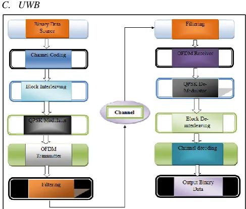
C. UWB
Fig. 4: UWB Transceiver Model
IV. RESULT AND DISCUSSION
A. CDMA Block Diagram
[image:2.595.47.296.298.684.2]CDMA performance of different parameters carried out in MATLAB 2013a simulation platform. In our dissertation work base paper consisting CDMA part only so first of all CDMA part executed and besides this OFDM and UWB through technique multipath fading and AWGN transmission channel. The simulation results of CDMA are shown here:
Fig. 5: CDMA System using QAM 256 modulation
Fig. 6: Transmitted & Received Signal of CDMA using QAM 256
[image:2.595.307.552.391.717.2]signal there is distortion due to various condition as signal travel via atmosphere.
Fig. 7: CDMA Mean Square Error & Total Bits and Bit error rate using QAM 256 Modulation
[image:3.595.47.291.73.193.2]As we know that for a better system mean square error must be minimum. As process carried out in digital form and we have to transmit bit in binary form with help of various generator from Simulink library. In figure 7 one graph represent MSE and other show bit error rate of CDMA QAM 256. When we simulate our programme then we can see these data on display of Simulink system
Fig. 8: Signal Constellations of CDMA QAM 256 The CDMA transmitted the signal to the channel. After that this signal passed through different fading and channel used for it is AWGN. After passing this signal from channel get the CDMA received signal. The scatter plot depicts the effect of signal fluctuation on the signal constellation. Transmitted and received signal have same BW for all the interleaving but its adverse effect is that BER and transmission rate varies.
Table 1: BER and SNR Modulation Depiction in CDMA System
B. OFDM Block Diagram
The mapping of OFDM system uses different type of modulation schemes such as QPSK and QAM (4-QAM, 16-QAM, 32-QAM). For comparison important parameters are BER and SNR First of all calculates these parameters and compare with other digital technologies. OFDM’s encoder used cyclic redundancy check and RS Encoder [13]. The simulation results of OFDM system depicted below:
Fig. 9 Block Diagram of OFDM System using QPSK
Fig. 10: Transmitted & Received Signal of OFDM using QPSK
Figure 10 represents the spectrum of transmitted signal and received signal of OFDM QPSK at oscilloscope and as we can see from figure that in received signal there is spikes occurred due to noise (Fluctuation in signal) due to various condition as signal travel via atmosphere.
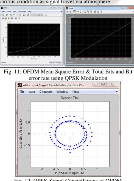
Fig. 11: OFDM Mean Square Error & Total Bits and Bit error rate using QPSK Modulation
[image:3.595.57.291.294.454.2] [image:3.595.309.544.450.766.2]As we know that for a better system mean square error must be minimum. As process carried out in digital form and we have to transmit bit in binary form with help of various generator from Simulink library. In figure 11 one graph represent MSE and other show bit error rate of OFDM QPSK. When we simulate our programme then we can see these data on display of Simulink system
Table 2: BER and SNR Modulation Schemes in OFDM System
As BER is depicted in table II: First of all binary PSK, OFDM system is modelled after that different type of modulation schemes comparison done and finally best one scheme is carried out using BER analysis and in this case QPSK modulation scheme is best for OFDM system.
C. UWB Block Diagram
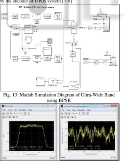
[image:4.595.52.281.137.244.2]Ultra-Wide Band is latest technology and its main advantageous is that work on high frequency for example 10GHz and that’s why data rate would be high and it also consist low bit error rate. UWB transmission would be through multipath fading and AWGN transmission channel. Cyclic Redundancy Check and RS Encoder schemes utilized by the encoder of UWB system [7-9]
[image:4.595.314.539.311.755.2]Fig. 13: Matlab Simulation Diagram of Ultra-Wide Band using BPSK
Fig. 14: Simulation Result of Transmitted & Received Signal of UWB in Matlab using BPSK
Figure 14 represents the spectrum of transmitted signal and received signal of UWB BPSK at oscilloscope. When information or data passed through atmosphere different types hazardous condition occurred and due to which information distorted or can say fading effect occurred.
Fig. 15: UWB Mean Square Error & Total Bits and Bit error rate using BPSK Modulation
As we know that for a better system mean square error must be minimum. As process carried out in digital form and we have to transmit bit in binary form with help of various generator from Simulink library. In figure 15 one graph represent MSE and other show bit error rate of UWB BPSK. When we simulate our programme then we can seen these data on display of Simulink system
Fig. 16: BPSK Signal Constellations of UWB
Table 3: BER and SNR Modulation Schemes in UWB System
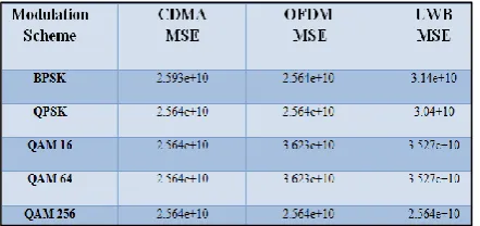
[image:4.595.60.540.316.756.2] [image:4.595.46.300.418.749.2]Table 4: MSE of Different Modulation Schemes for CDMA, OFDM and UWB System
V. CONCLUSION
In dissertation work our main focus is to compare result of different schemes UWB, OFDM and CDMA and which are further classified into digital modulation scheme. First of all simulation block diagram are essential for these and after that main tedious task to design smart antenna so that quality of service could be provided. Matlab 2013a used for our research work and using Communication tool box simulation block diagram are designed. After that smart antenna was designed which was most difficult task of our thesis work? After that bits are transmitted and received and receiver and then finally BER calculated. If BER would be least then that scheme would be considered best one and vice versa, besides this signal to noise ratio also analysed in DB. Considering various parameters like BER, SNR, constellation diagram and Mean Square Error and analysing finally we are able to compare different digital modulation technique and conclusion carried out for best one. Quadrature phase shift keying modulation technique is best one for OFDM and Quadrature Amplitude Modulation is best for Code Division Multiple Access and Ultra-Wide Band system having minimum Bit Error Rate.
REFERENCES
[1] Theodore S. Rappaport, “Wireless Communications Principles and Practice” 2nd ed., India: PHI Private Limited, pp. 458 – 459, 2008.
[2] Fazel & S. keiser, “Multi Carrier and Spread Spectrum Systems” 1st ed., England: John Wiley and Sons Limited, pp. 30 – 37, 2003.
[3] Lejiang Guo, Weijiang Wang, Guoshi Wang and Jian Cui, “Research and Implementation of Forest Fire Early Warning System Based on UWB Wireless Sensor Networks”, IEEE 2nd International Conference on Communication Systems, Networks and Applications, Vol. 1, pp. 176 – 179, 2010.
[4] Namsuk Lee, Yongseouk Choi, Sookjin Lee and Nam Kim, “A New CDMA-Based Bandwidth Request Method for IEEE 802.16 OFDMA/TDD Systems”, IEEE 2010 Communications Letters, Vol. 14, pp. 124 – 126, 2010.
[5] Wenshuo Zhang, Weixia Zou, Bin Li, Zheng Zhou, Feng Zhao and Zhiwei Wang, “On coexistence between UWB and OFDM-MIMO systems ”, IEEE International Conference on Ultra-Wideband, Vol. 2, pp. 1 – 4, 2010. [6] Xue Li, Ruolin Zhou, Chakravarthy V., Hong S. and
Zhiqiang Wu, “Total Intercarrier Interference Cancellation for OFDM Mobile Communication
Systems”, 7th IEEE Consumer Communications and Networking Conference, pp. 1 – 5, 2010.
[7] Fangni Chen, Shiju Li, “Proposal of a novel punctured LDPC coding scheme for Ultra-Wide Band system”, IEEE 7th International Symposium on Antennas, Propagation and EM Theory, pp. 1 – 4, 2009.
[8] Leonardo Betancu, Narcis Cardona, Andres Navarro and Lara Traver, “A Statistical Channel Model for On Body Area Networks in Ultra-Wide Band Communications”, IEEE Latin – American Conference on Communications, pp. 1 – 6, 2009.
[9] Ali Kotti, Zouhair Ben Jemaa and Safya Belghith,
“Performance of Asynchronous DS-UWB
Communication System On Rayleigh Multipath And AWGN Channel Versus Spreading Sequences”, IEEE 6th International Multi Conference on Systems, Signals and Devices, pp. 1 – 6, 2009.
[10]Maninder Singh and Prabhjot Kaur, “Performance Analysis of OFDM and UWB Systems on Basis of BER Using Simulink”, International Journal of Engineering Research and Technology, ISSN 0974 – 3154, Vol. 3, Number 3, pp. 711 – 719, 2010.
[11]Maninder Singh, Rajiv Kumar, Vinod Kumar and Sarla Kumari, “Comparison of CDMA and OFDM Using Simulink”, International Journal of Wireless Communication and Simulation, Vol. 2, Number 1, pp. 39 – 50, 2010.