warwick.ac.uk/lib-publications
Manuscript version: Author’s Accepted Manuscript
The version presented in WRAP is the author’s accepted manuscript and may differ from the
published version or Version of Record.
Persistent WRAP URL:
http://wrap.warwick.ac.uk/125034
How to cite:
Please refer to published version for the most recent bibliographic citation information.
If a published version is known of, the repository item page linked to above, will contain
details on accessing it.
Copyright and reuse:
The Warwick Research Archive Portal (WRAP) makes this work by researchers of the
University of Warwick available open access under the following conditions.
Copyright © and all moral rights to the version of the paper presented here belong to the
individual author(s) and/or other copyright owners. To the extent reasonable and
practicable the material made available in WRAP has been checked for eligibility before
being made available.
Copies of full items can be used for personal research or study, educational, or not-for-profit
purposes without prior permission or charge. Provided that the authors, title and full
bibliographic details are credited, a hyperlink and/or URL is given for the original metadata
page and the content is not changed in any way.
Publisher’s statement:
Please refer to the repository item page, publisher’s statement section, for further
information.
Reliable Many-to-Many Routing in Wireless Sensor
Networks Using Ant Colony Optimisation
Jasmine Grosso
Department of Computer ScienceUniversity of Warwick
Coventry, United Kingdom [email protected]
Arshad Jhumka
Department of Computer ScienceUniversity of Warwick
Coventry, United Kingdom [email protected]
Matthew Bradbury
WMGUniversity of Warwick
Coventry, United Kingdom [email protected]
Abstract—Wireless sensor networks (WSNs) have been widely studied in the context of many-to-one communication, in which multiple data sources send messages to a dedicated sink. However, there has been little research in the area of many-to-many communication. Many-to-many communication in WSNs is a growing application area, with examples including fire detection in both natural and urban areas, and the monitoring of heating and air conditioning within buildings. In this paper, we propose a scalable many-to-many routing protocol that makes use of Ant Colony Optimisation (ACO) that is applicable for an arbitrary number of sources and sinks. The protocol aggregates data sent from multiple sources into a single, sharedbackboneof nodes to reduce the total number of packets sent and so increase network lifetime. Results from simulations using the Cooja Network simulator show that the protocol is able to achieve packet delivery ratios above 95%, with the algorithm becoming more efficient with larger networks, sending fewer packets relative to the size of the networks, as well as involving fewer nodes in routing.
Index Terms—Wireless Sensor Networks; Many-to-Many Rout-ing; Ant Colony Optimisation
I. INTRODUCTION
Wireless sensor networks (WSNs) form the basis of many applications in increasingly connected environments. Low in power consumption, sensor nodes are deployed in large numbers in many types of environment, both urban and natural. Application areas of WSNs are numerous, and include habitat monitoring [1], healthcare [2], and environmental monitor-ing [3]. Traditionally, WSNs have been studied and applied in many-to-one scenarios, where many sensor nodes gather environmental data to forward them towards one dedicated node, called asink, in a process called convergecast. However, with the advent of novel systems, such as wireless sensor and actuator networks [4] and the Internet of Things (IoT), that are deployed in an increasing number of settings and environments, many-to-many communication within the network becomes necessary. A large amount of research has been carried out for many-to-one communication in WSNs, but many-to-many communication is still not widely studied.
A common scenario requiring the use of many-to-many communication in WSNs is a network in which multiple actuators are used to respond to environmental changes. Home automation is a possible application area of these wireless sensor and actor networks [4], with smart devices in the home such as thermostats, lightning, or other appliances acting
as sensors and actuators [5, 6]. A similar scenario is that of temperature control in office buildings and other high rises. Multiple actuators controlling air conditioning or heating systems will receive information from multiple sensors placed within rooms of the building, allowing control of airflow. This can also lead to reduced emissions from the building, as the environment control becomes more energy efficient [5]. Such applications will require a routing protocol capable of dealing with multiple sources and multiple sinks.
A number of solutions for many-to-many communications in WSN have been presented, however they generally have a number of issues. They are often not very scalable, for instance needing periodic, network wide broadcasts for network topology updates. This is inefficient and can lead to a reduction in network lifetime. Additionally, this can mean that the protocol does not react well to change, as the topology may become out of date. We present a routing protocol that communicates largely in the local neighbourhood and does not keep track of the global topology. This makes the protocol scalable, efficient, and adaptive to changes in the network. This protocol uses Ant Colony Optimisation [7], a heuristic algorithm based on the movements of ants in a colony. A
backboneof nodes is formed, where data is aggregated along a shared path in order to reduce the total number of packets that are sent in routing from sources to sinks.
The remainder of the paper is as follows: In Section II we present a selection of related work. Section III describes our problem specification and our ACO based routing algorithm is presented in Section IV, including a description of the implementation. Section V explains the experimental set up and Section VI presents the results of simulations. Finally, Section VII presents concluding remarks.
II. RELATEDWORK
A. Routing in Many-to-One WSN
PEGASIS is a chain based protocol similar to LEACH, with the sensor nodes forming a chain [9]. PEGASIS assumes that each node has global knowledge of the network, making the algorithm centralised. In [10], Oyman and Ersoy study sink placement in clustered wireless sensor networks, and find solutions to the problem of choosing which nodes should act as clusters.
Collection Tree Protocol builds trees routed at the sink. Data from a source travels up the tree to reach that sink [11]. Often CTP involves network wide broadcasts to keep topological information up to date, which can be energy expensive. An ACO based protocol should not require such broadcasts as a centralised view of network topology is not required.
B. Routing in Many-to-Many WSN
Directed Diffusion is a data centric protocol in which nodes receive interests, initiating data gathering for that interest [12]. Data is drawn back through the network to the requesting node via gradients. Similarly to the ACO protocol presented here, Directed Diffusion is largely determined by localised interactions and reinforces successful paths between source and sink. Directed Diffusion does this by sending additional messages to reinforce good routes and negatively reinforce bad routes, but with ACO, reinforcement of good paths is a natural outcome through the process of pheromone evaporation.
With the Rumor routing protocol, queries are routed to where the event occurs, as opposed to flooding the network [13]. Long lived agents create paths directed to events, and will optimise these paths when they encounter better routes. When two agents meet, they are also able to aggregate paths between multiple events. The use of long lived agents is similar to the use of ants in the ACO protocol presented here. Rumor Routing maintains only one path from source to sink, making it less adaptable to topology changes in the network than an ACO based protocol would be. In the case of node failure, Rumour routing relies on agents from other events repairing the single route from source to sink, but in ant based routing, ants should route around any failures. Rumor routing relies upon each node maintaining forwarding information to events. ACO does not require such list, rather only making decisions with local neighbour information when choosing which node to forward to, meaning memory overhead is lower.
Multisource Multisink Trees for Energy-Efficient Routing (MUSTER) is a distributed many-to-many routing protocol that merges independently built trees from source to sink [14]. The result is a shared path, or backbone, between the merged trees, that will split at the last possible node in order to send packets to both sinks. This backbone formation is similar to what takes place in the ACO protocol developed here, however MUSTER requires periodic network wide broadcasts to refresh trees in order to account for topology changes. The ACO based protocol presented here does not need this network wide refreshing of routes, using less energy and fewer packets sent.
C. Ant Colony Optimisation in WSN
Ant Colony Optimisation was originally defined by Dorigo et al. [7]. The heuristic approach can be used to provide near
optimal solutions to NP hard problems, with the advantage of being versatile and robust. ACO has been applied in the context of wireless sensor networks, but rarely does existing work investigate its use on networks with multiple sources and sinks [15].
An early example of the use of ACO in networks is AntNet [16], a distributed protocol for routing in communications networks. The protocol builds routing tables for each node, which direct messages towards the next node in the network. The use of AntNet is not focused on wireless sensor networks but IP (Internet Protocol) datagram networks. Zhang et al. extends this work to apply the protocol to wireless networks, and introduces three variations upon it [17], making use of flooding. These variations on the AntNet routing protocol does not take into account multiple sinks, a generally involve a large amount of packets sent.
In [18] ACO is applied to wireless sensor networks with the goal of finding short paths to route messages, and therefore minimising the amount of energy expended. The protocol, Energy-Efficient Ant-based Routing Algorithm (EEABR), runs for some iterations before a routing tree is built. The main goal of EEABR is to reduce energy consumed by the sensor nodes, as opposed to the protocol described in this report where fault tolerance and reducing the number of packets sent is prioritised. An example of a centralised ant based routing protocol is put forward with the AntChain algorithm [19]. Assuming that every node can communicate with the sink, AntChain forms low a low cost chain from sensors to the sink.
De Castro et al. present a method for using ACO in wireless sensor networks for computing minimum Steiner trees [20]. First, an offline centralised method is described, then an online distributed version. The algorithm forms a minimum Steiner tree that is rooted at the sink, and this tree can then be used for routing from sources to the sink. The tree is formed when two ants launched from source nodes towards the sink meet and combine to form a single ant. The testing of the algorithm is focused on a single sink node.
III. PROBLEMSPECIFICATION
In this paper, we focus on the problem of routing data from multiple sourcess1, . . . , sk to multiple sinks∆1, . . . ,∆l such that a minimum number of nodes are involved in routing. The problem is a variant of the vehicle routing problem which is known to be NP-hard [21]. Thus, in general, heuristics are required to provide solutions for different problem instances. However, heuristics are problem specific and are typically greedy in nature. This can lead to instances where the solution space is not properly explored, and the heuristic usually gets trapped in a local optimum and fails, in general, to obtain the global optimum solution. For this reason, we pursue the use of what is called meta-heuristic. Meta-heuristics are heuristics that are problem-independent. Thus, they do not take advantage of any specific properties of the problem at hand. In general, they are not greedy. In fact, they may even accept a temporary deterioration of the solution, allowing them to do a better
Symbol Definition
pi,j Probability of ant travelling from nodeito nodej
τi,j Pheromone value between nodeiand nodej
ηj Average hop counts for nodej
εj Hop range to sinks for nodej
α,β,γ Constants indicating the weight ofτi,j,ηj, andεj
N(i) The neighbours of nodei routea The route taken by anta
∆τt Change in pheromone value; used during evaporation
lr Route length from sources to sinks (number of nodes)
lb Backbone length (number of nodes)
B Constant indicating weight oflb
ρ Constant defining rate of pheromone evaporation
C Maximum number of cycles
hn,i Smallest hop count for nodentowards any sinki
[image:4.612.50.298.52.229.2]s Length of timer waiting for multiple ants to be received on the same node. Used to form backbone.
Table I: Symbol Definitions
exploration of the solution space to avoid getting trapped at local optima.
In this paper, as we focus on constructing a routing protocol, we useant colony optimisationas meta-heuristic to solve the problem. We explain the technique in more detail in the next section.
IV. THEORY
A. Ant Colony Optimisation
Ant Colony Optimisation is a heuristic algorithm based on the movements of ants in a colony. In nature, ants will travel towards a desired destination, such as a food source, while dropping a pheromone on the ground. Subsequent ants will then follow the pheromone trails left by ants, preferring routes with a higher level of pheromone. As the pheromone will evaporate over time, shorter routes are reinforced more, and so ants tend to follow these routes [7].
The protocol developed in this paper represents ants as packets being sent through the network, travelling on a multihop basis from the sources to the sinks. Every node will keep track of its neighbours using a linked list which also contains a pheromone value associated with each neighbour. Each ant chooses the next node to travel to using a probability function. The ants keep a memory of the route which is used to prevent repeat visits to the same node. When the ant reaches a sink, it is converted into a backward ant, which then uses the ant memory to travel backwards through the network to the original sources following the same route as the forward ant, updating the variable ∆τ, as it passes through each node. The update value depends on the success metrics of the forward route. The pheromone value is also periodically reduced to account for evaporation. Forward ants are launched periodically from the sources, with the time between each launch referred to as a
cycle.
In addition to the base ACO implementation, the protocol also aims to combine ants in order to aggregate data. When the multiple forward ants meet on the same node (within some
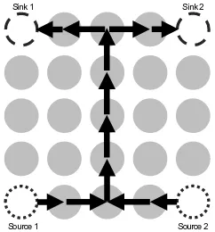
Source 1 Source 2
[image:4.612.377.498.53.183.2]Sink 1 Sink 2
Figure 1: Example of a 5x5 network with a backbone formed.
time periods), these ants are combined into a single ant. This combined ant then travels along a shared path, orbackbone
for a long as possible, before splitting into several ants again such that all sinks are visited. An example network with such a backbone is shown in Figure 1. Through this aggregation of messages, the total number of packets sent will be less, thus improving network lifetime.
B. Distributed Implementation
This protocol has been implemented using ContikiOS, an operating system designed for the Internet of Things [22]. In this implementation, each node only has information about its immediate neighbours, with no knowledge of overall network topology. Our implementation of a distributed version of ACO for many-to-many Wireless Sensor Networks is informally described below:
1) A set up phase takes place where each node sends local broadcasts to identify neighbours. Each node, i, keeps track of its neighbours using a linked list, denotedN(i), which also stores the pheromone values to the neighbours. Hop counts to sinks are also established during this phase, and also stored in N(i). Hop counts were chosen as the distance metric so that recalculation would not be necessary. Each node maintains this knowledge of hop counts for itself and its neighbours throughout.
2) Initially set all pheromone values to be some constant c. Set a time variabletto be 1 and cycle count variable to be 1. A cycle is defined to be the time between each periodic broadcast of ants.
3) Forward ants are periodically launched from the source nodes. Ants are implemented as messages being sent between nodes in the network. Each ant,a, has a stored ant memory containing the route, denoted routea. We argue that this is not restrictive as the route length is expected to be quite short, which we show later. 4) The forward ant chooses the next node to travel to with
probability:
pi,j=
[τi,j]α·ηj1β·εj1γ
P
k∈N(i)
[τi,k]α·ηk1 β·εk1γ
∀j /∈routea
0 otherwise
where pi,j is the probability that the ant a will travel from node i to node j, τi,j is the pheromone value between nodei and nodej,ηj is the average hop count to the sinks for nodej,εj is the hop range to the sinks for node j. α, β, and γ indicate the weight of these parameters.routea indicates the memory of antaand N(i)represents the neighbours of nodei.
5) When a node has received messages from multiple ants within timesof each other, the data is aggregated and a single ant is forwarded, forming the backbone. This ant continues choosing nodes with Equation 1. Currently, the backbone ants do not wait for more messages from other sources to combine into the backbone.
6) The backbone ant will travel until it reaches a node where there are no possible neighbours to travel to that will decrease the hop counts for all sinks. At this point, the backbone ants will split into individual forward ants again. This is implemented using a broadcast, that is received on all neighbouring nodes. Neighbouring nodes that are not already part of the forward path, that is those that are not inroutea, will continue travelling towards the sinks. After the backbone is split, the probability of travelling to a neighbouring node becomes Equation 2, taking into account the smallest hop count to any sink.
pi,j=
[τi,j]α·hj1β
P
k∈N(i)
[τi,k]α·hk1 β
∀j6∈routea
0 otherwise
(2)
wherepi,jis the probability that the antawill travel from nodeito nodej,τi,j is the pheromone value between nodei and nodej, andhj is the smallest hop count to any sink for node j. αand β indicate the weights of these parameters.routea indicates the memory of ant a andN(i)represents the neighbours of nodei.
7) Once the ants reach the sinks, they are transformed into backward ants. If a forward ant has reached a sink without having formed a backbone, backward ants are not generated, so that only paths where a backbone is formed are reinforced. Backward ants follow the reverse ofroutea, travelling back to the source nodes. The first backward ant to reach the backbone continues along it, such that only one backward ant traverses the backbone, with subsequent ants halting. At the end of the backbone the backward ant is split and continue to the sources using a broadcast. As the backward ants travel, they update a value in the neighbours list, ∆τ, which represents the change in pheromone value, using:
∆τt= ∆τt−1+
1 lr+ (lb·B)
(3)
where∆τt indicates the change in pheromone value at current timet,lrrepresents the total forward route length, including the multiple routes to and from the backbone, lb is the length of the backbone, andB is the weight of the backbone length.
8) The pheromone value is periodically updated every 128 seconds, an amount of time approximately relating to one cycle, using the equation:
τt= (ρ·τt−1) + ∆τt (4)
whereτtrepresents the pheromone value at timet,ρ∈ [0,1]indicates the rate of evaporation, and ∆τ is the trail change value.
9) Increment the cycle count by 1,t by 1, and launch one ant from each source node.
The protocol is described further in Algorithms 1, 2, and 3. Algorithm 1 is continually ran by all nodes in the network, with the current node represented asnode. If a forward ant is received, then Algorithm 2 is used; similarly Algorithm 3 is called when a backward ant is received on a node.
Algorithm 1 Description of ACO Protocol
1: procedureACO-PROTOCOL
2: cycle←0
3: t←0
4: cyclemax←C
5: whilecycle < cyclemaxdo
6: messages←0.The number of messages received by this node 7: ifnode∈sourcesthen
8: Choose next noden∈neighbourswith Eqn (2)
9: Initiate forward ant memory,routea.A list of visited nodes
10: routea←node
11: Send message fromnodetowardsn, with packetbufroutea
12: ifnodereceives a forward antthen
13: FORWARDANTRECEIVED()
14: else ifnodereceives a backward antthen
15: BACKWARDANTRECEIVED()
16: Evaporate pheromone betweennodeandnwith Equation 4
17:
V. EXPERIMENTALSETUP
The protocol has been developed using ContikiOS, an open source operating system for the internet of things [22]. Simulations were performed using Cooja [23], a network simulator for Contiki, using emulated Sky motes with UDGM radio medium. The source code1 and raw results2can be found
online. The protocol is compared with flooding; comparison with more state of the art protocols is difficult due to the lack of protocols dealing with multiple sources and multiple sinks.
A. Network Configuration
All experiments were performed using a square grid of nodes of sizen×n, wheren∈ {5,7,9,11,13}. The distance between nodes and transmission range is set up such that only horizontal and vertical neighbours can communicate. Experiments have been carried out using two sources and two sinks, with the sources and sinks fixed in the corners of the grid. The two sources are in the lower two corners and the two sinks in the upper two corners. An example configuration is shown in Figure 1. The configuration chosen at the start remains constant until the end of the experiment. Forward ants were launched from the sources periodically using a timer, both sources launch
1https://bitbucket.org/jasminegrosso/jg-contiki-public, commit 2019-03-11
2https://zenodo.org/record/2609159
Algorithm 2 Description of Forward Ant Protocol
1: procedureFORWARDANTRECEIVED
2: Addnodeto ant memory
3: routea←node
4: messages←messages+ 1
5: ifnode∈sinksthen
6: Reverseroutecto form backward ant memoryroutebw
7: Choose next noden, the node inrouteaafternode
8: Launch backward ant; send message fromnodetowardsn, with
packetbufroutebw
9: else
10: ifBackbone has not been formedthen
11: ifmessages6=|sources|then
12: Storerouteainternally
13: Set a timer forsseconds.
14: whileTimer is not yet finisheddo
15: Wait
16: ifmessages6=|sources|then
17: messages←0
18: Choose next nodenwith probability (2)
19: Send message towardsn, with packetbufroutea
20: else .Form the backbone
21: Combinerouteawith other stored routes to formroutec.
22: Choose next nodenwith probability (2)
23: Send message towardsn, with packetbufroutec
24: else
25: if∃n∈N(n)→(∀i∈sinks→hn,i< hnode,i)then
26: Choose next nodenwith probability (1)
27: Send message towardsn, with packetbufroutec
28: else .Split the backbone
29: Send|sinks|messages fromnodeto the neighbours with
the smallesthn,ifor any sink, with packetbufroutec
30:
Algorithm 3 Description of Backward Ant Protocol
1: procedureBACKWARDANTRECEIVED
2: bwmessages←bwmessages+ 1
3: Update change in pheromone with equation (3)
4: ifnode∈sourcesthen .Backward ant route complete
5: Stop ant, send no more messages.
6: else
7: ifnodeis the first node of the backbone inroutebwthen
8: ifbwmessages >1then
9: Stop ant, send no more messages
10: else ifnodeis the last node of the backbone inroutebwthen
11: Broadcast messages tonode∈N(n)wherenode∈routebw
12: else
13: Choosenthe next node inroutebw
14: Send message towardsnwith packetbufroutebw
ants at the same rate. Approximately 500 runs of each setup will be performed on the simulator. Each run is finished when 115 cycles have been completed; insufficient cycles will lead to that run being excluded from the results.
B. Parameters
The ACO based protocol involves setting a number of parameters. The three factors for choosing the next node are pheromone, average hops, and hop range. Pheromone indicates that previous ants have followed this route before, with higher values indicating more successful routes. The average hops directs ants generally towards the sinks, so nodes with lower average hops are preferred. Hop range was chosen for the probability function as this will help to form the backbone; a lower hop range indicates themiddleroute between sinks, and
so it is more likely for ants to meet. Each factor is weighted using the impact parameters, which were set to be4,1, and 4 respectively, for all network sizes. These parameters were found to be most effective through repeated testing.
Backbone length is a factor for pheromone updates; longer backbones are encouraged, so more pheromone is laid. Back-bone length impact was set to be1. Additionally, route length is also used when updating the trail change, as we wish to encourage shorter routes overall.
The evaporation constant was set to be 0.8, which leads to the pheromone value dropping very little between cycles, leading to fast convergence on a route.
VI. RESULTS ANDDISCUSSION
To determine success we will examine the following per-formance metrics:
• Delivery Ratio: The ratio between total messages sent and total messages successfully received. With the setup here, this is the ratio between all messages sent launched from both sources and all messages received at both sinks. • Number of nodes involved: The mean number of nodes
involved in the communication from sources to sinks, as a percentage of total number of nodes in the network. • Packets Sent per cycle: The number of packets sent in
a cycle. This includes packets sent by both forward and backward ants, but excludes packets sent during the set up phase.
• Backbone length: The mean number of nodes in the backbone formed. A longer backbone is considered more successful, as benefits from the advantages of data aggregation to a greater extent.
[image:6.612.50.304.56.503.2]• Backbone Convergence: The converged backbone for an experiment is considered to be the backbone that most routes follow on that experiment. A higher percentage of experiments following its converged route is more successful.
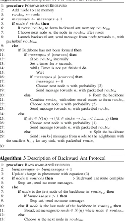
Figure 3 shows that the ACO routing protocol achieves a high mean delivery ratio for all network sizes, indicating the consistent delivery of messages from both sources to both sinks. The average delivery ratio is 93.3% between network sizes. Additionally, the standard error in the delivery ratio shown in Figure 2a is very small, which shows consistency between experiments performed at each network size. The delivery ratio remains similar between network sizes, but falls slightly at the largest network size of 169 nodes. This could be due to difficulty in forming the initial backbone, or just due to the necessity for more packets needing to be sent overall leading to more failures in delivery. The timer used for combining ants into a backbone remained constant between network sizes, so delivery ratio may be improved with increasing this timer. Despite this, the protocol still has a high delivery ratio consistently between network sizes.
● ● ● ● ● ●
● ● ●
●
0 25 50 75 100
25 49 81 121 169
Network size (nodes)
Mean Deliv
er
y Ratio (%)
Protocol
ACO Flooding
(a) Mean Delivery Ratio
● ●
● ●
●
● ●
● ●
●
0 50 100 150 200 250
25 49 81 121 169
Network size (nodes)
Mean P
ack
ets Sent P
er Cycle
Protocol
ACO Flooding
(b) Mean Packets Sent Per Cycle
● ●
● ●
●
● ●
● ●
●
0 10 20 30 40 50
25 49 81 121 169
Network size (nodes)
Nodes In
v
olv
ed
Protocol
ACO Flooding
(c) Nodes Involved in Routing from all sources to all sinks
●
●
●
● ● ●
●
●
●
●
0 20 40 60
25 49 81 121 169
Network size (nodes)
Nodes In
v
olv
ed (% Netw
or
k Siz
e)
Protocol
ACO Flooding
[image:7.612.134.477.46.363.2](d) Nodes involved in routing as a percent-age of network size
Figure 2: Experimental results
protocol. Similarly, when looking at the nodes involved in routing, Figure 2c the ACO protocol uses more nodes as the network size increases, but this increase is not linear, indicating scalability. Figure 2d show that with an increase in network sizes, the percentage of nodes involved decreases.
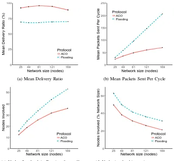
When analysing the role of the backbone in routing for the ACO protocol, we found that the backbone length increased in larger network sizes, as shown in Figure 3a. This is expected, as the larger network size necessitates a larger number of hops from source to sink. However, when looking at the backbone length as a percentage of the total network size, this now decreases with larger networks. We believe that this shows the scalability of the protocol, as larger networks benefit from the data aggregation of the backbone to a greater extent. This is collaborated with Figure 2b, showing that the packets sent increases with network size, but the size of this increase is less with larger networks. When considering the length of the backbone in proportion to the maximum distance between a source and a sink, Figure 3c, we see that a similar decrease happens, again indicating the scalability of the algorithm.
Figure 3d shows that the backbone is successfully formed the majority of the time for all network sizes. The success rate is lower for smaller networks, which may indicate that ants tend towards the sinks when they are relatively close. There is also a drop in the creation of backbone with the largest
network size, which may be due to similar issues regarding delivery ratio. In some cases the backbone is formed more than once in a cycle, leading to a percentage higher than 100%, however this is a very rare occurrence and is not considered to be affecting the running of the protocol in the vast majority of cycles.
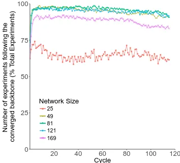
[image:7.612.137.290.46.352.2]Backbone convergence is investigated in Figure 4 and Figure 3e. Figure 4 shows that experiments tend to converge on a backbone at approximately the third cycle. Ants then tend to follow that converged backbone through subsequent cycles to the end of the experiment, indicating a persistent route. The converged backbone is defined as the backbone that is followed by ants for the majority of the experiment. The smallest network size of 25 nodes has more variation in convergence than larger networks as well as a lower convergence rate, which may be caused by similar issues involving backbone creation shown in Figure 3d. Figure 3e shows the percentage of cycles that follow the converged backbone route. Similar issues occur with the smallest network size, however a large proportion of cycles follow the converged backbone for other sizes. There is a small drop for larger network sizes, consistent with other metrics.
When comparing the ACO with flooding, the equivalent network tested with a flooding protocol achieved on average lower delivery ratios and more packets sent overall. The flooding protocol achieved an average delivery ratio of 69.2%,
● ●
● ●
●
0 5 10 15 20
25 49 81 121 169
Network size (nodes)
Mean Length of Backbone
(a) Mean length of the converged backbone formed
●
●
●
●
●
0 5 10 15 20
25 49 81 121 169
Network size (nodes)
Mean Length of Backbone
(% Netw
or
k Siz
e)
(b) Mean length of converged backbone as a percentage of network size
●
●
●
●
●
0 20 40 60
25 49 81 121 169
Network size (nodes)
Mean Length of Backbone (% Max Distance)
(c) Mean Backbone Length as a percentage of the maximum distance between a source and a sink
● ●
● ●
●
80 85 90 95 100 105
25 49 81 121 169
Network size (nodes)
Backbone Created
(% Number of Cycles)
(d) Number of times the route backbone was created as a percentage of number of cycles
● ●
● ●
●
0 25 50 75 100
25 49 81 121 169
Network size (nodes)
P
ercentage of Cycles f
ollo
wing the
con
v
erged backbone
[image:8.612.59.568.56.432.2](e) Percentage of cycles where the con-verged backbone was being followed by ants.
Figure 3: Experimental results
which is significantly lower than the ACO protocol. This indicates that the ACO protocol improves over existing methods for many-to-many routing, and that the protocol is reliable for a number of network sizes. The packets sent increases with network size, but at a significantly slower rate that the equivalent increase of the flooding based protocol. We believe that this shows that the ACO protocol is scaleable, and becomes more efficient with larger networks in terms of packets sent. A similar trend is seen with the nodes involved in route, shown in Figures 2c and 2d.
VII. CONCLUSION ANDFUTUREWORK
We present a routing protocol based on ant colony op-timisation that is capable of routing in networks consisting of multiple sources and multiple sinks. The main advantage of the protocol is the ability to combine messages into a single backbone, taking advantage of data aggregation and minimising the number of nodes involved in routing. Results have shown the protocol to have high delivery ratios while sending relatively few packets that improves upon equivalent results using flooding.
● ● ●
●●●●●●●●●●●●●●●●●●●●●●●●●●●●●●●●●●●● ●●●●●●●
● ●●●●●●●●
●●●●●●●●●●●●●●●●●●●●●●●●●●●●●●●●●●●● ●●●●●●●●●●●●●
●●● ●●●●●●●
0 25 50 75 100
20 40 60 80 100 120
Cycle
Number of e
xper
iments f
ollo
wing the
con
v
erged backbone (% T
otal Exper
iments)
Network Size
● ● ● ● ●
25 49 81 121 169
Figure 4: Number of Experiments following the converged backbone as a percentage of total experiments.
[image:8.612.348.525.467.627.2]of the protocol, and how it recovers in such situation where links fail. In doing this, we hope to show the fault tolerance using ACO. In addition to this, the effect on changing the network topology on the effeciveness of the protocol will be tested. This will include varying the number of sources and sinks, and changing source and sink placement away from the corners of the network. We will also investigate adaptations for energy conservation.
ACKNOWLEDGEMENT
This work was funded by the UK Engineering and Physical Sciences Research Council (grant no. EP/L016400/1) via the EPSRC Centre for Doctoral Training in Urban Science.
REFERENCES
[1] A. Mainwaring, D. Culler, J. Polastre, R. Szewczyk, and J. Anderson, “Wireless sensor networks for habitat monitoring,” inWSNA ’02. ACM, 2002, pp. 88–97. [2] A. Milenkovi´c, C. Otto, and E. Jovanov, “Wireless sensor
networks for personal health monitoring: Issues and an implementation,”Comput. Commun., vol. 29, no. 13-14, pp. 2521–2533, Aug. 2006.
[3] L. Oliveira and J. Rodrigues, “Wireless sensor networks: A survey on environmental monitoring,”JCM, vol. 6, pp. 143–151, 04 2011.
[4] I. F. Akyildiz and I. H. Kasimoglu, “Wireless sensor and actor networks: research challenges,”Ad Hoc Networks, vol. 2, no. 4, pp. 351–367, 2004.
[5] I. F. Akyildiz, W. Su, Y. Sankarasubramaniam, and E. Cayirci, “A survey on sensor networks,”IEEE Commu-nications Magazine, vol. 40, no. 8, pp. 102–114, 2002. [6] E. M. Petriu, N. D. Georganas, D. C. Petriu, D. Makrakis,
and V. Z. Groza, “Sensor-based information appliances,”
IEEE Instrumentation Measurement Magazine, vol. 3, no. 4, pp. 31–35, Dec 2000.
[7] M. Dorigo, V. Maniezzo, and A. Colorni, “Ant system: optimization by a colony of cooperating agents,”IEEE Transactions on Systems, Man, and Cybernetics, Part B (Cybernetics), vol. 26, no. 1, pp. 29–41, Feb 1996. [8] M. J. Handy, M. Haase, and D. Timmermann, “Low
energy adaptive clustering hierarchy with deterministic cluster-head selection,” in4th International Workshop on Mobile and Wireless Communications Network, 2002, pp. 368–372.
[9] S. Lindsey and C. S. Raghavendra, “Pegasis: Power-efficient gathering in sensor information systems,” in
Proc., IEEE Aerospace Conference, vol. 3, March 2002, pp. 3–3.
[10] E. I. Oyman and C. Ersoy, “Multiple sink network design problem in large scale wireless sensor networks,” in
2004 IEEE International Conference on Communications, vol. 6, June 2004, pp. 3663–3667 Vol.6.
[11] O. Gnawali, R. Fonseca, K. Jamieson, D. Moss, and P. Levis, “Collection tree protocol,” inSenSys 2009. New York, NY, USA: ACM, 2009, pp. 1–14.
[12] C. Intanagonwiwat, R. Govindan, D. Estrin, J. Heidemann, and F. Silva, “Directed diffusion for wireless sensor networking,” IEEE/ACM Transactions on Networking, vol. 11, no. 1, pp. 2–16, Feb. 2003.
[13] D. Braginsky and D. Estrin, “Rumor routing algorthim for sensor networks,” inProc. of the 1st ACM International Workshop on Wireless Sensor Networks and Applications, ser. WSNA ’02. New York, NY, USA: ACM, 2002, pp. 22–31.
[14] L. Mottola and G. P. Picco, “Muster: Adaptive energy-aware multisink routing in wireless sensor networks,”
IEEE Transactions on Mobile Computing, vol. 10, no. 12, pp. 1694–1709, Dec 2011.
[15] M. Saleem, G. A. D. Caro, and M. Farooq, “Swarm intelligence based routing protocol for wireless sensor networks: Survey and future directions,” Information Sciences, vol. 181, no. 20, pp. 4597–4624, 2011, special Issue on Interpretable Fuzzy Systems.
[16] G. Di Caro and M. Dorigo, “Antnet: Distributed stigmer-getic control for communications networks,” Journal of Artificial Intelligence Research, vol. 9, pp. 317–365, 01 1999.
[17] Y. Zhang, L. Kuhn, and M. Fromherz, “Improvements on ant routing for sensor networks,”Ant Colony Optimization and Swarm Intelligence, pp. 154–165, 01 2004.
[18] T. Camilo, C. Carreto, J. S. Silva, and F. Boavida, “An energy-efficient ant-based routing algorithm for wireless sensor networks,” in5th International Conference on ACO and Swarm Intelligence, ser. ANTS’06, 2006, pp. 49–59. [19] N. Ding, P. X. Liu, and C. Hu, “Data gathering com-munication in wireless sensor networks using ant colony optimization,” inIEEE/RSJ International Conference on Intelligent Robots and Systems, Aug 2005, pp. 697–702. [20] L. De Castro, F. Von Zuben, G. Singh, S. Das, S. V. Gos-avi, and S. Pujar,Ant Colony Algorithms for Steiner Trees, Jan. 2005, pp. 181–206.
[21] J. K. Lenstra and A. H. G. R. Kan, “Complexity of vehicle routing and scheduling problems,” Networks, vol. 11, no. 2, pp. 221–227, 1981.
[22] A. Dunkels, B. Gr¨onvall, and T. Voigt, “Contiki - a light-weight and flexible operating system for tiny networked sensors,” inLocal Computer Networks, 2004. 29thAnnual IEEE International Conference on, 2004, pp. 455–462. [23] F. Osterlind, A. Dunkels, J. Eriksson, N. Finne, and
T. Voigt, “Cross-level sensor network simulation with cooja,” in 31st IEEE Conference on Local Computer Networks, Nov. 2006, pp. 641–648.
[24] R. Lim, F. Ferrari, M. Zimmerling, C. Walser, P. Sommer, and J. Beutel, “Flocklab: A testbed for distributed, synchronized tracing and profiling of wireless embedded systems,” inIPSN, Apr. 2013, pp. 153–165.
[25] C. Adjih, E. Baccelli, E. Fleury, G. Harter, N. Mitton, T. Noel, R. Pissard-Gibollet, F. Saint-Marcel, G. Schreiner, J. Vandaele, and T. Watteyne, “FIT IoT-LAB: A large scale open experimental IoT testbed,” in WF-IoT, Dec. 2015, pp. 459–464.