Abstract—This paper presents the modeling and control of a Wind Energy Conversion Systems (WECS) based Permanent Magnet Synchronous Generator (PMSG). The WECS adopts a back-to-back converter system with Voltage Source Inverter (VSI). In the strategy, the generator-side converter is used to tracks the maximum power point and the grid-side converter is responsible for the control of power flow and control the dc-link voltage. The control scheme uses a B-spline artificial neural network for tuning controllers when the system is subjected to disturbances. The currents from VSI’s are controlled in a synchronous orthogonal dq frame using an adaptive PI control. The B-spline neural network must be able to enhance the system performance and the online parameters updated can be possible. This paper proposes the use of adaptive PI controllers to regulate the current, frequency and DC link voltage. Simulation results show the feasibility and robustness of the proposed control schemes for PMSG based wind turbines. Comprehensive models of wind speed, wind turbine, PMSG and power electronic converters along with their control schemes are implemented in MATLAB/SIMULINK environment.
Keywords— Voltage-source inverter, neural network, power converters, PMSG.
I. INTRODUCTION
HE history of wind power goes back many centuries. Wind power is an unending energy source and clean. Compared with conventional energy, wind power does not requirement fuel and does not damage the environment. Wind energy technology has evolved rapidly over the last thirty years with increasing rotor diameters and the use of complex power electronics to allow operation at variable rotor speed [1].
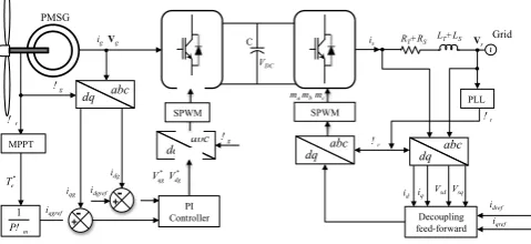
A WECS is a physical system that has three primary components. The first one is rotor connected to blades. As wind goes through blades, it makes the rotor rotate and therefore creates mechanical power. The second one is a transmission (gear box) that transfers power from the rotor to generator. The last one is electric generator that converts mechanical power to electric power [2], as shown in Figure 1.
This work was supported by PROMEP: Redes Temáticas de Colaboración under the project titled: Fuentes de Energías Alternas.
A. M. Omar and T. O. Ruben are with the Engineering Department at Polytechnic University of Tulancingo, Huapalcalco, Tulancingo, Hidalgo, CO 43629, Mexico, phone: 775-755-8319; fax: 775-755-8321; (e-mail: [email protected]).
S. S. Jose M. is with Centro de Investigación Avanzada en Ingeniería Industrial, Universidad Autonoma del Estado de Hidalgo, C. P. 42184 México; (e-mail: [email protected]).
The drivers behind these developments are mainly the ability to comply with Grid Code connection requirements and the reduction in mechanical loads achieved with variable-speed operation [1]. Different machine types have been used in WECS through the ages. These include the squirrel cage induction generator (SCIG), doubly fed induction generator (DFIG), and synchronous generator PMSG with power ratings from a few kilowatts to several megawatts. DFIG’s are widely used as the generator in a variable speed wind turbine system. But, the DFIG needs a gearbox to match the turbine and rotor speed. The gearbox many times suffers from faults and requires regular maintenance, making the system unreliable [3].
The reliability of the variable speed wind turbine can be improved significantly using a direct drive-based PMSG. This generator has the following main characteristics: (a) full operating speed range; (b) brushless; (c) full scale power electronic converter; (d) complete control of active and reactive power exchanged with the grid [4].
[image:1.595.307.547.555.665.2]Power electronics, being the technology of efficiently converting electric power, plays an important role in wind power systems. It is an essential element for integrating the variable speed wind power units to achieve high efficiency and high performance in power systems. In particular, VSI units are used to match the characteristics of wind turbines with the requirements of grid connections, including frequency, voltage, control of active and reactive power, harmonics, etc. [5].
Fig. 1 Wind energy conversion system using PMSG
Major techniques to regulate the VSI output current include either a variable switching frequency, such as the hysteresis control scheme, or fixed switching frequency schemes, such as the ramp comparison, stationary and synchronous frame proportional–integral (PI), optimal, nonlinear, predictive
-+
Grid C
VDC
Vt RT+RS LT+LS Vs
~
is
abc dq
id iq
r
Vsd Vsq
Decoupling feed-forward
abc dq
SPWM
g
mc ma mb
idref iqref
PLL
abc dq
r PMSG
SPWM
r
MPPT
PI Controller
abc dq
g ig Vg
1
Pm
Te* iqgref
iqg
-+
idg idgref
Vqg*Vdg*
On-Line Control Strategy for a WECS with
Permanent Magnet Synchronous Generator
Omar Aguilar, Jose M. Sausedo, Ruben Tapia,
Member, IAENG
control, and soft computing, neural networks control and on the fusion or hybrid of hard and soft control techniques [6]. However, tuning alternatives are needed for electrical grid complexity. Some author’s mixed neural networks and PID techniques to strengthen the linear controller. In [7], [8] a back propagation neural networks was used to adjust coefficients KP , KI, and KD of PID controllers attaining power regulation
of wind turbines. The similar PID tuning strategy using radial basis function (RBF) neural network for pitch angle control systems [9]. In these work we proposed a good adaptive tuning technique based on B-spline neural network (BSNN).
Typically, the VSC synchronization is usually done by a phase-locked loop (PLL) system. Nevertheless, having a good synchronization permits a good monitoring of the grid voltage phase and amplitude, and enhancing the capability of injecting power into the grid. A good PLL can provide further advanced functionalities to the control system, as it is the case of the islanding detection mode for wind farms [10-11].
In this paper a B-spline neural network (BSNN) is employed for two main tasks; one for PI simultaneous tuning, taking care of a key feature: the proposed controller must be able to enhance the system performance; the second the online parameters updated can be possible. The strategy is proposed to update conventional PI parameters for currently operating in power converters that were tuned time ago.
II. WIND ENERGY CONVERSION SYSTEM
A. Wind Turbine Model
A wind turbine is a power extracting mechanism. Wind turbine output power Pwt and wind turbine torque Twt are given
by the following equations [12]
Pwt0.5
v2R3C
p
(1.a)wt0.5Cp
v2R3
(1.b) where ρ is the air density, R is the blade length,
v
is the wind speed and Cp(λ) is the turbine performance coefficient,
hR/v,ω
h is the angular rotor speed for the wind turbine.The performance coefficient Cp is a function of the
tip-speed-ratio. Therefore, the Cp(λ) performance curve gives
information about the power. The torque coefficient is derived as
C
Cp
(2) The torque coefficient can be described by a polynomial function of the tip speed ratio as [13]
C
a0
2a1
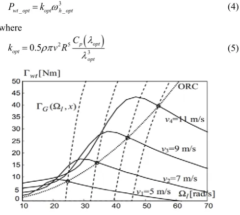
a2 (3) The output power characteristics of the wind turbine are depicted in Fig. 2.The wind turbine can produce maximum power when the turbine operates at maximum Cp(λopt). If the wind speed varies,
the rotor speed should be adjusted to follow the change. The
objective optimum power from a wind turbine can be written as
Pwt_optkopt
3h_opt (4)
where
kopt0.5v2R5Cp
opt3
opt
[image:2.595.306.551.108.327.2](5)
Fig. 2 Output power characteristics of wind turbine.
Therefore, the objective optimum torque can be given by wt_optkopt
2
h_opt (6)
The mechanical power generated by the turbine as a function of the rotor speed for different wind speed is shown in Fig. 2. The optimum power curve (Pwt_opt) shows how
maximum energy can be captured from random wind. If the controller can properly follow the optimum curve, the wind turbine will produce maximum power at any speed within the allowable range. [12-14].
B. Permanent Magnet Synchronous Generator Model The PMSG is modeled under the following simplifying assumptions: (a) sinusoidal distribution of stator winding; (b) electric and magnetic symmetry; (c) negligible iron; (d) losses; (e) and unsaturated magnetic circuit. The voltage and electromagnetic torque equations of the PMSM in the dq reference frames are given by the following equations [4,12-14]:
Lddid
dt RsidLqiqsvd (7.a)
Lqdiq
dt Rsiq
Ldidm
svq (7.b)where
v
d,v
q, id and iq are the d-q axis voltages and currents,respectively; Rs is the stator resistance; Ld and Lq are the d-q
axis inductances;
ω
s is the generator rotational speed; ψm is thepermanent magnetic flux. The electromagnetic torque is obtained as
Te3
2pmiq
LdLq
idiq (9)therefore the electromagnetic torque is,
T
e=pi
qψ
m. Using generator convention; the rotational speed of the generator and wind turbine driving torque as [12-14]Jdh
dt P
wtTeBh
(10)where Γwt is the turbine driving torque referred to the
generator (Γwt=Pwt/ωl), B is the active damping coefficient
representing turbine rotational losses and ωh= iωl, where i is
the ratio of a rigid drive train.
[image:3.595.313.432.82.115.2]III. BACK TO BACK CONVERTER SYSTEM MODEL
Figure 1 illustrates that back-to-back converter system can be considered as the composition of two VSC systems: (i) the right-hand side VSC system involves the real reactive power and DC-voltage controllers; (ii) and the left-hand side VSC system controlled the speed of the generator. The real-reactive power controller and the controlled DC-voltage power port are interfaced with grid and PMSG, respectively. The real-reactive-power controller and the controlled DC-voltage power port are connected in parallel from their DC-side terminals [15].
The WECSs are requested to operate robustly in different grid locations and to keep ancillary services in order to behave as a conventional power plant. The control scheme for the WECS based PMSG is designed to satisfy the grid requirements.
A. VSC Dynamic Model
Figure 1 depicts the diagram of a three-phase three-wire VSC connected to the AC system represented by an equivalent Thevenin circuit via the inductance and resistance (LT, RT) of
the coupling transformer. The converter DC terminal is connected to a shunt capacitance (Cdc) and resistance (Rdc),
which represent losses switching losses. The three-phase AC side voltage balancing equations of the VSC are expressed as [16]:
dIabc
dt
1 LsLT
RsRT
IabcVSabcVT (11)
where Iabc =[Ia Ib Ic]T is the three-phase current vector, VSabc
=[VSaVSb VSc]T is the three-phase AC source voltage vector,
VT =[VTa VTb VTc ]T is the voltage source converter AC
terminal three-phase voltage vector. The dc-side voltage dynamic expression is deduced based on power balance between the ac and dc-side as
Vdc
t Idc
t P t
PL
t (12)where P(t) is the instantaneous real power at point of common coupling voltage, and PL(t) includes the total power loss, and
Pdc = VdcIdc is the transferred power from the dc side to the
“converter” system. Loss components include: i) capacitor dielectric; ii) switching and on-state; and iii) losses in the converter ac-side components as represented by Rdc. The DC
current is:
CdcdVdc
dt
Vdc
RdcIdcIabc T VT
Vdc
(13)
Using a orthogonal transformation, the state equations for the back-to-back are [16]:
did1
dt a1id11iq1b1Vsd1b1VTd1 (14.a) diq1
dt a1iq11id1b1Vsd1b1VTd1 (14.b)
did2
dt a2id22iq2b2Vsd2b2VTd2 (14.c) did2
dt a2id22iq2b2Vsd2b2VTd2 (14.d)
dVdc
dt
1
Cdc
Vdc
Rdc
1
Vdc
id1VTd1iq1VTq1
1Vdc
id2VTd2iq2VTq2
(14.e)
where a=( Rs+RT)/( Ls+LT), b=1/(Ls+LT), ω1=ωh, ω2 is grid
frequency, ix1 are currents of PMSG, Vsx2 are grid voltage, VTx2
are terminal voltage grid side converter. B. Instantaneous Complex Power (d-q)
The α-β or Clarke transformation offers advantages in the dimension order reduction. However, for feedback control implementation is highly desirable that the signals to be constant. The inverse Park transform allows, from constant values generating signals in-phase or anti-phase, respect to the reference. That is especially useful for flexible AC transmission systems (FACTS) and power conditioners’ control [17]. Complex instantaneous power can be expressed as [14-15,17-18]
S
VTdITdVTqITq
j V
TqITdVTdITq
(16)Equation (16) suggest that if VTq=0, the active and reactive
power components are proportional to id and iq, respectively.
This property is widely employed in the control of grid-connected three-phase VSC systems [14-15,17-18]. The angle
θ of the grid voltage is computed and provided by a phase-locked loop [17-18].
IV. CONTROL WECS-BASED ON PMSG
The main advantage of the back-to-back converter is that it allows independently handle the active and reactive power flow between two AC systems with different characteristics (fundamental frequency, switching frequency, input voltage, etc.).
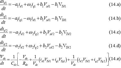
A. Generator Side Converter Control
The inner loops are constituted by two controllers, which regulate the dq-axis of the stator currents. The electromagnetic torque may be controlled directly by the q-axis current component iq, therefore the speed can be controlled by
changing q axis current, and d-axis current component id is set
[image:3.595.313.550.158.292.2]dq axis stator voltage references, which are sent to the sinusoidal pulse-width modulation (SPWM) block as show in Fig 3. The SPWM will generate the switching signals required by the IGBT elements of the converter.
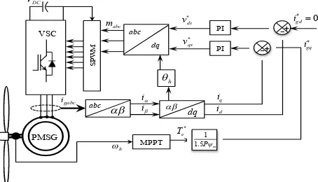
B. Grid Side Converter Control
The control scheme of this strategy is exhibited in Fig. 4. The grid-side converter control aim is to supply a reliable electric power to the consumers, following a specific set of parameters such as voltage, frequency and harmonic levels. The control scheme contains two cascaded loops. The inner loops independently control the grid id and iq currents, while
the outer loops control the DC-link voltage, the reactive and active power. The feedback and feed-forward signals are first transformed to the dq frame and then processed by compensators to produce the control signals [12,18]. These control signals are transformed to the abc frame and sent to the grid side converter.
Under normal conditions the wind turbine’s reactive power output is controlled under the range according to the grid codes. This work proposes the use of adaptive PI controllers to maintain the current and frequency AC load and DC link voltage constant. Reactive power flow should be maintained close to zero. Both parameters the proportional and integer gains are updated online to attain a proper performance under different operating conditions, without restructuring the control scheme.
V. CONTROLLER TUNING
The proposed can be achieved adding a B-spline neural network to update kP and kI gains in five PI controllers, Fig.
3-4, where each PI transfer function is given by, U(s)
E(s) kIkP
s (17) Thus, kP and kI are updated from a B-spline neural network at
[image:4.595.312.550.85.204.2]every sampled time.
Fig. 3 Generator-side converter control system.
The B-spline neural networks (BSNN’s) are a particular case of neural networks that allow to control and model systems adaptively, with the option of carrying out such tasks on-line, and taking into account the power grid non-linearities.
Fig. 4 Grid-side inverter control system.
The BSNN’s output can be described by [19],
yaTw (18.a) ww1w2 w; aa1a2 a (18.b) where
w
γ anda
γare the
γ-th weight and the γ -th BSNN basisfunction output, respectively; γ is the number of weighting factors.
In this paper it is proposed that
k
P andk
I be adapted through one B-spline neural network, respectively, for each voltage source converter. The dynamic control parameters for back to back system can be described as follows:kPNNm
ex,wm
(19.a) kINNm
ex,wm
(19.b) where NNm denotes the B-spline network which is used tocalculate
k
P andk
I; wm is the corresponding weighting factor;m=1,2,3,4,5 number of PI controllers. Fig. 5 depicts a scheme of the proposed B-spline neural network.
The appropriate design requires the following a-priori information: the bounded values of ex, the size, shape, and
overlap definition of the basis function. Such information allows to bound the BSNN input and to enhance the convergence and stability of the instantaneous adaptive rule [19]. Likewise, with this information the BSNN estimates the optimal weights’ value. The neural network adaptive parameters, (19) are created by univariate basis functions of order 3, considering that ex are bounded within [-12, 12].
On-line learning of continuous functions, mostly via gradient-based methods on a differentiable error measure is one of the most powerful and commonly used approaches to train large layered networks in general [20], and for non-stationary tasks in particular.
In this application, the parameters' quick updating is looked for. While conventional adaptive techniques are suitable to represent objects with slowly changing parameters, they can hardly handle complex systems with multiple operating modes. The instantaneous training rules provide an alternative so that the weights are continually updated and reach the convergence to the optimal values. Also, conventional nets sometimes do not converge, or their training takes too much time [19-20].
Te*
VDC
igabc
PMSG
SPW
M
abc ii dq
iq
id
dq abc
VSC
h mabc
1 1.5Pm
PI
PI
-+
-+
v*
ds
igq
igd
0
v*
qs
h MPPT
vsq
vsd
AC
System Qsr
*
VDC
Vsabc
SPW
M
abc vs
vs
dq iq
id
-+
dq abc
VSC
s
mabc
md
mq +
Lg
Lg
PI
PI
-+
-+
ud
uq
iq
LC Filter
abc
dq
iabc
PQ controller
Psr
+
+ +
id PI
-+
VDC
+ +
[image:4.595.49.276.538.668.2]Fig. 5. Proposed BSNN for adapting ܭ and ܭூ control parameters.
In this paper, the neural network is trained on-line using the following error correction instantaneous learning rule [18],
wi
t wi
t1 ei
ta
t2
2ai
t (20)where η is the learning rate and ei(t) is the instantaneous
output error.
Respect to the learning rate, it takes as initial value one point within the interval [0, 2] due to stability purposes [20]. This value is adjusted by trial-and-error. If η is set close to zero, the training becomes slow. On the contrary, if this value is large, oscillations may occur. In this application, it settles down in 0.051 for
k
P , and 0.0016 fork
I.It is proposed that during the actualization procedure, a dead band is included to improve the learning rule convergence. The weighting factors are not updated if the error has a value below 0.1%,
wi
t wi
t1 ei
ta
t2
2ai
t , if ei 0.0001wi
t1, otherwise
(21)
This learning rule has been elected as an alternative to those that use, for instance, Newton’s algorithms for updating the weights [21] that require Hessian and Jacobian matrix evaluation. Regarding the weights’ updating, (15) should be applied for each input-output pair in each sample time; the updating occurs if the error is different from zero. That is the reason because it is said that the weights converge to optimal values [20]. Hence, the BSNN training process is carried out continuously on-line, while the weights’ values are updated using only two feedback variables.
VI. TEST RESULTS AND ANALYSIS
In order to demonstrate the feasibility of this proposition, a WECS-Based on PMSG is employed. Matlab-Simulink are used for simulation, the proposed tuning performance is exhibited. To analyze the results, simulations are developed under different scenarios with PI controllers tuned by BSNN (dynamic parameters). Some operating conditions are taken into account. The models of the low-power (3-kW) rigid drive PMSG based WECS shown in Fig. 1 are included in the simulations.
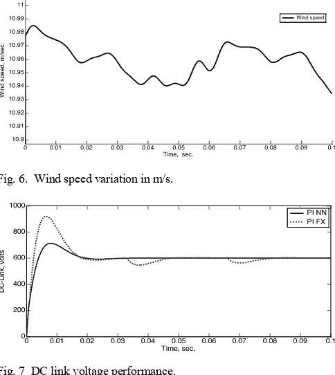
Major system parameters are listed in Table 1 [13]. The power converter and the control algorithm are also implemented and included in the model. The sampling time used for the simulation is 20 μs. The wind speed profile is considered varying smoothly with step rate at different slopes, as see in Fig. 6. The system is subjected to the following sequence of events: until t = 0.033 s, Pref = 2200 W, Qref = 0.
At t = 0.033 s, Psref is subjected to a step change from 2200 to
1800 W. At t = 0.66s, Psref is subjected to another step change
from 2200 to −1500 W.
Table 1
Parameters of PMSG wind power system. Blade length: R= 90 m
Rated Line-Line Voltage 4000 volts Rated Stator Current 490 Amperes Rated Power Factor 0.7162 Rated Mechanical Torque 58.4585 kNm Stator Resistance Rs = 24.21 mΩ
No. of poles p=8
Stator inductance Ld=Lq=9.816 mH
Magnet flux linkage ψm=4.971 Wb
Figure 7 shows the simulation result of DC link voltage with the proposal and considering fixed parameters. Fig. 8 exhibits the dynamic behavior of the reactive power at DC link bus, where the proposed scheme is worked. The transient response is diminished in terms of overshot magnitude without parameters update.
[image:5.595.307.549.418.689.2]Fig. 6. Wind speed variation in m/s.
Fig. 7 DC link voltage performance.
The adaptive neural network PI exhibits very well performance adapting itself to the new conditions. Fig. 8 illustrates that Ps and Qs rapidly track Psref and Qsref,
respectively.
1
w
2
w
t
e
input basis functions weight vector output
1
a
2
a
P
Fig. 8 Active and reactive power in WECS terminals.
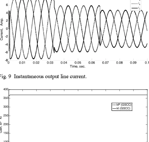
Fig. 9 shows the instantaneous load currents when the load changes. The load current is changing with the load variations as expected. From Fig. 9, it is seen that there is no significant rise in the current waveform during load transient. Fig. 10 displays the proportional an integral gain’s evolution for controller one. Quite similar results are exhibited for all adaptive parameters.
Fig. 9 Instantaneous output line current.
Fig. 10 Proposed BSNN for adapting kI and kP parameter, controller
3.
VII. CONCLUSION
The aim of the paper is to show the performance of adaptive PI parameters as a mean to enhance VSC performance. In order to attain such purposes a BSNN control is proposed. With this neural adaptive scheme, the possibility to implement the on-line updating parameters is potential due to it has learning ability and adaptability.
Simulation results shown that the system has a stable operation at various load conditions. Unlike the conventional
technique, the BSNN exhibits an adaptive behavior since the weights can be adapted on-line responding to inputs and error values as they arise.
REFERENCES
[1] O. Anaya-Lara, N. Jenkins, J. Ekanayake, P. Cartwright and M. Hughes,
Wind Energy Generation Modelling and Control, United Kingdom: Wiley, 2009, pp. 110-112.
[2] T. Ackermann, Wind Power in Power Systems, England, Wiley, 2005 [3] B. Wu, Y. Lang and S. Kouro, Power Conversion and Control of Wind
Energy Systems, USA, IEEE Press, 2011.
[4] I. Boldea, Variable Speed Generators, Florida USA, CRC Press Taylor & Francis Group, 2006.
[5] G. Abad, J. López, M. A. Rodríguez, L. Marroyo and G. Iwanski,
Doubly Fed Induction Machine, New Jersey: Wiley, 2011, pp. 1-25. [6] Hoa M., and D. Subbaram N., “Advanced Control Strategies for Wind
Energy Systems: An Overview”, in Power Systems (PSCE), 2011 International Conference on, Vol. 1, 2011, pp. 1-8.
[7] X. Yao, X. Su, and L. Tian, “Wind turbine control strategy at lower wind velocity based on neural network PID control,” in Intelligent Systems and Applications, 2009. ISA 2009. International Workshop on, pp. 1 –5, May. 2009.
[8] Z. Xing, Q. Li, X. Su, and H. Guo, “Application of BP neural network for wind turbines,” in Intelligent Computation Technology and Automation, 2009. ICICTA ’09. Second International Conference on, vol. 1, pp. 42 –44, Oct. 2009.
[9] X. Yao, X. Su, and L. Tian, “Pitch angle control of variable pitch wind turbines based on neural network PID,” in Industrial Electronics and Applications, 2009. ICIEA 2009. 4th IEEE Conference on, pp. 3235 – 3239, May. 2009.
[10] A. Luna, J. Rocabert, G. Vazquez, P. Rodríguez, R. Teodorescu and F. Corcoles, “Grid Synchronization for Advanced Power Processing and FACTS in Wind Power Systems”, in Proc. 2010 IEEE Industrial Electronics Conf., pp. 2915-2920.
[11] A. Valderrabano and J. M. Ramirez, “Details on the implementation of a conventional StatCom’s control,” presented at the Int. Conf. IEEE. Transmission and Distribution: Latin America, Bogota, Colombia, 2008. [12] A. Uehara, A. Pratap, T. Goya, T. Senjyu, A. Yona, N. Urasaki and T. Funabashi, “A Coordinated Control Method to Smooth Wind Power Fluctuations of a PMSG-Based WECS”, IEEE Trans on Energy Conversion, Vol. 26, No. 2, pp. 550-558, June 2011.
[13] I. Munteanu, A. Iuliana B., N. A. Cutululis, and E. Ceanga, Optimal control of Wind Energy Systems, London, Springer, 2008.
[14] E. Haque, M. Negnevitsky, and K. M. Muttaqi, “A Novel Control Strategy for a Variable-Speed Wind Turbine With a Permanent-Magnet Synchronous Generator”, IEEE Trans. on Industry Applications, Vol. 46, No. 1, pp. 331-339 Jan./Feb. 2010.
[15] L. Shuhui, T. A. Haskew, R. P. Swatloski, and W. Gathings, “Optimal and Direct-Current Vector Control of Direct-Driven PMSG Wind Turbines,” IEEE Trans. on Power Electronics, Vol. 27, No. 5, pp. 2325-2337, May 2012
[16] J. Arrillaga, Y. Liu, N. Watson and N. Murray, Self-Commutating Converters for High Power Applications, United Kingdom: Wiley, 2009. [17] J. C. Rosas, “Simple Topologies for Power Conditioners and FACT’s
Controllers,” Ph.D. dissertation, Cinvestav, Guadalajara, 2009.
[18] A. Yazdani and R. Iravani, Voltage-Sourced Converters in Power Systems Modeling, Control, and Applications, New Jersey: Wiley, 2010. [19] Brown, and C. Harris, “Neurofuzzy Adaptive Modeling and Control,”
Prentice Hall International, 1994.
[20] D. Saad, “On-line learning in neural networks,” Cambridge University Press 1998.
[image:6.595.48.288.343.572.2]