ISSN (Print) : 2320 – 3765 ISSN (Online): 2278 – 8875
I
nternational
J
ournal of
A
dvanced
R
esearch in
E
lectrical,
E
lectronics and
I
nstrumentation
E
ngineering
(An ISO 3297: 2007 Certified Organization)
Website: www.ijareeie.com
Vol. 6, Issue 2, February 2017
DsPIC Based Speed Control of Three Phase
Induction Motor Using V/F Method
Dr.K.Kannan Kaliappan1, S.Anusiya2, K.Kavipriya3, R.Logeswari4, V.Suganya5
Associate Professor, Dept. of EEE, V.S.B Engineering College, Karur, Tamilnadu, India1
UG Student, Dept. of EEE, V.S.B Engineering College, Karur, Tamilnadu, India2,3,4,5
ABSTRACT:This paper presents design and development of a three phase induction motor drive using IGBTs at the inverter power stage with volt hertz control (v/f) in closed loop using dsPIC30F5011 as a controller. It is a 16bit high performance digital signal controller(DSC). DSC is a single chip embedded controller that integrates a controller attributes of a controller with a computation and through put capabilities of a DSP in a single core. A 1.5HP, 3-phase, 415V, 50Hz induction motor is used as load for the inverter. Digital Storage Oscilloscope Textronix TDS2024B is used to record and analyse the various waveforms. The experimental results for V/F control of three phase induction motor using dsPIC30F5011 chip clearly shows constant volts/hertz and stable inverter line to line output voltage.
KEYWORDS: Digital Signal Controller (DSC), microcontroller (MC), Pulse width modulation (PWM), variable frequency drives (VFD)
I.INTRODUCTION
.
Fig.1 PLC block diagram
Fig.2 Block Diagram of the System
The various factors which make the microcontroller based system attractive are, 1. Improved reliability and increased flexibility.
2. Simplicity of implementation in variable speed drives 3. Low cost and high accuracy
4. Possible to change torque speed characteristics of drive by software modification.
The simplicity of this project is that it can be operate by any person who need not know microcontroller programming.
ISSN (Print) : 2320 – 3765 ISSN (Online): 2278 – 8875
I
nternational
J
ournal of
A
dvanced
R
esearch in
E
lectrical,
E
lectronics and
I
nstrumentation
E
ngineering
(An ISO 3297: 2007 Certified Organization)
Website: www.ijareeie.com
Vol. 6, Issue 2, February 2017
In this system, control kernel DSC accept velocity and which is fed by photoelectric encoder, associating with the space vector algorithm to drive module IGBT, and use keyboard to set parameter and use numeral tube to display electric-mechanic velocity real time.
The system is designed as motor control system for driving medium power, 3-phaseAC induction motor. The digital signal controller dsPIC30F5011 is used in this work. The dsPIC30F5011 device contains extensive Digital Signal Processor (DSP) functionality within high performance bit microcontroller (MCU) architecture. The use of this 16-bit Digital Signal Controllers yields enhanced operations, fewer system components, lower system cost and increased efficiency. The conventional approach of this work is to first convert the line voltage AC into DC. DC is again converted to single/three phase AC as per load requirements. The output voltage, frequency or both of inverter can be controlled by the application of power electronics and digital signal controller. The output voltage waveforms of the inverter should be sinusoidal. The speed control is undertaken by using variable frequency method. The frequency is varied by controlling the switching (on/off) of power IGBTs in the inverter. According to the requirement, a software program is written and is fed to the digital signal controller (dsPIC30F5011) for the necessary action. The controller circuit essentially takes the output frequency of the inverter, the set speed and actual speed of the motor into account. Depending upon the difference between the set speed and actual speed, the digital signal controller decides the frequency of gate pulse of IGBTs. The filter circuit is added at the output of the inverter.
Frequency control with flux proportional to V/f and voltage proportional to the speed seems to be the best solution. PWM gives a high quality output voltage using DSPIC.
Three phase inverter output gives a better feed to the induction machine without extra components needed by the motor and also produces a higher starting torque and reduced speed pulsation amplitude.
Fig.4 Block diagram of a variable speed control system
The relationship between synchronous speed, rotor speed and the slip is given by
S = (Ns – Nr) / Ns
Nr = Ns (1-S)
Rotor speed Nr = 120f (1-S) / p
ISSN (Print) : 2320 – 3765 ISSN (Online): 2278 – 8875
I
nternational
J
ournal of
A
dvanced
R
esearch in
E
lectrical,
E
lectronics and
I
nstrumentation
E
ngineering
(An ISO 3297: 2007 Certified Organization)
Website: www.ijareeie.com
Vol. 6, Issue 2, February 2017
Fig.6 Feedback Circuit for 3-Phase Induction Motor
Speed Control Methods
frequency ratio [3].
V/F Control of Three Phase Induction Motor
The constant Volts Hertz control methods is the most popular method of Scalar control, controls the magnitude of the variable like frequency, voltage or current. The control system is illustrated in Fig. 1 when stator frequency fails under a given frequency threshold (boost frequency).
The voltage magnitude must be kept at given level called boost voltage to keep rotor flux magnitude constant. Vboost
means small voltage is added to dc voltage reference to compensate stator resistance drop at low frequency. At opposite when frequency becomes higher than rated value, the voltage magnitude is kept at rated value, the stator flux is no more constant & torque decreases.
The characteristic is
Y ∝ Φ × 2πf
Φ ∝ V/f
ISSN (Print) : 2320 – 3765 ISSN (Online): 2278 – 8875
I
nternational
J
ournal of
A
dvanced
R
esearch in
E
lectrical,
E
lectronics and
I
nstrumentation
E
ngineering
(An ISO 3297: 2007 Certified Organization)
Website: www.ijareeie.com
Vol. 6, Issue 2, February 2017
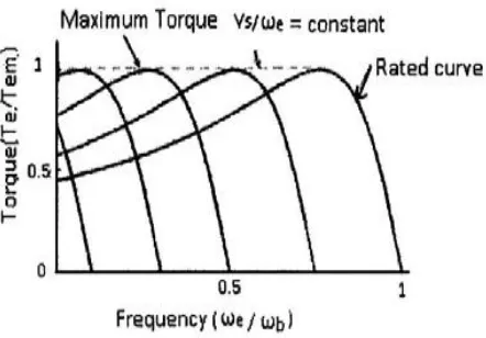
Fig. 7 Torque Speed characteristics of the induction motor Other than variation in speed, the torque speed characteristics of V/F control reveal the following:
• The starting current requirement is lower.
• Since almost constant rated torque is available over the entire operating range, the speed range of the motor becomes wider. User can set the speed as per the load requirement, thereby achieving the higher efficiency.
• The stable operating region of the motor is increased. Instead of simply running at its base rated speed (NB), the
motor can be run typically from 5% of the synchronous speed (NS) up to the base speed. The torque generated by can be kept constant throughout in this region.
Because of above reasons, V/F control method is used in this work.
Implementation of V/F Controlled Induction Motor Drive
System Overview: The block diagram of the proposed three phase induction motordrive using V/F control is shown in
Fig. 3[5]. It has three phase full bridge rectifier, three phase full bridge inverter, control circuit, speed sensing circuit and output filter. In the proposed work, single phase KBPC3510 Rectifier Module is used instead of power diodes. Two single phase bridge rectifier modules KBPC3510 are so connected to make them 3-phase bridge rectifier module. The output of the rectifier is filtered by using 220µF, 900V capacitors. The three phase inverter has 6-FGA25N120ANTD-IGBT’s switches with the snubber circuit for each switch. The output of inverter is filtered by using filter. The output of the filter is applied to the three phase induction motor. The digital control of motor is achieved by applying gate pulses from the control circuit to each of the IGBTs switch through opto-isolation.
Power circuit design: The power circuit contains rectifier assembly, inverter assembly and output filter. During the starting as rotor is stationary there is no back EMF and hence motor draws heavy current which will be 5 to 6 times that of the rated current. Hence to limit this heavy current starter is used. Initially, for a period of 3 seconds relays insert the resistors in each phase to limit the heavy current flow and later on when the induction motor draws the rated current, relays bypass the resistors
D. Control Unit:
The control circuit of the proposed scheme consists of a Digital Signal Controller dsPIC30F5011.A Digital Signal Controller (DSC) is a single-chip, embedded controller that seamlessly integrates the control attributes of a Microcontroller (MCU) with the computation and throughput capabilities of a Digital Signal Processor (DSP) in a single core. The DSPIC, DSC has the “heart” of a 16-bit MCU with robust peripherals and fast interrupt handling capability and the “brain” of a DSP that manages high computation activities, creating the optimum single-chip solution for embedded system designs. The dsPIC30F devices contain extensive Digital Signal Processor (DSP) functionality within high-performance 16-bit microcontroller (MCU) architecture. It also consists of six opto-coupler for isolating the control and power circuits. In this work an opto-coupler TLP250is used to isolate the gate drive circuit and the IGBT-based power circuit. Six IGBTs of the power circuit are controlled by the PWM signals generated by the control circuit.
E. Experimental Setup and Results
The proposed control system is implemented by a DSC (dsPIC30F5011) based PWM inverter. C language is used to develop the program. The device is programmed using MPLAB Integrated Development Environment (IDE) tool. It is a free, integrated toolset for the development of embedded applications employing Microchip's PIC and DSPIC controllers. For execution of C-code, MPLAB compiler is used. In this work 415v, 50Hz, 3-Ph, 1.5 HP Induction motor is used.
The photograph of complete hardware setup is shown in Fig. 5. Closed loop control of induction motor is carried out for different loads and speeds. For different loads and set speeds, current drawn by the motor and actual speed of the motor are noted and are tabulated. Tektronix TDS2024B Digital Storage Oscilloscope (DSO) is used to store gate pulses and voltage waveforms.
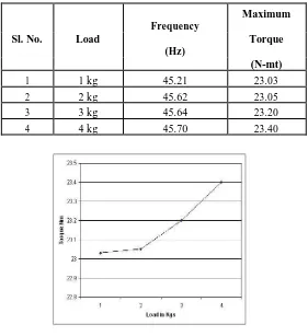
It is observed that the maximum torque almost remains constant irrespective of change in load for particular set RPM. As torque almost remains constant the actual speed also remains constant which is almost near to set speed with an error of +/- 20 RPM.
Table 1. Experimental Results for setspeed as 1350 rpm
Frequency
Maximum Sl. No. Load Torque
(Hz)
(N-mt)
1 1 kg 45.21 23.03
2 2 kg 45.62 23.05
3 3 kg 45.64 23.20
4 4 kg 45.70 23.40
ISSN (Print) : 2320 – 3765 ISSN (Online): 2278 – 8875
I
nternational
J
ournal of
A
dvanced
R
esearch in
E
lectrical,
E
lectronics and
I
nstrumentation
E
ngineering
(An ISO 3297: 2007 Certified Organization)
Website: www.ijareeie.com
Vol. 6, Issue 2, February 2017
Fig.9 Maximum Torque Vs Load
VI.CONCLUSION
From table 1 and Fig.8 the control of three-phase induction motor has been presented. This complete system is developed and tested in power electronics laboratory. Speed control of motor is acquired with the accuracy of ±20 rpm. The selected rpm is locked irrespective of change in load. The drive is operated at an input voltage of three phase 415v and the corresponding readings of the stator voltage, stator current, rectifier output voltage and frequency values at different speeds are taken. With the variation of stator voltage, frequency is also varied proportionally, such that V/F ratio is constant. The inverter line to line voltage recoded is very stable and very smooth compared to single-phase. Hence this three-phase induction motor V/F control by DSC is more stable, efficient and economical.
REFERENCES
1. J. Liu and S. Mekhilef, H.Li, “Effective Induction Motor Controller Based Voltage/frequency”, IEEE Trans, Industry Applications, 2009. 2. Kannan Kaliappan,“VFD Based Speed Control of Three Phase Induction Motor Application for Paper Manufacturing Industry”, Research
Journal of pharmaceutical, Biological and Chemical Sciences (RJPBCS), ISSN: 10975-8585, vol.8 (1),2017.
3. K. Sandeep kumar, K. Pritam satsangi, “Micro-Controller Based Closed Loop Control of Induction Motor Using V/F Method” IEEE Trans, Industry Applications, 2007.
4. Kannan Kaliappan,“ “High Performance MPPT Based on variable speed Generator driven by Wind Power Generation in Battery Applications”, Journal of Electrical and Engineering Technology, vol.9,no.1, pp. 205-213. ( ISSN: 1975-0102). 2014
5. Shahriar Mohammadi, “Speed Control of Three Phase Induction Motor Using Fixed Pattern PWM Wave”, IEEE Trans, Industry Applications, 1993.
6. C.S. Kamble, J.G Chaudhari M.V Aware, “Digital Signal Processor Based V/F Controlled Induction Motor Drive”, IEEE Trans, Industry Applications, 2010.
7. M.S.Aspalli,, Vinaya Kumar, P V Hunagund, Development and Analysis of Variable Frequency Three Phase Induction Motor Drive, IJ-ETA-ETS, July 10-Dec 10, Vol.3, Issue2:PP 189-195.
8. M.S.Aspalli, Veerendra.D and P.V.Hunagund, A New Generation VLSI Approach for V/F Control of Three-Phase Induction Motor, IJCSI International Journal of Computer Science Issues, Special Issue, ICVCI-2011, Vol. 1, Issue 1, November 2011: PP 7-12.
9. Thida Win, Nang Sabai, and Hnin Nandar Maung”Analysis of variable frequency three phase induction motor drive”. World academy of science, Engineering and technology 2008.
10.Masayuki Morimoto, Kiyotaka Sumito, Shinji Sato, Katsumi Oshitani, Shigeru Okuma” High efficiency, unity power factor VVVF drive system ofan induction motor” IEEE transactions on power electronics. Vol 6.No.3.July 1991.
11.Alfredo,Thomas A. Lipo and Donald W. Novotny, “A New Induction Motor V/f Control Method Capable of High-Performance Regulation at LowSpeeds” IEEE Trans. Industry Applications, Vol. 34, No. 4 July/ August 1998.