En-Cheng Wang* and Shao-Jie Cheng
Abstract—A hexagonal fractal antenna is presented for satellite navigation applications in this paper. The geometry of the antenna is inspired by the Sierpinski carpet and has compact dimensions, improved bandwidth, good radiation pattern due to the self-similar property of fractal geometry. The bandwidth ranging from 1.54 GHz to 1.61 GHz can work at L1 band of the Global Positioning System (GPS) and B1 band of the Beidou satellite navigation system (BDS). The simulated and measured gains show a good agreement over the bandwidth.
1. INTRODUCTION
Microstrip antenna, which has small size, low cost and easy processing characteristics, is widely used in the field of satellite communication and satellite navigation [1]. In recent years, with the development of multi-mode satellite navigation system, the design of satellite receiving antenna, which can receive multi-frequency signal, has become more and more important [2].
Fractal geometry is generated by iteration with the characteristic of self-similar geometric structures. It has similarity between entirety and local. The research finds that the fractal geometry is used for antenna design, showing size and frequency advantages [3, 4]. Fractal antennas have a striking feature that it can be applied to antenna designs to achieve goals of multiband, wideband, and size miniaturization. Many fractal structures such as Sierpinski carpet, Hilbert curve and Koch curve have been used for designing antennas [5, 6].
This paper proposes a hexagon-shaped microstrip fractal antenna for satellite navigation application. The radiating patch consists of a total of 43 hexagons within the original hexagon. Two feed lines are used to achieve circular polarization.
2. ANTENNA DESIGN
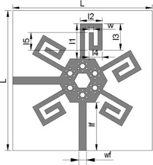
The patch of the proposed antenna consists of a hexagonal radiating element, five fan-blade-shaped radiating elements and two feed lines. The hexagonal radiating element is inspired by Sierpinski model. The original design was formed by cutting a square into nine squares, removing one or more sub-squares and continuing recursively. This process can be applied to any shape, and it is applied to a hexagon-shaped radiating element in this paper
The reason behind using the hexagonal radiator is that the bandwidth performance of a circular patch antenna is better than any other geometries. However, hexagonal geometry is approximately equal to circular patch [7]. So, the hexagonal fractal radiator was designed to achieve wideband.
Firstly, the construction of the hexagonal radiator begins with a regular hexagon. Secondly, the regular hexagon is transformed into seven sub-hexagons, and the central sub-hexagon is removed. Then, the same procedure is applied to the remaining six sub-hexagons, respectively. Eventually, the geometry
Received 9 July 2017, Accepted 6 September 2017, Scheduled 11 October 2017 * Corresponding author: Encheng Wang ([email protected]).
Figure 1. Recursive procedure of the hexagonal radiator.
of the third iteration is applied in this paper. The recursive procedure of the hexagonal radiator is shown in Fig. 1.
The proposed antenna is fed by microstrip lines, which give freedom to cut fractals on the surface of the antenna. To obtain the characteristic impedance of 50 ohms, following equations are used [8]:
Z0 =
120π
√ε
eff ×
W
h + 1.393 +
2 3ln
W
h + 1.444
εeff = εr + 1
2 +
εr−1 2
1 + 12 h
W
1 2
εeff is the effective dielectric constant W the width of the feed line, and h the height of the substrate from the ground plane.
Through the above equations, it is concluded that length and width of the antenna should be 23.37 mm and 2.46 mm, respectively. Because the dimension of antenna substrate cannot meet the required length, the feed line is matched with the antenna through a rectangular patch of length 3 mm at bottom of the antenna.
In order to realize circular polarization, duplex feeding with 90◦ phase difference is applied. It can produce two equal amplitudes and 90◦ phase difference of linear polarization electric field components. The five fan-blade shaped radiating elements can effectively increase the antenna’s electrical length and improve performance of the antenna. The dimension of five fan-blade-shaped radiating elements is determined by HFSS optimization design. The whole structure of the antenna proposed in this paper is shown in Fig. 2. The optimized dimensions are listed in Table 1. The dielectric constant of 1.6-mm-thick porcelain substrate material is 5.7, and the loss tangent is about 0.
Side length of the biggest hexagon, the hexagon in the center, the six small hexagons and the 36 tiny hexagons are 10 mm, 3.33 mm, 1.11 mm and 0.37 mm, respectively.
w 1.76 lf 19.34
wf 3
3. RESULTS AND DISCUSSION
3.1. Comparison of Simulation and Measurement Results
The fabricated hexagonal fractal navigation antenna is shown in Fig. 3. The comparison of simulation and measurement results is given in Fig. 4.
Figure 3. Fabricated hexagonal fractal navigation antenna.
Figure 4. Comparison of S11 for simulation and measurement results.
As shown in Fig. 4, the proposed antenna displays that return loss is below−10 dB at 1.575 GHz. It works well at GPS L1 band, and the bandwidth ranges from 1.54 GHz to 1.61 GHz. The relative bandwidth is 4.4%.
Figure 5 shows the plots of the simulated and measured radiation patterns in the E-plane at resonant frequencies. Major lobe covers most of the radiation pattern which makes the antenna useful. The gain in the direction of 0◦ is 2.017 dB.
Figure 6 shows a wide 3-dB axial ratio bandwidth of 0.87% at 1.575 GHz.
Fig. 7 shows RHCP higher than LHCP inE-plane. So, the proposed antenna exhibits a righthand circularly polarized radiation over the circularly polarized band.
According to the above figures, it is obvious that simulation and measurement results have little difference.
3.2. Effect of the Patch Shape
Figure 5. Comparison of radiation pattern for simulation and measurement results.
Figure 6. Comparison of axial ratio curves for simulation and measurement results.
Figure 7. Simulated RHCP and LHCP gain pattern of the proposed antenna.
Figure 8. Recursive procedure of the square radiator.
Figure 9. Recursive procedure of the triangular radiator.
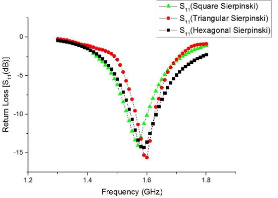
Figure 10. Return loss of the different shaped radiator.
Figure 11. Different hexagonal fractal antennas.
3.3. Effect of the Fractal Structure
In addition to the Sierpinski fractal, other fractal structures can also be used for hexagonal radiator. Four different fractal structures are shown in Fig. 11, which produce different results. Since two feed lines are used in this design, its structure will affect the integrity of the Minkowski fractal and the Giuseppe Peanao fractal. According to [9], the rectangular Koch fractal and triangular Koch fractal have responded at higher frequencies under the same dimension. So, the Sierpinski fractal is more conducive to achieve miniaturization than other fractal structures.
3.4. Investigation of the Contribution of the Fan-Blade Shaped Patch
Figure 12. Radiation pattern of the antenna without fan-blade structures in E-plane.
the gain of antenna, but also reduce the dimension of antenna. The percentage of miniaturization is 81.97%.
3.5. Effect of the Fan-Blade Width
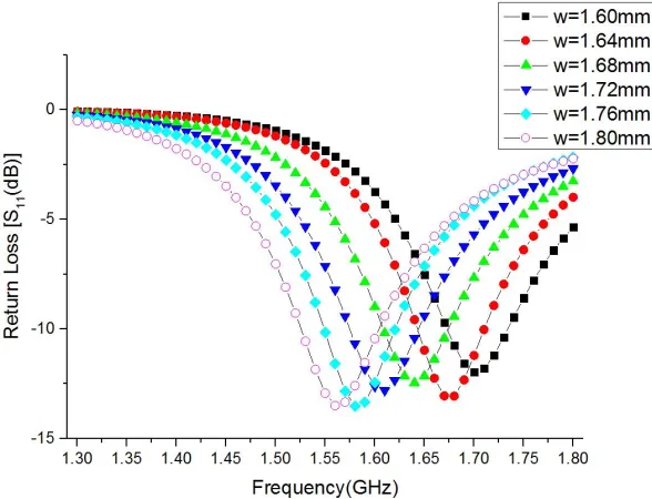
The width of fan-blade patches is optimized by HFSS. The proposed antenna is simulated for various fan-blade patch widths from 1.60 to 1.80 mm in steps of 0.04 mm. The results are shown in Fig. 13. As the width increases, resonant frequency of the proposed antenna decreases step by step. When the resonance occurs at around 1.575 GHz, the width of fan-blade patches is found at w= 1.76 mm.
Literature Impedance
bandwidth Gain AR bandwidth
Dimension (mm)
This paper 4.4% 2.02 dB 0.87% 56×56×1.6
Reference [10] 1.2% 1.45 dB 0.6% 100×100×21.6
Reference [11] 4% 2.2 dB 1% 70×70×2
Reference [12] 2.3% 4.33 dB 0.6% 80×80×7.8
Through the comparison, the proposed antenna in this paper has a great advantage over the other GPS navigation antennas. Impedance bandwidth and AR bandwidth of the proposed antenna are better than the antennas in [9] and [11]. The dimension of the hexagonal fractal antenna is the smallest of the four antennas.
4. CONCLUSION
In this paper, a hexagonal fractal antenna inspired by the Sierpinski carpet is presented. It has wide frequency band and compact dimension due to three fractal iterations. Through the results of simulation and measurement, the designed antenna works well at L1 band of the GPS and B1 band of the BDS. Radiation patterns of the proposed antenna in E-plane and H-plane perform well too. Circular polarization is realized by duplex feeding with 90◦ phase difference. The design is a very good contender for a satellite navigation antenna, and it has great advantages over other same type of antennas.
ACKNOWLEDGMENT
The research works in this dissertation are supported by Beijing Municipal Natural Science Foundation (4163073).
REFERENCES
1. Irteza, S., E. Sch¨afer, R. Stephan, A. Hornbostel, and M. A. Hein, “Compact antenna array receiver for robust satellite navigation systems,” International Journal of Microwave and Wireless Technologies, Jul. 2014.
2. Irteza, S., et al., “Four-element compact planar antenna array for robust satellite navigation systems,” IEEE 7th European Conference on Antennas and Propagation (EuCAP 2013), Gothenburg, Sweden, Apr. 2013.
3. Sawant, K. K. and C. R. Suthikshn Kumar, “CPW Fed Hexagonal Micro Strip Fractal Antenna for UWB Wireless Communications,” International Journal of Electronics and Communications (AE ¨U), Elsevier Publications, No. 69, 31–38, 2015.
4. Azari, A., “A new super wideband fractal microstrip antenna,” IEEE Transactions on Antennas and Propagation, Vol. 59, No. 5, 1724–1728, 2013.
6. Choukiker, Y. K., S. K. Sharma, and S. K. Behera, “Hybrid fractal shape planar monopole antenna covering multiband wireless communications with MIMO implementation for handheld mobile devices,” IEEE Transactions on Antennas and Propagation, Vol. 62, No. 3, 1483–1488, 2014. 7. Singhal, S. and A. K. Singh, “CPW-fed hexagonal Sierpinski super wideband fractal antenna,”IET
Microw. Antennas Propag., Vol. 10, No. 15, 1701–1707, 2016.
8. Potapov, A. A., “The base of fractal antenna theory and applications: Utilizing in electronic devices,” 2013 IX International Conference on Antenna Theory and Techniques (ICATT), 62, 67, Sept. 16–20, 2013.
9. Mondal, T., S. Samanta, R. Ghatak, and S. R. Bhadra Chaudhuri, “A novel tri-band hexagonal microstrip patch antenna using modified Sierpinski fractal for vehicular communication,”Progress In Electromagnetics Research C, Vol. 57, 25–34, 2015.
10. Hsieh, W.-T., T.-H. Chang, and J.-F. Kiang, “Dual-band circularly polarized cavity-backed annular slot antenna for GPS receiver,”IEEE Transactions on Antennas and Propagation, Vol. 60, No. 4, 2076–2080, 2012.
11. Xie, L., Y. Li, and Y. Zheng, “A wide axial-ratio beamwidth circularly polarized microstrip antenna,” 2016 IEEE International Conference on Ubiquitous Wireless Broadband (ICUWB), 1–4, 2016.