Operation and control of a Fuzzy Logic control based Wind
power Generation System with Microgrid
N.DurgaBhavani & P. Purna Chandra Rao
1PG Student Chalapati Institute of Technology 2Associate Professor & hod Chalapati Institute of Technology
,Mothadaka , Guntur, Andhra Pradesh 522034
E-mail:[email protected] , Email: [email protected]
Abstract—Thisproject introduce the plan of a dc grid-based wind power generation system in a poultry cultivation. The proposed topologyexhibits adoptable operation of various parallel-connected wind generators by dispensing the need for voltage and frequency synchronization. A model predictive control algorithm that offers better transient reaction with respect to the adjustments in the operating conditions is proposed for the control of the inverters. The plan and concept is verified through deferent test scenarios to illustrate the operational capability of the proposed micro grid when it operates associates to and islanded from the distribution grid, and the results obtained are discussed.
Index Terms—Wind energy generation, dc
micro grid, power management strategies, model predictive control algorithm.
A. INTRODUCTION
Poultry cultivation is the raising of domesticated birds such as chickens and ducks for the purpose of farming meat or eggs for food. To guarantee that the poultries stay gainful, the poultry cultivates in Singapore are required to be kept up at an agreeable temperature. Cooling fans, with control evaluations of several kilowatts, are generally introduced to direct the temperature in the homesteads [1]– [3]. Other than cooling the homesteads, the breeze vitality delivered by the cooling fans can be tackled utilizing wind turbines (WTs) to diminish the ranches’ request on the framework. The Singapore government is currently advancing this new idea of reaping wind vitality from electric ventilation fans in
poultry ranches which has been executed in numerous nations around the globe [4]. The real distinction between the circumstance in poultry homesteads and normal breeze ranches is in the breeze speed changeability. The changeability of twist speed in wind cultivates straightforwardly relies upon the natural and climate conditions while the breeze speed in poultry ranches is for the most part steady as it is created by consistent speed ventilation fans. Consequently, the age irregularity issues that influences the unwavering quality of power supply and power adjust are not predominant in poultry cultivate wind vitality frameworks.
operation of different DERs and vitality stockpiling frameworks in dc small scale matrices.
II. SYSTEM ANALYSIS AND MODELING
A. System analysis
The general arrangement of the proposed dc network based breeze control age framework for the poultry cultivate is appeared in Fig. 1. The framework can work either associated with or islanded from the appropriation matrix and comprises of four 10 kW lasting magnet synchronous generators (PMSGs) which are driven by the variable speed WTs. The PMSG is considered in this paper since it doesn’t require a dc excitation framework that will increment the plan multifaceted nature of the control equipment. The three-stage yield of each PMSG is associated with a three-stage converter (i.e., converters A, B, C and D), which works as a rectifier to control the dc yield voltage of each PMSG to the wanted level at the dc network. The accumulated power at the dc matrix is transformed by two inverters (i.e., inverters 1 and 2) with each appraised at 40 kW. Rather than utilizing singular inverter at the yield of each WG, the utilization of two inverters between the dc matrix and the air conditioner matrix is proposed. This engineering limits the need to synchronize the recurrence, voltage and stage, decreases the need for various inverters at the age side, and gives the adaptability for the fitting and play association of WGs to the dc matrix. The accessibility of the dc matrix will likewise empower the supply of energy to dc stacks all the more effectively by decreasing another air conditioner/dc transformation.
The coordination of the converters and inverters is accomplished through a brought together vitality administration framework (EMS). The EMS controls and screens the power dispatch by each WG what’s more, the heap control utilization in the microgrid through a unified server. To forestall inordinate
flowing streams between the inverters, the inverter yield voltages of inverters 1 also, 2 are directed to a similar voltage. Through the EMS, the yield voltages of inverters 1 and 2 are consistently observed to guarantee that the inverters keep up similar yield voltages. The concentrated EMS is additionally in charge of different parts of control administration, for example, stack anticipating, unit responsibility, monetary dispatch and ideal power stream. Critical data for example, field estimations from keen meters, transformer tap positions and electrical switch status are altogether sent to the brought together server for preparing through wireline/remote correspondence. Amid typical operation, the two inverters will share the most extreme yield from the PMSGs (i.e., every inverter shares 20 kW). The most extreme power created by each WT is evaluated from the ideal breeze control Pwt, Opt as takes after [23]:
Pwt,opt = kopt(ωr,opt)3 (1) kopt =12Cp,optρA_Rλopt_3 (2) ωr,opt = λoptv R (3)
Fig.1. system configuration of the proposed multiple wind energy generation systems connected to common dc-bus in a
microgrid.
turbine, ρ is the air thickness, An is the zone cleared by the rotor cutting edges, λopt is the ideal tip speed proportion, v is thewind speed and R is the span of the cutting edge. When one inverter neglects to work or is under support, the other inverter can handle the greatest power yield of 40 kW from the PMSGs. In this way the proposed topology offers expanded unwavering quality and guarantees consistent operation of the breeze control age framework at the point when either inverter 1 or inverter 2 is detached from operation. A 80 Ah stockpiling battery (SB), which is measured by [24], is associated with the dc framework through a 40 kW bidirectional dc/dc buck-support converter to encourage the charging and releasing operations when the microgrid works associated with or on the other hand islanded from the network. The vitality requirements of the SB in the proposed dc network are resolved in light of the framework on-a-chip(SOC) limits given by
SOCmin<SOC ≤ SOCmax (4)
In spite of the fact that the SOC of the SB can’t be specifically measured, it can be resolved through the estimation strategies as nitty gritty in [25], [26].With the utilization of a dc matrix, the effect of changes between control age and request can be decreased as the SB can quickly come online to control the voltage at the dc lattice. Amid off-top periods when the power request is low, the SB is energized by the abundance control produced by the WTs.On the other hand, amid crest periods when the power request is high, the SB will supplement the age of the WTs to the loads.
B. System Operation
At the point when the microgrid is working associated with the conveyance lattice, the WTs in the microgrid are in charge of giving neighbourhood control support to the heaps, along these lines lessening the weight of control conveyed from the network. The SB can be controlled to accomplish distinctive request side administration capacities, for
example, crest shaving and valley filling relying upon the season of-utilization of power and SOC of the SB [27]– [29]. Amid islanded operation where the CBs separate the microgrid from the dispersion network, the WTs and the SB are as it were accessible sources to supply the heap request. The SB can supply for the shortage in genuine energy to keep up the power adjust of the microgrid as takes after:
Pwt + Psb = Ploss + Pl (5)
wherePwt is the genuine power created by the WTs, Psb is the genuine power provided by SB which is subjected to the imperative of the SB greatest power Psb,max that can be conveyed amid releasing and is given by
Psb≤ Psb,max (6)
Ploss is the system loss, and Pl is the real power that is supplied to the loads.
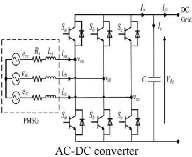
AC-DC converter
Fig. 2. PMSG connected to an ac/dc voltage source converter.
C. Rectifier modelling
PMSG streams isa, isb, isc what’s more, the dc yield voltage Vdc of the converter can be communicated as takes after:
Ls dis/dt= − Rs is + es–KSVdc (7) C dVdc/dt= iTs S –Idc (8)
Where
is=_ isaisbisc_T, es=_esaesbesc_T
S =Sa SbScT is the ac/dc converter switching functionswhich are defined as
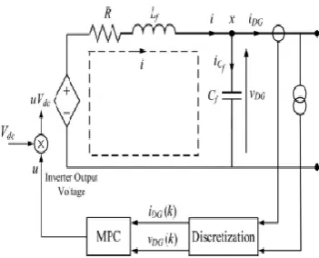
D. Inverter Modelling
The two 40 kW three-stage dc/air conditioning inverters which associate the dc lattice to the point of basic coupling (PCC) are indistinguishable, and the single-stage portrayal of the three-stage dc/air conditioning inverter is appeared in Fig. 3. To determine a state-space display for the inverter, Kirchhoff’s voltage and current laws are connected to circle I and point x separately, and the accompanying conditions are acquired:
Lfdi/dt+ iR+ vDG = uVdc (10) iDG = i–iCf (11)
where Vdc is the dc grid voltage, u is the control signal, R is the inverter loss, Lf and Cfare the inductance and capacitance of the low-pass (LPF) filter respectively, iDG is the inverter output current, iis the current flowing through Lf , iCfis the current flowing through Cf, and vDG is the inverter output voltage.
Fig. 3. Single-phase representation of the three-phase dc/ac inverter.
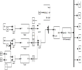
III. CONTROL MODELLING
B. Control modelling for the rectifier
Fig. 4. Configuration of the proposed fuzzy controller for the ac/dc
converter.
to be zero so that the PMSG just conveys genuine power. The present mistakes Δid and Δiq are at that point changed over into the abc edge and bolstered into a proportionalresonant (PR) controller to produce the required control signals utilizing beat width tweak.
C. Control modelling for the Inverter
Fig. 5. Configuration of the proposed fuzzy controller for the dc-ac
converter.
All together for the microgrid to work in both lattice associated what’s more, islanded methods of operation, a model-based controller utilizing MPC is proposed for the control of the inverters. MPC is a show based controller and receives a subsiding skyline approach in which the advancement calculation will figure an arrangement of control activities to limit the chose destinations for the entire control skyline, yet just execute the principal control activity for the inverter. At whenever step, the advancement procedure is rehashed in view of new estimations over a moved expectation skyline. Thusly, MPC can influence the yield to track the reference at the following stage, and additionally design and right its control motions along the control procedure. This will ensure a better transient reaction contrasted with customary PID/PR controllers [32], [33]. To infer the control calculation for the
inverters, the state-space conditions are changed into increased state-space conditions by characterizing the incremental factors in the accompanying configuration:
Δξ(k) = ξ(k) –ξ(k –1) (17)
IV. SIMULATION RESULTS AND ANALYSIS
The reenactment model of the proposed dc lattice based breeze control age framework appeared in Fig. 1 is actualized inMATLAB/Simulink. The viability of the proposed plan idea is assessed under various working conditions when the microgrid is working in the network associated or islanded method of operation. The framework parameters are given in Table I. The impedances of the conveyance line are acquired from [34]. In down to earth usage, the estimations of the converter and inverter misfortune protection are not unequivocally known. Thusly, these values have been coarsely evaluated.
The staying genuine and receptive power that is requested by the loads is provided by the network which is appeared in Fig. 7. It can be seen from Fig. 7 that the network conveys 40 kW of genuine power and 4 kVAr of receptive energy to the heaps for 0 ≤ t < 0.2 s. The add up to genuine and receptive power provided to the heaps is around 60 kW and 12 kVAr as appeared in the power waveforms of Fig. 8. The insecure estimations saw in the power waveforms for 0 ≤ t < 0.08 s are on the grounds that the controller requires a periodof around four cycles to track the power references amid the introduction time frame. When contrasted with customary control procedures, it can be watched that the proposed MPC calculation can rapidly track and settle to
Fig. 6. Real (upper) and reactive (lower) power delivered by inverter 1.
Fig:7. Real (upper) and reactive (lower) power delivered by inverter
2.
Fig:8. Real (upper) and reactive (lower) power delivered by the grid.
Fig:9. Real (upper) and reactive (lower) power consumed by the loads.
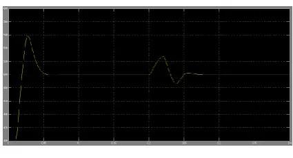
Fig. 10. DC grid voltage.
2 and the framework additionally cause a transient in the heap control.
D. Case 2: Connection of AC/DC
Converter During Grid-Connected Operation
The most significant advantage of the proposed dc grid based wind power generation system is that it facilitates the connection of any PMSGs to the micro grid without the need to synchronize their voltage and frequency. This capability is demonstrated inthis case study.
Fig. 11. Real (upper) and reactive (lower) power delivered by inverter 1.
Fig. 12. Real (upper) and reactive (lower) power delivered by inverter 2.
Fig. 13. Real (upper) and reactive (lower) power delivered by the grid.
Fig. 14. DC grid voltage.
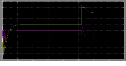
The microgrid works associated with the matrix and PMSG A is detached from the dc lattice for 0 ≤ t < 0.2 s as appeared in Fig. 1. The genuine power produced from each of the remaining three PMSGs is kept up at 5.5 kW and their collected genuine energy of 16.5 kW at the dc lattice is changed over by inverters 1 and 2 into 14 kW of genuine power and 8 kVAr of responsive power. As appeared in Figs. 11 and 12, every inverter conveys genuine and receptive energy of 7 kW and 4 kVAr to the heaps individually. Whatever is left of the genuine and responsive power request of the heaps is provided by the lattice as appeared in Fig. 13. It can be seen from Fig. 14 that the framework conveys 46 kWof genuine power and 4 kVAr of receptive power to the heaps.
the dc lattice voltage at t = 0.26 s as saw in Fig. 14 which is then reestablished back to its ostensible voltage of 500 V for 0.26 ≤ t < 0.4 s. The network additionally all the while diminishes its supply to 40 kW of genuine power for 0.26 ≤ t < 0.4 s while its responsive power stays consistent at 4 kVAr as appeared in Fig. 13.
E. case 3: Islanded Operation
At the point when the microgrid works islanded from the appropriation lattice, the aggregate age from the PMSGs will be inadequate to supply for all the heap request. Under this condition, the SB is required to dispatch the important energy to guarantee that the microgrid keeps on working steadily. The third case contemplate demonstrates the microgrid operation when it islands from the network.
Fig. 15. Real (upper) and reactive (lower) power delivered by the grid.
Fig. 16. Real (upper) and reactive (lower) power delivered by inverter 1.
Fig. 17. Real (upper) and reactive (lower) power delivered by inverter 2.
Fig. 18. Real power delivered by Storage battery
Fig. 19. DC grid voltage. .
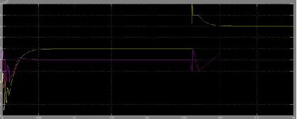
cycle, bringing about zero genuine and receptive control provided by the matrix for 0.2 ≤ t < 0.4 s.With the loss of control supply from the matrix, the power awkwardness between the age and load request is distinguished by the EMS. To keep up the solidness of the microgrid, the SB is entrusted by the EMS to supply real power of 40 kW at t = 0.26 s as shown in Fig. 18. At the same time, the real and reactive power delivered by each inverter is also increased by the EMS to 30 kW and 6 kVAras shown in Figs. 16 and 17 respectively. Fig. 19 shows the dc grid voltage where slight voltage fluctuations are observed at t = 0.26 s. The initial voltage rise at t = 0.26 s is due to the power supplied by the SB while the subsequent voltage dip is due to the increase in power drawn by the inverters.
V.CONCLUSION
To supply genuine energy of 40 kW at t = 0.26 s as appeared in Fig. 18. In the meantime, the genuine and responsive power conveyed by each inverter is likewise expanded by the EMS to 30 kW and 6 kVAras appeared in Figs. 16 and 117 separately. Fig. 19 demonstrates the dc framework voltage where slight voltage vacillations are seen at t = 0.26 s. The underlying voltage ascend at t = 0.26 s is expected to the control provided by the SB while the consequent voltage plunge is because of the expansion in control drawn by the inverters and unwavering quality to the operation of the microgrid. Be that as it may, the proposed control configuration still requires promote trial approval since estimation blunders because of errors of the voltage and current sensors, and demonstrating blunders because of varieties in genuine framework parameters, for example, appropriation line and transformer impedances will influence the execution of the controller in reasonable execution. Also, MPC depends on the exactness of model foundation, consequently additionally explore on enhancing the controller power to displaying incorrectness is required. The reenactment comes about
acquired and the examination performed in this paper fill in as a reason for the outline of a dc lattice based breeze control age framework in a microgrid.
REFERENCES
[1] M. Czarick and J.Worley, ―Wind turbines and tunnel fans,‖ Poultry Housing Tips, vol. 22, no. 7, pp. 1–2, Jun. 2010.
[2] The poultry guide: Environmentally control poultry farm ventilation systems for broiler, layer, breeders and top suppliers. [Online]. Available: http://thepoultryguide.com/poultry-ventilation/
[3] Livestock and climate change. [Online].
Available: http://www.
Worldwatch.org/files/pdf/Livestock%20and%2 0Climate%20Change.pdf.
[4] Farm Energy: Energy efficient fans for poultry production. [Online].Available: http://farmenergy.exnet.iastate.edu.
[5] A. Mogstad, M. Molinas, P. Olsen, and R. Nilsen, ―A power conversion system for offshore wind parks,‖ in Proc. 34th IEEE Ind. Electron., 2008, pp. 2106–2112.
[6] A. Mogstad and M. Molinas, ―Power collection and integration on the electric grid from offshore wind parks,‖ in Proc. Nordic Workshop Power Ind. Electron., 2008, pp. 1–8.
[7] D. Jovic, ―Offshore wind farm with a series multiterminal CSI HVDC,‖ Elect. Power Syst. Res., vol. 78, no. 4, pp. 747–755, Apr. 2008.
[9] T. Dragicevi, J. M. Guerrero, and J. C Vasquez, ―A distributed control strategy for coordination of an autonomous LVDC microgrid based on power-line 1755ignalling,‖ IEEE Trans. Ind. Electron., vol. 61, no. 7, pp. 3313–3326, Jul. 2014.