A Novel Miniaturization Double Folded Quarter Mode Substrate
Integrated Waveguide Filter Design in LTCC
Jian Zhou, Yong-Zhong Zhu*, and Zihao Liu
Abstract—A novel double-folded quarter mode substrate integrated waveguide (DFQMSIW) filter is designed in low temperature co-fired ceramic (LTCC). This filter consists of multi-layer substrate integrated waveguide. More than 93.75% of the filter’s area is effectively decreased compared with original substrate integrated waveguide (SIW) filter for the technologies of Half-Mode and Folded are applied. Meanwhile, the dimensions are further reduced because of the technologies of LTCC and the vertical dimensional cavities configuration. The fabricated insertion loss and return loss are 1.9 dB and 13.5 dB, respectively.
1. INTRODUCTION
As we know, substrate integrated waveguide (SIW) is a novel waveguide construction which is smaller than metallic waveguide and losses less than micro-strip line. But the SIW still has a biggish plane dimension [1]. Hong et al. proposed the concept of Half-Mode in 2006 [2], and then Quarter-Mode and Eighth-Mode are presented one after the other. The sizes of Half Mode Substrate Integrated Waveguide (HMSIW), Quarter Mode Substrate Integrated Waveguide (QMSIW) and Eighth Mode Substrate Integrated Waveguide (EMSIW) have been decreased by about 50%, 75% and 87.5% compared with the equivalent SIW cavities, respectively [3–7]. On the other hand, folded SIW (FSIW), a multilayer circuit process with three-dimensional integration features, was proposed by Grigoropoulos et al. in 2005 [8] and particularly analyzed by Che et al. in 2008 [9], considered the best method for the miniaturization of SIW filters [10]. Double-folded SIW (DFSIW) and quadruple-folded SIW (QFSIW) are proposed soon afterwards, and the QFSIW can even reduce about 89% of the circuit area of a conventional SIW cavity [11, 12]. Nowadays, low temperature co-fired ceramic (LTCC) technology has been exploited to minimize microwave components for its three-dimension integration which can reduce the package area notably [13–15]. In [14], a compact LTCC filter was introduced, which reduced about 60% of the conventional PCB microstrip filter’s area
For further reducing the size of filter, a double-folded quarter mode substrate integrated waveguide (DFQMSIW) resonator is adopted, and a novel two-order DFQMSIW filter is designed in this paper. The resonator works at TE101 mode, and center frequency of the filter is 1.51 GHz. The insertion loss
of the fabricated filter is 1.9 dB, and the return loss is below −13 dB. The area of the filter is reduced more than 93.75% compared with original SIW filter
2. DFQMSIW RESONATOR DISCUSSION
In order to design a multilayer DFQMSIW filter, the DFQMSIW resonator should be discussed at first. Based on QMSIW resonator, QFDMSIW is folded twice, which is why the DFQMSIW resonator has
Received 14 April 2016, Accepted 18 May 2016, Scheduled 3 June 2016
* Corresponding author: Yong-Zhong Zhu ([email protected]).
two substrate layers with an L-shaped slot in the middle metallic layer. The structure of DFQMSIW resonator is shown in Figs. 1(a) and 1(b), respectively. The substrates used to design the resonator, whose dielectric constant is 5.9 and loss tangent 0.0015, are obtained by LTCC Frro-A6 technology, and the thickness of each substrate layer is 0.096 mm. A spill micro-strip line is utilized for feeding. The dimension of DFQMSIW resonator can be calculated based on the following formula [15–17]:
WeffDF QMSIW = W SIW
eff
4 + ΔW (1)
The resonant frequency of the mode of the rectangular DFQMSIW resonator is given by the following formula [15–17]:
fDF QMSIW
mop = 2π√1με
mπ
4LDF QMSIWeff
2
+
pπ 4WeffDF QMSIW
2
(2)
where m = p = 1, 2, 3. . . , and μ and ε are the permeability and permittivity of the substrate, respectively. LDF QMSIWeff and WeffDF QMSIW are the equivalent length and width, respectively. ΔW is the added width and observed owing to variations in the feeding position, and the magnetic walls are not ideal due to fringing fields.
Figure 2(a) shows the electric field magnitude within the cavity. Obviously, the closer the L-shaped slot is located, the stronger the electric filed intensity is. Meanwhile, the closer the feeding line
(a) (b)
Figure 1. (a) The structure of DFQMSIW resonator; (b) Top view of DFQMSIW resonator.
(a) (b)
is located, the stronger the electric filed intensity is, and conversely it is weaker. Fig. 2(b) shows the frequency response of the DFQMSIW resonator. The center frequency is 1.49 GHz. The insertion loss is 0.1 dB, and the return loss is below−32 dB. The parameters of the top metallic layer are given below: Z1 = 12.5 mm, Z2 = 1.4 mm, Z3 = 2 mm, Z4 = 2 mm. The results of Fig. 2 are obtained through Ansoft HFSS 14.
3. MINIATURIZATION DFQMSIW FILTER DESIGN
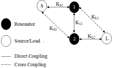
To effectively reduce the area of the DFQMSIW filter, a novel vertical dimensional cavities configuration is proposed as Fig. 3 and Fig. 4. In Fig. 3, a schematic coupling topology of the proposed bandpass filter is given. As shown in Fig. 3, input (S) and output (L) are coupled to both resonators, and there is a direct coupling, denoted by K12, between adjacent resonators. The scheme of coupling causes
a transmission zero to occur at the upper band. The direct coupling is realized through the slot or coupling window in the ground—the metallic layer between the adjacent DFQMSIW resonators 1 and 2.
Figure 3. Coupling scheme of the proposed two-cavity filter.
The target of the fabricated filter is to make the center frequency operate at 1.5 GHz as the relative bandwidth is realized to 4%, and to make the return loss reach −20 dB. Meanwhile, the insertion loss is more than −1 dB. The coupling matrix and external quality factor are found to be:
⎡ ⎢ ⎣
0 0.92 0.064 0 0.92 0 0.9 0.05 0.064 0.9 0 0.92 0 0.05 0.92 0
⎤ ⎥ ⎦
QS1 =QL2= 18.17.
The coupling coefficient KS1 = 0.92 means that the coupling between input (S) and resonator 1
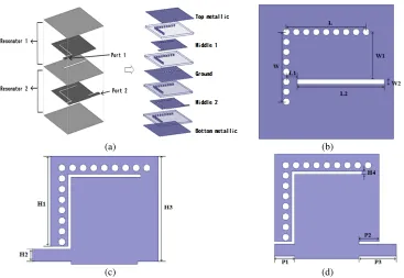
is strong for there is a direct coupling achieved through microstrip line, and so as to output (L) and resonator 2. The coupling between resonators 1 and 2 is strong too, because there is also a direct coupling through a rectangle slot in the ground. But the coupling between input (S) and resonator 2 is a cross coupling, so the coupling is weak. Similarly, the coupling between output (L) and resonator 1 is weak. In Fig. 4(a), there are two resonator cavities in the filter, and two substrates are between each two metallic layers. Because of the LTCC technology, the thickness of each substrate layer is only 0.096 mm, and the thickness of the filter which consists of eight substrate layers is only 0.768 mm. The radius of all vias is 0.1 mm, and the space of adjacent vias is 0.3 mm. In order to measure the performance indicators expediently, the feeder lines and ground are guided to the upper surface of the top substrate by vias as shown in Fig. 5. The dimensions of the proposed filter’s ground are given below: W = 8.4 mm, L= 8.4mm, L1 = 1.3 mm, L2 = 10.5 mm, W1 = 5.7 mm,W2 = 0.6 mm,H1 = 10.2 mm,H2 = 1.4 mm, H3 = 12.1 mm, H4 = 0.5 mm, P1 = 2.35 mm, P2 = 4.35 mm, P3 = 2.35 mm. The dimension of the whole filter is 16.2 mm×16.2 mm×0.768 mm.
(a) (b)
(c) (d)
Figure 4. The structure of the DFQMSIW filter: (a) The topology structure of the DFQMSIW filter cavities; (b) The top view of Ground;(c) The top view of Middle 1; (d) The top view of Middle 2.
Figure 5. The whole view of the DFQMSIW filter.
Figure 6. The picture of the two-order DFQMSIW filter.
Fig. 7, the filter works at 1.51 GHz. The insertion loss and return loss are 1.9 dB and below −13 dB, respectively. The relative bandwidth is about 4%. All measured data are obtained by Agilent N5230A Vector Network Analyzer which is corrected before measuring, and all simulated data are obtained through Ansoft HFSS 14.
Figure 7. The simulated and measured results of the two-order DFQMSIW filter.
be because the measuring environment is not well controlled, and the SMA connectors also introduce some loss. On the other hand, although the accurate model of the way that the feeder lines and ground are guided to the upper surface of the top substrate by vias is included in the simulations, it can also bring a deviation because of fabrication error. Based on the results, the simulation and measurement are in good agreement.
4. CONCLUSION
A novel two-order DFQMSIW filter is designed in LTCC, and the filter shows a good performance. By using a vertical configuration in three-dimensional space and the technologies of Folded Half-Mode, not only the miniaturization of two-order filter is realized, but also the reduction of area is even up to 93.75% compared with the conventional SIW cavity. At the center frequency of 1.51 GHz, the designed filter achieves a relative bandwidth up to 4% and a high selectivity. Plus, a transmission zero is created to improve upper-stopband performance. The volume of the filter is 16.2×16.2×0.768 mm. The filter has a compact size and simple structure, which makes it competitive for application in microwave communication systems.
ACKNOWLEDGMENT
This work was supported by the National Natural Science Foundation of China (No. 61302051), Natural Science Foundation of Shaanxi Province of China (NO. 2012JQ8026), the Basic Research Program of ENGG University of the Program of ENGG University.
REFERENCES
1. Deslandes, D. and K. Wu, “Integrated microstrip and rectangular waveguide in planar form,”IEEE
Microwave and Wireless Components Letters, Vol. 11, No.2, 68–70, 2001.
2. Hong, W., B. Liu, Y. Q. Wang, Q. H. Lai, and K. Wu. “Half mode substrate integrated waveguide: A new guided wave structure for microwave and millimeter wave application,” (Keynote Talk)Joint
31st Int. Conf. on Infrared and Millimeter Waves and 14th Int. Conf. on Terahertz Electronics,
Shanghai, September 18–22, 2006.
3. Chen, Y. J., W. Hong, and K. Wu, “Half mode substrate integrated waveguide (HMSIW) directional filter,” IEEE Microwave and Wireless Components Letters, Vol. 17, No. 7, 504–506, 2007.
4. Wu, L.-S., X.-L. Zhou, W.-Y. Yin, C.-T. Liu, L. Zhou, J.-F. Mao, and H.-L. Peng, “A new type of periodically loaded half-mode substrate integrated waveguide and its applications,” IEEE Trans.
5. Memon, M. U. and S. Lim, “Frequency-tunable compact antenna using quarter-mode substrate integrated waveguide,”IEEE Antennas &Wireless Propagation Letters, Vol. 14, No. 3, 1606–1609, 2015.
6. Cao, H., S. He, H. Li, and S. Yang, “A compact wideband bandpass filter using novel csrr loaded qmsiw resonator with high selectivity,”Progress In Electromagnetics Research C, Vol. 41, 239–254, 2013.
7. Zhu, Y., “A source-load coupled bandpass filter using one-eighth mode substrated waveguide cavity,” 31th URSI General Assembly and Scientific Symposium, 1–4, 2014.
8. Grigoropoulos, N., B. S. Izquierdo, and P. R. Young, “Substrate integrated folded waveguides (SIFW) and filters,” IEEE Microw. Wirel. Compon. Lett., Vol. 15, No. 12, 829–831, 2005.
9. Che, W., L. Geng, K. Deng, and Y. L. Chow, “Analysis and experiments of compact folded substrate-integrated waveguide,” IEEE Trans. Microwave Theory Tech., Vol. 56, No. 1, 88–93, 2008.
10. Chen, X.-P. and K. Wu, “Substrate integrated filters: Design techniques and structure innovations,”
IEEE Microwave Magazine, Vol. 15, No. 6, 121-133, 2014.
11. Wu, L.-S., X.-L. Zhou, and W.-Y. Yin, “A novel multilayer partialH-plane filter implemented with folded substrate integrated waveguide,” IEEE Microwave Wireless Compon. Lett., Vol. 19, No. 8, 494–496, 2009.
12. Yang, G., W. Liu, and F. Liu, “Two new electric coupling structures for double folded substrate integrated waveguide cavity filters with transmission zeros,” Microwave and Optical Technology
Letters, Vol. 55, No. 8, 1815–1818, 2013.
13. Shen, G. W., W.-Y. Yin, X.-W. Sun, and Q.-F. Wei, “A novel LTCC multilayer SIW linear phase filter,” Microwave Opt. Technol. Lett., Vol. 51, No. 10, 2357–2360, 2009.
14. Tsai, W.-L., T.-M. Shen, B.-J. Chen, T.-Y. Huang, and R.-B. Wu, “Triband filter design using laminated waveguide cavity in LTCC,” IEEE Trans. Compon. Package. Manuf. Tech., Vol. 4, No. 6, 957–965, 2014.
15. Huang, T. Y., T. M. Shen, and R. B. Wu, “A miniaturized bandpass filter using quadruple folded laminated waveguide cavity resonators in LTCC,”IEEE Asia-Pacific Microwave Conference
Proceeding (APMC), 99–102, 2010.
16. Jin, C., R. Li, A. Alphones, et al., “Quarter-mode substrate integrated waveguide and its application to antennas design,” IEEE Transaction on Antennas and Propagation, Vol. 61, No. 6, 2921–2928, 2013.