Implementation of Multilevel Inverter with
reduce power electronics Components for
Renewable Energy Source Application
Arvaplli Rajesh
M-tech Student Scholar Department of Electrical & Electronics Engineering, Sri Chundi Ranganayakulu
Engineering College, Guntur(Dt); A.P, India.
[email protected]
Y.Umaravisankar
Assistant Professor Department of Electrical & Electronics Engineering, Sri Chundi Ranganayakulu
Engineering College, Guntur(Dt); A.P, India.
[email protected].
N. hanuma naik
Head of The Department Department of Electrical & Electronics Engineering, Sri Chundi
Ranganayakulu Engineering College, Ganapavaram; Guntur (Dt); A.P, India
.
Abstract—in this paper family of multilevel inverter topology with reduced number of power switches is presented. The proposed inverter can generate both even and odd level. The proposed topology is suitable for symmetric structure. The proposed symmetric inverter results in reduction of power switches, power diode and gate driver circuits and also it may further minimize the installation area and cost. To prove the superiority of proposed topology is compared with conventional topologies. The implemented hybrid energy system is used to generate and distribute power among the remote areas as the solar energy and wind energy are plenty in nature. Depending on the availability of the solar and wind energy, this system feeds the loads in standalone mode or hybrid mode. The proposed concept is implemented to 7 level, 11 level multilevel inverter MATLAB/Simulink software is used for themodeling and simulation of the hybrid energy system.
Keywords— Hybrid System; Solar energy system; wind energysystem; Remote areas; modified inverter
I.INTRODUCTION
In recent era, the multilevel inverter is state of art power conversion system for high voltage and high power quality applications. The two-level inverter
with existing semiconductor technology may not suit for high voltage application which may increase the high voltage stress on switch, high Electro Magnetic Interference (EMI) and poor power quality output [1], [2]. In order to solve these issues the conventional multilevel inverters are introduced, but it may require high number of power semiconductor devices. So, the researchers are developing new multilevel inverter topologies with existing semiconductor technology to meet require high power quality with reduced power semiconductor devices [3].
Because of these advantages multilevel converters are more attractive in high power applications. However, the important benchmark for designing multilevel inverters is listed below.
• Low voltage stress on switches
• Low Electromagnetic interference.
• Low Harmonic Distortion
• Absence of LC Filter
• More redundant state
• Reliability
• Low Cost
The conventional multilevel inverter topologies are (i) Neutral Point Clamped (NPC) (ii) Flying Capacitor (FC) and (iii) Cascaded H-Bridge (CHB). These converters provide better output quality by increasing smaller voltage level; they are applied for commercial applications and industrial applications like AC Drives and FACTS Devices [4].
Theoretically, these topologies are capable of generating infinite number of equal stepped voltage level. Whereas, practically, the number of level increases as it requires more number of power switches, clamping diode, flying capacitor and associated components respectively. Furthermore, this may increase the installation area, cost of the converter and complex control circuits. In last few decades several authors were finding solution by introducing novel multilevel inverter topologies with reduction of power switches [5]-[8]. In symmetrical method all the dc sources voltage have unique value and it ensures good modularity.
In this work cost effective and reliable hybrid renewable energy system for the remote areas has been implemented and it uses solar energy system consists of PV array, boost converter with MPPT control and wind energy system having wind turbine, PMSG and uncontrolled rectifier, and modified Inverter based H-bridge which are discussed in the following sections.
In single-phase multilevel inverters, the most widely used techniques are cascaded H-bridge (CHB), diode-clamped and capacitor diode-clamped types [9]. In addition, many other techniques also exist. In particular, among these techniques, CHB single phase inverters have drawn attention because of their modularized circuit layout and simplicity. A variety of modulation techniques can be applied to CHB inverters. By increasing the number of cascaded H-bridges, the number of levels in CHB inverters increases [10].
Generally if the number of output voltage levels is increased, then the number of power electronic
devices and the number of isolated DC sources is also increased. This makes a CHB inverter further complex. In this paper, a novel multilevel inverter with minimum number of power electronic switching devices is proposed which is a modified version of
the multilevel inverter using series/parallel
conversion of DC sources. In the proposed Multilevel Inverter three similar Cascaded H-Bridges are used, each Bridge carries an auxiliary switch which will be Bi-directional in nature. However, three isolated dc sources are needed to generate the same number of output levels as compared to the conventional Cascaded H-Bridge Inverters. The number of switching devices used and the harmonics of the output voltage waveform for the proposed inverter are reduced as well [11-12].
II HYBRID RENEWABLE ENERGY SYSTEM FOR RURAL AREAS
Fig.1. Block diagram of Implemented Hybrid System with Modified converter Topology.
A. Solar Energy system
The basic blocks of the solar energy system are shown in the hybrid system Fig.1. It consists of PV array, DC-DC boost converter stage, and modified DC-AC converter stage with minimum power electronic switches followed by load. The load may be dc or ac load. For the dc load, PV is connected to the load through dc-dc boost converter where as in case of ac load, connected through DC-DC-AC power conversion stage. The Photo Voltaic (PV) cell converts the radiation or heat from the sun into electrical energy. Solar cell has non-linear relation between the output current and output voltage as given in (1) and output power changes with temperature and irradiation.
(1)
Fig.2 shows the most commonly used single-diode equivalent circuit model of PV cell and it is parallel combination of the current source, diode and a shunt resistance; the value of the shunt resistance is of very
high order. Resistance Rse is connected in series and is of small value. Where, Iph is photocurrent, ID is diode current, Io is reverse saturation current, A is ideality factor, q is charge of electron, K is Boltzmann’s constant, T is cell temperature, RSe is series resistance, RSh is shunt resistance, I is cell current, V is cell voltage.
As the conversion efficiency of PV cell is low, we have to use more PV modules in series or parallel to obtain the required voltage or current and the output dc voltage can be increased by using suitable power converter such as dc-dc boost converter (IGBT is used as switching device).The output of the boost converter can be directly given to the DC loads, for AC loads a DC-AC inverter is placed in between the load and the boost converter, the detailed description about the DCAC inverted is discussed.
Fig.2. PV (Solar cell) modeling
B. Wind Energy Systems
The advanced wind turbine designs and tremendous research developments in the field of power electronics made Wind energy as one of the best alternative source for power generation. And it features like clean, variable, environment friendly, huge availability makes as promising one. Wind energy system (WES) Fig.1 consists of the wind turbine, permanent magnet synchronous generator (PMSG), diode bridge rectifier, the modified inverter followed by load. As mentioned in the above solar energy system; here also we can connect the DC load directly to the rectifier/dc-dc converter output, AC load is connected at the inverter output. With help of aerodynamically designed blades, the wind turbine captures power from the wind and converts kinetic energy into rotating mechanical energy that can be used to drive a PMSG. The power in (watts) captured by the wind turbine is given by
(2)
The mechanical torque in (N-m) is given by
(3)
Where, A is the wind turbine rotor swept area in (m2),
VW is the speed of the wind in (m/s), WM is the
mechanical speed of the wind turbine in (rad/s), CP is
the turbine power coefficient and ρ is the air density in kg/m3. Wind turbine may be fixed or variable speed type and its model selection depends on various factors like variation of wind, location and climate conditions. Good modeling, design and control provide the best possible results. A permanent magnet synchronous generator with a variable speed turbine provides maximum power with operating speed range. In this paper a multi-pole direct drive PMSG is used for the implementation and it is slow speed machine which has advantages like less weight, minimum losses, low cost and less maintenance because of no gearbox. This feature makes the implemented system highly reliable, efficient and cost-effective. The wind energy system design leads to more simple because of selection of PMSG as
generator. As the output voltage and frequency changes with generator speed, we have to use power electronic converter as a interface to feed the ac loads. Like in solar, here also we can use DC-DC converter with popular MPPT P&O technique to get continuously maximum power and can produce controlled dc output to feed dc loads directly.
The rectifier converts generator ac output to zero frequency dc components. The ripples in the rectifier output can be minimized by using capacitor filter. The dc link voltage that can be given to de loads or dc-ac inverter can be calculated as
(4)
Where, Vrms is the input ac line voltage and Vo is the output dc voltage. The dc-ac inverter is explained in the next section. Both the solar energy system and wind energy system can be used separately to connect to either AC or DC load, even the combined hybrid system can supply power to the load, so the system can be used individually if one of the system failed to deliver the electricity, the reliability of the system won’t be effected further by using these renewable systems, the life span is around 25 years and guarantee is given to the system
III MODIFIED DC-AC INVERTER
Fig.3. A single phase seven-level Modified Inverter
Implementing with a modified inverter topology that uses only six switches. The system consists of a capacitor voltage divider, an H bridge and also a two bidirectional switches. The system consists of a capacitor voltage divider, an H bridge and also a bidirectional switches. Switches are IGBTs with diode’s. The triggering pulses for the six switches are generated by comparing three reference waves with the carrier wave. The reference signals and the carrier will have same magnitude and the frequency but each reference is shifted by value equal to carrier magnitude. The reference voltages are compared the carrier wave and firing pulses for the 6 switches are generated. The single H-bridge provides 3 level output. Remaining 4 levels (+V/3, +2V/3 and V/3, -2V/3) are obtained by triggering S2 with S5&S6, S3 with S5&S6.The modified topology used for both standalone and hybrid systems that leads in low cost and less complexity.
IV.ELEVEN LEVEL INVERTER
In hybrid power system and stand alone renewable energy systems, power electronics technology plays a vital role in the interfacing wind/solar output to loads in remote areas. Good quality of output, minimum stress on switches, and maximum efficiency in medium and high power applications can be obtained by using multi-level inverters. The implemented system uses the modified DC-AC inverter topology shown in Fig.4 to generate eleven level output voltage. In general, to generate a eleven level output waveform we require minimum of eleven in case of H-bridges with unequal dc sources and sixteen
switches H-bridges with equal dc sources,
considering the cost and reliability.
Fig.4. A single phase eleven-level Modified Inverter
Implementing with a modified inverter topology that uses only eight switches. The system consists of a capacitor voltage divider, an H bridge and also a four bidirectional switches. The system consists of a capacitor voltage divider, an H bridge and also a bidirectional switches. Switches are IGBTs with diode’s. The triggering pulses for the six switches are generated by comparing three reference waves with the carrier wave. The reference signals and the carrier will have same magnitude and the frequency but each reference is shifted by value equal to carrier magnitude. The reference voltages are compared the carrier wave and firing pulses for the 6 switches are generated. The single H-bridge provides 3 level output.
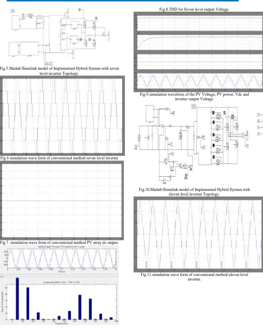
Fig.5.Matlab/Simulink model of Implemented Hybrid System with seven level inverter Topology.
Fig 6 simulation wave form of conventional method seven level inverter
Fig.7. simulation wave form of conventional method PV array dc output.
Fig.8.THD for Seven level output Voltage.
Fig.9.simulation waveform of the PV Voltage, PV power, Vdc and inverter output Voltage.
Fig.10.Matlab/Simulink model of Implemented Hybrid System with eleven level inverter Topology.
Fig.12.simulation waveform of the PV Voltage, PV power, Vdc and inverter output Voltage.
Fig.13.THD for Seven level output Voltage.
VI.CONCLUSION
This paper has presents a novel single phase cascaded H-bridge Inverter with reduced number of power electronics devices and isolated DC sources. Simulations are carried out in MATLAB/Simulink. A Generalized switching algorithm which can be used for any number of levels is presented. The performance of the suggested novel cascaded H-Bridge multilevel inverter is investigated in detail. The modulation waveform and the harmonic analysis are also presented for various values of modulation strategies. By properly adjusting the modulation index, the required number of levels of the inverter output voltage can be achieved. The modular structure of wind turbine-PMSG, Maximum Power Point Tracking control in dc-dc boost converter, simplified dc-ac inverter with modified that generates seven level good quality of output with minimum power electronic switches, minimum THD and supplying both dc as well as ac loads makes the
implemented system more reliable and cost effective in remote areas electrification.
REFERENCES
[1] IEA, “World Energy outlook report,” IEA, 2011.
[2] Chen Jian, CheYanbo and Zhao Lihua, “Design and Research of Off grid Wind-Solar Hybrid Power
Generation Systems,” in Proc. of 4th
International Conference on Power Electronics Systems and Applications (PESA), pp. 1-5, Hong Kong, China, June 8-10, 2011.
[3] Recayi pecen and Ahmet Nayir “Design and Implementation of a 12 kW Wind- Solar Distributed Power and Instrumentation System as an Educational Testbed for Electrical Engineering Technology Students” Modern electrical power system 2010, Wroclaw, Poland
[4] A.M. Jain and Dr. B.E. Kushare “Techno- Economics of solar wind hybrid energy system in Indian context: A case study” Tamilnadu,pp 39 – 44, 2007.
[5] Roberto Faranda and Sonia Leva “ Energy comparision Techniques for PV system” WSEAS transactions in power system; vol.2, 2008.
[6] BalasubramanianIndu Rani, Ganesan Saravana Ilango and Chilakapati Nagamani “Control Strategy for power flow management in a PV system supplying DC Loads” IEEE Transactions on industrial electronics; vol.6, 2013.
[7] T. Esram and P.L. Chapman, “Comparison of photovoltaic array maximum power point tracking
techniques,” IEEE Transactions on Energy
Conversion, vol. 22, no. 2, 2007, pp. 439-449.
[8] Teena Jacob and Arun S “ Maximum Power Point Tracking of Hybrid PV and wind energy systems using a New Converter Topology,”ICGT, pp 280 – 287, 2012.
[10] M. H. Nehrir, C. Wang, K. Strunz, H. Aki, R. Ramakumar, J. Bing, Z. Miao, and Z. Salameh, “A review of hybrid renewable/alternative energy
systems for electric power generation:
Configurations, control, and applications,” IEEE Trans. Sustain. Energy, vol. 2, no. 4, pp. 392–403, Oct. 2011.
[11] M. G. Villalva, E. Ruppert F. and J.R. Gazoli, “Analysis and simulation of the P&O MPPT algorithm using a linearized FV array model,” Industrial Electronics, 2009. IECON '09. 35th Annual Conference of IEEE, 2009, pp. 231-236.
[12] C. N. Bhende, S. Mishra, and S. G. Malla, “Permanent magnet synchronous generator based standalone wind energy supply system,” IEEE Trans.Sustain. Energy, vol. 2, no. 4, pp. 361–373, Oct. 2011.
Author’s Profile:
Arvapalli Rajesh was born in the year 1992.He obtained B.Tech degree in Electrical and
Electronics Engineering from
srichundiranganayakulu engineering college Presently he is pursuing M.Tech (PE) in Sri chundiranganayakulu engineering college.
Y.Uma Ravi Sankar was born in the year 1983. He obtained B.Tech degree in Electrical and Electronics Engineering from Vignan’s Engineering college,vadlamudi. He has Completed
M.Tech(EPE) JNTU college of
Engineering,Hyderabad. Presently he is working as an Asst. professor in Sri Chundi Ranganayakulu Enggcollege.Chilakaluripet.