Available online: https://edupediapublications.org/journals/index.php/IJR/ P a g e | 1195
Optimization of Wick Shape in a Heat Pipe for High Heat Transfer
P. Rakesh Kumar& M.Lava Kumar1PG Student, Department of Mechanical Engineering, G.Pulla Reddy Engineering College
Kurnool, Andhra Pradesh , India
2Assistant professor, Department of Mechanical Engineering ,G.Pulla Reddy Engineering
College, Kurnool , Andhra Pradesh , India
[email protected] & [email protected] Abstract
Heat pipe is a device and it has high ability
to dissipate the heat. In modern days
electronic systems generate more heat in the
electronic components, to remove that heat
from the electronic devices we use heat pipe.
Heat pipe plays very important role in
cooling of the electronic systems like
computers, laptops, cell phones, T.V
Circuits, transformers. In this work inside of
the heat pipe the wick structure is modified.
The copper fins are fitted to the wick
structure in the inside of the heat pipe. The
length of the heat pipe is divided into the
three sections evaporator section, adiabatic
section and condenser section. The heater is
fitted in the evaporator section and power is
supplying to the heater. The thermocouple
wires are attached in the different sections
of the heat pipe.Working fluids are used in
this work is water and nano fluid (Al2O3).
First we use working fluid as water and we
take temperature readings at different
sections after that we use nano fluid as
working fluid and we take temperature
readings at different sections. After
completion of taking the temperature
readings, we calculate the heat transfer
rates for both working fluids for water and
nano fluid. And then comparison of the heat
transfer rates of the working fluids water
and nanofluid. By using the nano fluid as
working fluid in the heat pipe the heat
transfer rates are increased.
Key Words: Heat Pipe, Water, Nano fluid,
Thermocouple wires and Heat Transfer Rate
I. Introduction
Now a days modern electric component
generates high heat in the electronic
devices. So this generation of high heat
from the electronic components causes
the damage of the electronic devices. So
to prevent this damage and dissipate
more heat from the electronic devices we
Available online: https://edupediapublications.org/journals/index.php/IJR/ P a g e | 1196
it has more ability to dissipate the heat
and removes the heat from the electronic
devices. Heat pipe is a very important
device to transfer the large quantities of
heat through a small area with small
temperature difference.Heat pipes are
very frequently used in the space
applications. The main characteristic of
heat pipe is, heat pipe works in the
absence of gravity also and liquid flow
does not depend on gravity. Heat pipe
has ability of accepting the heat in
non-uniformly manner. Heat pipe is a very
simple mechanical device and it has no
moving parts. Heat pipe is a simple
device it makes the change of phase heat
transfer. Heat pipe works in the absence
of gravity of also. The heat pipe is very
much useful in branches of Electronics,
Air-conditioning systems, I.C Engines,
Gas turbines and Building industries.
Heat pipe is an ideal device for
removing heat from either a
concentrated heat source or from a low
temperature heat source. This is the
salient feature of heat pipe and this
feature is very much useful in the space
applications. Heat pipe has a circular
cross section and it has a layer of
wicking material covered at the inner
surface of the heat pipe. Heat pipe is
very simple in construction. Heat pipe is
a two phase heat transfer device.
Transports heat from a heat source to the
heat sink. Effective heat transfer takes
place in the heat pipe. There is no
external pumping power in the heat pipe.
It is a self regulating device. There is no
vibration and noise in the operating of
the heat pipe. The important features of
the heat pipe are good reliability and it
has capacity to work in weightless
condition in the space and it also works
in the under isothermal conditions
without need of the any external power
input device. This heat pipe is very good
for environment, because there is no
pollution caused by the heat pipe. The
main important features of the heat pipe
are it has no moving parts, it requires no
external energy source to start, reversible
in operation, completely silent, high
reliability. There are no corrosive
materials inside of the heat pipe.
The different types of working fluids can be
used in the heat pipe. The working fluid and
wick structures are located inside of the heat
pipe. There is no mechanical and chemical
degradation in the heat pipe. Gravity does
Available online: https://edupediapublications.org/journals/index.php/IJR/ P a g e | 1197
pipes are very frequently used in the space
applications, cooling of computers, mobiles,
laptops and cooling of solar collectors. This
heat pipe works based on the conduction and
convection process. Heat pipe is a passive
device and it transport heat from evaporator
to the condenser. A heat pipe contains three
sections heating section (evaporator
section), adiabatic section, cooling section
(condenser section). The main parts of the
heat pipe are enclosed container, wick
material and working fluid.
II. WORKING PRINCIPLE OF HEAT PIPE
Figure 1 Working Principle of Heat Pipe
The device it makes the change of phase
heat transfer is called the heat pipe. Heat
pipe is a highly passive device for the
transport the heat from the evaporator to
condenser. Very large quantities of heat can
transport from the heat source to heat sink
with minimum temperature drop. The heat
pipe is in the circular shape. This circular
heat pipe contains the layer of wick material
at the inner side of heat pipe. The main
components of the heat pipe are enclosed
container, wick structure and working fluid.
A heat pipe contains three sections heating
section (evaporator section), adiabatic
section, cooling section (condenser section).
The heat pipe is in the circular shape. This
Available online: https://edupediapublications.org/journals/index.php/IJR/ P a g e | 1198
material at the inner side of heat pipe. The
main components of the heat pipe are
enclosed container, wick structure and
working fluid. The liquid means working
fluid is placed in the inside of the heat pipe.
When heat is added in the evaporator section
the liquid gets heat and this liquid converts
into vapor. This vapor moves in the wick
material and it enters into the adiabatic
section. In the adiabatic section, there is no
heat loss occur because the heat pipe is
insulated with insulated rope in this
adiabatic section. And then this vapor is
enters into the cooling section. In this
section the vapor converts into the liquid by
the condenser. After that this liquid came
back into the evaporator section and then
again liquid gets heat and it converts into the
vapor and again this vapor travels into the
condenser section and converts into the
liquid. This cyclic process occurs in the heat
pipe.
Heat pipe has a most advantage that
one is heat pipe works in the absence of
gravity. The absence of gravity does not
affect the operation of heat pipe. Liquid flow
does not depend on the gravity. Heat pipe
does not require any external energy for
operating and it is reversible in operation.
Heat pipe is very good reliable device for
high heat dissipations. No noise produces in
the heat pipe operation so heat pipe is the
environmental friendly device.
III. EXPERIMENTAL WORK
Available online: https://edupediapublications.org/journals/index.php/IJR/ P a g e | 1199
The above figure shows the experimental
setup of the heat pipe. In this experiment
first of all we take one copper pipe. The heat
pipe is made with copper pipe. The length of
the heat pipe is the 50cm. The inside of this
heat pipe the wick structure is modified; the
four fins are fitted to the wick structure in
the inside of the heat pipe. Fins increase the
rate of heat transfer. The length of the heat
pipe is 50cm. The length of the heat pipe is
divided into three sections. The heat pipe is
divided into the evaporator section, adiabatic
section and condenser section. In the above
figure evaporator section is fitted with the
heater, this heater gets heat from the
autotransformer. From the autotransformer
two connection wires are attached to
voltmeter (V) and ammeter (I).
Autotransformer gives power supply to the
voltmeter and ammeter. On upper side of the
autotransformer there is rotating plate type
device is located, if we rotate this plate on
the autotransformer the indicators on the
voltmeter and ammeter changes.
The indicator on the ammeter changes form
0.1 Amperes to 0.2 Amperes,
simultaneously indicator on the voltmeter
changes from 70V to 80V. So the current (I)
comes from the ammeter and voltage (V)
comes from the voltmeter by adjusting the
autotransformer. The power supply comes
from the both current and voltage. The
power (P) =Voltage (V) X Current (I), so
from the autotransformer one wire is
connected to the voltmeter and other wire is
connected to the ammeter. The heater is
fitted to the heat pipe in the evaporator
section. The wires from the ammeter and
voltmeter are connected to the heater. So the
power is supplying to the heater. In this
work we use two working fluids. The
working fluids used in this experiment are
water and nanofluid (Al2O3). Inside of this
heat pipe first we take water as working
fluid. The working fluid water gets heated in
the evaporator section and then it converts
into the vapor. This vapor moves to the
adiabatic section. In the adia batic section
there is no heat loss occur, because insulated
rope is winded in the adiabatic section. And
then this vapor moves to the condenser
section. In the condenser section the steel
pipe is fitted externally to the heat pipe.
Water is supplying externally to the steel
pipe from the small bucket. Small bucket is
filled with water, from this bucket one pipe
is attached to the steel pipe. Through pipe
Available online: https://edupediapublications.org/journals/index.php/IJR/ P a g e | 1200
continuously. This steel pipe is fitted to the
heat pipe because for the heat dissipation.
The vapors in the condenser section are
cooled by the external supplying of water
through the steel pipe. So the vapor gets
cooled and converts into the liquid. This
liquid is collected from the heat pipe
through the water container. The
thermocouple wires are attached to the heat
pipe in the different sections. The
thermocouple wires are used for the
measuring of temperatures in the different
sections of the heat pipe. After taking
temperature readings of working fluid
(water), we remove the working fluid
(water), and create vacuum in the heat pipe.
And then taking aluminum oxide (Al2O3)
nano powder and mix with 270 ml of water,
so after mixing this convert into nano fluid.
The volume capacity of the heat pipe is 270
ml. So this nano fluid is filled in the heat
pipe through the valve, and then valve is
closed. The pressure regulator is fitted to the
heat pipe. After that again the heater gets
heated in the evaporator section. The nano
fluid is located inside of the heat pipe. So
this nano fluid gets heated and converts into
the vapor.
Available online: https://edupediapublications.org/journals/index.php/IJR/ P a g e | 1201
Figure 4 Heater is fitted to the heat pipe in the evaporator section
Available online: https://edupediapublications.org/journals/index.php/IJR/ P a g e | 1202
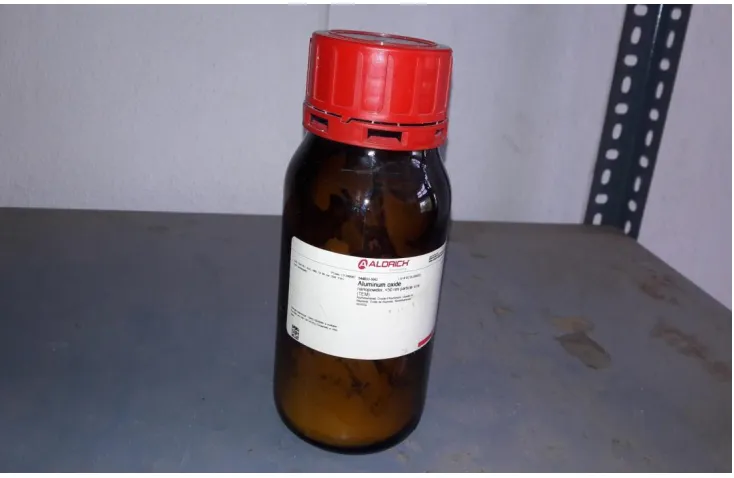
Figure 6 Aluminum oxide (Al2O3) nano powder
This vapor moves to the adiabatic section, in
the adiabatic section there is no heat loss
occur, because insulation rope is winded in
the adiabatic section. And then vapor moves
to the condenser section, in the condenser
section vapor gets cooled and converts into
the liquid. The vapors in the condenser
section are cooled by the external supplying
of water through the steel pipe. This liquid is
collected from the heat pipe through the
water container. And then we take the
temperature readings of working fluid
(Al2O3) by using thermocouple wires. The
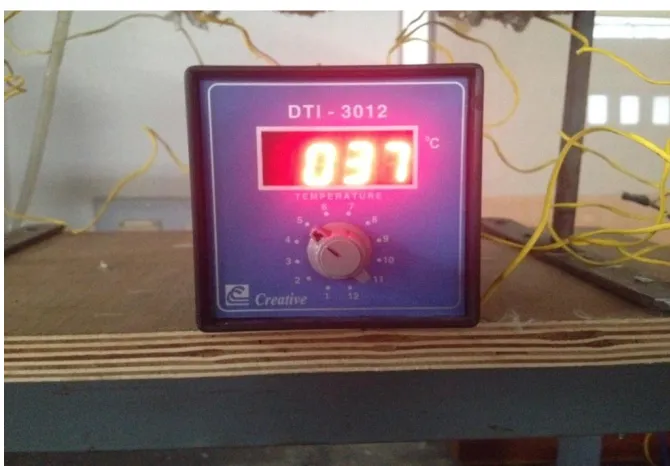
temperature readings are displayed in digital
temperature indicator. All thermocouple
wires are attached to the digital temperature
indicator. We take all the temperature
readings and note down in the book. The
temperature readings are shown in the
Available online: https://edupediapublications.org/journals/index.php/IJR/ P a g e | 1203
Figure 7 Copper fins
Tabular Columns
Table 1. Temperature readings of the working fluid (water) in the heat pipe
S.No Volts
(V)
Amperes
(I)
Power
(P)=VXI
(W)
(T1)
(oC)
(T2)
(oC)
(T3)
(oC)
(T4)
(oC)
(T5)
(oC)
1 80 0.22 17.6 55 31 35 43 45
2 110 0.27 29.7 66 24 30 42 48
3 150 0.35 52.5 82 17 23 38 53
4 180 0.41 73.8 96 8 15 35 53
5 220 0.46 101.2 117 5 7 38 63
6 280 0.55 154 150 4 6 33 70
Where T1, T2, T3, T4, T5 are Temperature readings in different sections of the heat pipe
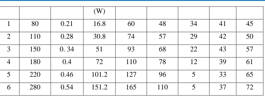
Table 2. Temperature readings of the working fluid (Nano fluid (Al2O3)) in the heat pipe
S.No Volts
(V)
Amperes
(I)
Power
(P)=VXI
(T1)
(oC)
(T2)
(oC)
(T3)
(oC)
(T4)
(oC)
(T5)
Available online: https://edupediapublications.org/journals/index.php/IJR/ P a g e | 1204
(W)
1 80 0.21 16.8 60 48 34 41 45
2 110 0.28 30.8 74 57 29 42 50
3 150 0. 34 51 93 68 22 43 57
4 180 0.4 72 110 78 12 39 61
5 220 0.46 101.2 127 96 5 33 65
6 280 0.54 151.2 165 110 5 37 72
Where T1, T2, T3, T4, T5 are Temperature readings in different sections of the heat pipe
Table 3. Properties of Nano Particles
Type of Nano particle Density of particle
(kg/m3)
Specific heat of particle
(J/kg.k)
Al2O3 (44nm) 3600 765
Sio2 (20nm) 2220 745
Zno (77nm) 5600 514
The Specific heat of water is 4.187 kJ/kg.K
The Specific heat of Nano fluid (Al2O3) is calculated by using following formula.
The widely used models of Pak and Cho [5] assume that nanofluids are homogeneous substances
that could be calculated by mixing theory as follows
Cp,nf
= ØCp,np
+(
1– Ø)Cp,b
Where
Cp,nf
is the specific heat of nanofluids,Cp,np is the specific heat of nanoparticles,
Cp,b is
the specific heat of the base fluid and
Ø
is the concentration by volume.Available online: https://edupediapublications.org/journals/index.php/IJR/ P a g e | 1205
We used concentration 0. 1% in this experiment and volume of working fluid is 270 ml. So we
can calculate
Ø
asØ =
0. 1/270 = 3.7037 x 10⁻⁴Substitute
Ø
value in the below equation, we can getCp,nf
= ØCp,np
+(
1– Ø)Cp,b
Cp,nf
= 3.7037 x 10−4 x 765 + (1−3.7037 x 10−4) x 4.187Cp,nf
= 0.28333305 +(0.99962963) x 4.187Cp,nf
= 0.28333305 + 4.1854499261Cp,nf
= 4.468782311 KJ/ kg.kHeat transfer rate for working fluid (water):
The Specific heat of water is 4.187 KJ/ kg.k
Q = mC
p∆T
∆T = T1 – T5
Mass of the liquid = 1000 gms
At power 17.6 W
∆T = T1 – T5
∆T = 55 – 45
∆T = 10 oC
1) Q= mCp∆T
Q = 1000 x 4.187 x 10
Q = 41870 J
Q = 41.87 KJ
Available online: https://edupediapublications.org/journals/index.php/IJR/ P a g e | 1206
∆T = T1 – T5
∆T = 150 – 70
∆T = 80 oC
2) Q= mCp∆T
Q = 1000 x 4.187 x 80
Q = 334960 J
Q =334.960 KJ
Similarly We are Calculating Heat transfer rate for working fluid (Nano fluid (Al2O3)):
The Specific heat of water is 4.4687 KJ/ kg.k
Q = mC
p∆T
∆T = T1 – T5
Mass of the liquid = 1000 gms
At power 16.8 W
∆T = T1 – T5
∆T = 60 – 45
∆T = 15 oC
1) Q = mCp∆T
Q = 1000 x 4.4687 x 15 Q = 67030.5 J
Q = 67.0305 KJ
At power 151.2 W
∆T = T1 – T5
∆T = 165 – 72
Available online: https://edupediapublications.org/journals/index.php/IJR/ P a g e | 1207
2) Q = mCp∆T
Q = 1000 x 4.4687 x 73 Q = 415589.1 J
Q = 415.5891 KJ
Heat transfer rate difference between the working fluids water and Nano fluid (Al2O3)
Q = Q2 – Q1
Q1 is the Heat transfer rate of water
Q2 is the Heat transfer rate of Nano fluid (Al2O3)
Q is the Heat transfer rate difference between the working fluids water and Nano fluid (Al2O3)
At power 16.8 W
Q = Q2 – Q1
Q = 67.0305 – 41.87
Q = 25.1605 KJ
At power 151.2 W
Q = Q2 – Q1
Q = 415.5891 – 334.960
Q = 80.6291 KJ
Graphs Plotted between Power input Vs Heater temperature and Power input Vs Discharge
Available online: https://edupediapublications.org/journals/index.php/IJR/ P a g e | 1208
Graph 1 Power input Vs Discharge temperature
Graph 2 Power input Vs Heater temperature 0 10 20 30 40 50 60 70 80
0 50 100 150 200
D isch ar ge Tem p e ratu re Power Input
Power Input vs Discharge Temperature
Power input vs discharge temperature (water) power input vs disharge temperature (nano fluid)
0 20 40 60 80 100 120 140 160 180
0 50 100 150 200
He at e r Te m p e ra tu re Power Input
Power Input vs Heater Temperature
Available online: https://edupediapublications.org/journals/index.php/IJR/ P a g e | 1209
Above graphs shows that Nano fluid has
high heat dissipation capacity and Nanofluid
increases the Thermal Conductivity
Performance.
IV. RESULTS
The comparison between the working fluid
(water) and working fluid (Nano
fluid(Al2O3)) heat transfer rates are
calculated. The heat transfer rate of the
Nano fluid is very high. In this work the
maximum heat transfer rate of the working
fluid (water) is 334.960 KJ and the
maximum heat transfer rate of the working
fluid (Nano fluid(Al2O3)) is 415.5891 KJ.
V. CONCLUSION
The heat transfer rates of the working fluid
(water) and working fluid (Nano
fluid(Al2O3)) are observed and Nano fluid
increases the Thermal Conductivity
Performance and Nano fluid has the high
heat dissipation capacity because Nano
Powder has high Thermal Conductivity
Property so Nano fluid gives the high heat
transfer rate.
VI. REFERENCES
[1] M. Nishikawara, H. Nagano
Department of Mechanical Engineering,
Toyohashi University of Technology, 1-1,
Hibarigaoka, Tempaku, Toyohashi, Aichi
441-8580, JapanDepartment of Mechanical
Science and Engineering, Nagoya
University, Furo, Chikusa, Nagoya
464-8603, Japan
[2] P. Gunnasegaran, M.Z. Abdullah,
N.H. Shuaib , Centre for Advanced
Computational Engineering (CACE),
College of Engineering, Universiti Tenaga
Nasional, Putrajaya Campus, Jalan
IKRAM-UNITEN, 43000 Kajang, Malaysia, School
of Mechanical Engineering, Universiti Sains
Malaysia, Engineering Campus, 14300
Nibong Tebal, Penang, Malaysia, TNB
Research Sdn. Bhd., Tenaga Nasional
Berhad, Jalan Ayer-Hitam, 43000 Kajang,
Malaysia
[3] Nandy Putra,Rosari Saleh, Wayan
Nata Septiadi, Ashar Okta, Zein Hamid,
Heat Transfer Laboratory, Department of
Mechanical Engineering University of
Indonesia, Kampus UI, Depok 16424,
Indonesia, Departemen Fisika, Fakultas
MIPA-Universitas Indonesia, Kampus UI,
Depok 16426, Indonesia
[4] Balewgize Amare Zeru
,CSIR-Central Mechanical Engineering Research
Available online: https://edupediapublications.org/journals/index.php/IJR/ P a g e | 1210
[5] CSIR-CMERI Durgapur, India,
Mechanical Engineering Department Jimma
institute of Technology Jimma,
Ethiopia
[6] Pak, B. C.; Cho, Y. I. Hydrodynamic
and Heat Transfer Study of Dispersed Fluids
with Submicron Metallic Oxide Particles.
Exp. Heat Transfer, 1998, 11, 151-170.
Authors
M.Lava Kumar Completed his M.Tech, presently working as Assistant Professor in G.PullaReddy Engineering College,Kurnool.
His Research Interest includes Heat
Transfer,Nanofluids and Heat Exchangers.
P.Rakesh kumar currently Pursuing my
M.Tech in G.PullaReddy Engineering