A Base-Band Wireless Spectrum Hypervisor for
Multiplexing Concurrent OFDM signals
Felipe A. P. de Figueiredo
∗, Ruben Mennes
‡, Irfan Jabandˇzi´c
∗, Xianjun Jiao
∗, and Ingrid Moerman
∗∗
Ghent University - imec, IDLab, Department of Information Technology, Ghent, Belgium.
‡
Department of Computer Science, University of Antwerp - imec, Antwerp, Belgium.
Email:
∗[felipe.pereira, irfan.jabandzic, xianjun.jiao, ingrid.moerman]@ugent.be,
‡[email protected]
Abstract—The next generation of wireless and mobile networks will have to handle a significant increase in traffic load compared to the actual one. This situation calls for novel ways to increase the spectral efficiency. Therefore in this paper, we propose a wireless spectrum hypervisor architecture that abstracts a radio frequency (RF) front-end into a configurable number of virtual RF front-ends. The proposed architecture has the ability to enable flexible spectrum access in existing wireless and mobile networks, which is a challenging task due to the limited spectrum programmability,i.e., the capability a system has to change the spectral properties of a given signal to fit an arbitrary frequency allocation. The main goal of the proposed approach is to improve spectral efficiency by efficiently using vacant gaps in congested spectrum-bandwidths or adopting network densification through infrastructure sharing. We demonstrate mathematically how our proposed approach works and present several simulation results proving its functionality and efficiency. Additionally, we designed and implemented an open-source and free proof of concept prototype of the proposed architecture, which can be used by researchers and developers to run experiments or extend the concept to other applications. We present several experimental results used to validate the proposed prototype. We demonstrate that the prototype can easily handle up to12concurrent physical layers.
Index Terms—radio virtualization, software-defined radio, net-work densification, infrastructure sharing, multi-tenancy, cogni-tive radios.
I. INTRODUCTION
According to [1], the average mobile connection speed in
2016was 6.8 Mbps and it is forecast to grow at a compound annual growth rate (CAGR) of 24.4 percent, reaching nearly
20.4Mbps by 2021. By2020it is forecast that there will be
11.6 billion mobile-connected devices, including Machine to Machine (M2M) modules [1]. Reports like [2] state that future mobile networks will need to support1million connections per square kilometer and up to a total of100 billion connections in total.
In order to support the expected growth in capacity, the forecast for the future mobile networks, the area throughput,
i.e., bit/s/km2, needs to be increased. Some ways to improve
area throughput in cellular networks include densification of existing cellular networks using extra-small cells, provision of peer-to-peer (P2P) communications, multi-tier heterogeneous networks, full duplex communication, massive multiple-input-multiple-output (massive MIMO), millimeter-wave technolo-gies, cognitive radios, beam division multiple access (BDMA),
cloud-based radio access networks (CRAN) and wireless net-works virtualization (WNV) [3]–[5].
One of the key features to achieve the forecast high data rates is the dense deployment of remote radio heads (RRHs). RRH is the name given to the RF front-end in mobile networks and encompasses the BS’s RF circuitry plus analog-to-digital/digital-to-analog converters and up/down converters. The dense deployment of RRHs can be achieved, with a rela-tively lower cost when compared to the deployment of several physical RRHs, by multiplexing several different signals at a single RRH and transmitting them over several virtual RRHs. Carrier aggregation is one of the usage examples, where a base station (BS) increases its capacity by allocating more spectrum bandwidth. Infrastructure sharing is another usage example, where densification is achieved by sharing already deployed pieces of equipment, such as the RRH, among several wireless or mobile networks [6].
Infrastructure sharing has the advantage of reducing capital expenditure. It is well known that the deployment of cellular or wireless networks is expensive, and raising the capital for that effort is quite difficult as the operators always want to make the most out of the already deployed infrastructure. Therefore, in order to obtain a better return on the costs related to installation and maintenance of mobile or wireless infrastructure, it would be less expensive to share the already (or newly) deployed infrastructure with other operators than to build overlapping and concurrent infrastructure [7].
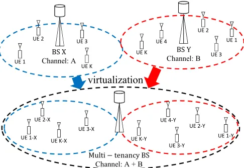
This way, RF front-end virtualization becomes very useful for flexible spectrum access, once it allows several physical layers (PHYs) to concurrently share a single physical wide-band RF front-end. Some direct consequences of RF front-end virtualization are the reduction in the required physical space for deployment (only a single wide-band RRH is required), energy consumption and price (reduction in redundancy) for the infrastructure provider. Figure 1 shows a multi-tenancy example where a single BS emulates several BSs where subscribers from different networks associate with their cor-responding virtual BS.
Another way of achieving such demanding rates is through better utilization of the available and already underutilized spectrum bands. In general, due to the presence of primary and secondary users in shared licensed bands and of competing (i.e., opportunistic) users in unlicensed bands, the available spectrum for users in a cognitive radio environment is frag-mented and its use is intermittent,i.e., the available spectrum
BS X
Channel: A UE 1
BS Y
Channel: B
Multi − tenancy BS
Channel: A + B
UE 2 UE 3
UE K
UE 1 UE 2
UE 3 UE 4
UE K
UE 1-Y UE 2-Y
UE 3-Y UE 4-Y
UE K-Y
virtualization
UE 1-X UE 2-X
UE 3-X UE K-X
Fig. 1: A single base station emulating multiple virtual base stations. Sub-scribers from different networks associate with corresponding virtual BS although they use the same underlying infrastructure.
is split into non-contiguous chunks and is not used all the time. This intermittent and fragmented spectrum availability calls for a flexible and agile transmission scheme of the desired signals [8]. The concurrent transmission of several narrow orthogonal frequency-division multiplexing (OFDM)-based signals allows for the selective use of the available chunks of spectrum, which enhances the spectrum utilization, consequently improving the area throughput.
Therefore, in this work, we propose a non-intrusive and highly optimized wireless hypervisor architecture for software-defined radios (SDRs) that ensures coexistence, isolation, and programmability for multi-carrier-based systems (i.e., OFDM) such as Wi-Fi, WiMAX, LTE, NB-IoT, etc. We focus on supporting OFDM-based systems once such waveform is still one of the most used and important ones being used even in 5G standards like the 5G New-Radio (NR) ones [9, 10]. Therefore, we understand that OFDM will still be widely adopted and employed for a long time.
We show that with the proposed architecture, spectrum pro-grammability (i.e., the ability to program/change frequency, bandwidth and gain settings) can be decoupled from physical layer (PHY) processing and delegated to a virtualization layer, (i.e., the wireless hypervisor) which is added between a set of virtual PHYs (vPHYs) and the hardware/physical radio fre-quency (RF) front-end. The proposed solution can be applied to both of the approaches mentioned above of achieving higher area throughput.
We demonstrate that spectrum allocation can be decoupled from the PHY (or base-band processing) layer. In this way, the proposed hypervisor architecture supports flexible spec-trum bandwidth allocation by creating a new layer located between several vPHYs and the physical RF front-end. The hypervisor dynamically maps the modulated signals of several vPHYs into configurable chunks of spectrum, before sending the resulting multiplexed signal of the vPHYs to the RF front-end. The hypervisor layer, which can be seen as a spectrum mapping/allocation layer, abstracts the underlying spectrum bandwidth dynamics and provides the vPHYs with a contiguous or non-contiguous (depending on the application
of the proposed architecture) set of frequency subcarriers (i.e., virtual spectrum bandwidth), where the desired spectrum bandwidth can be pre-defined (by operators for instance) or requested in an on-line basis by the vPHY itself.
Additionally, we present an open-source and free proof of concept prototype that was developed in order to assess the performance of proposed spectrum hypervisor architecture in real-world experiments. The source-code is available at [40] and can be used by researchers and developers to easily run experiments or extend the concept to other applications.
The remainder of the work is organised as follows. In section II, we present some aspects of hardware virtualization. In section III, we describe, mathematically, how we multiplex several OFDM signals. Next, in section IV, we list and discuss some important use cases where the proposed architecture can be employed. In section V we present and compare some related pieces of work on virtualization. Then, in section VI, we describe the proof of concept prototype developed in order to assess the feasibility of the proposed architecture. In section VII, some simulation results are presented showing the performance of the proposed architecture. Next, in section VIII, we present several experimental results obtained with the prototype. Finally, in section IX, we conclude our work with some conclusions and future work.
II. HARDWAREVIRTUALIZATION
Hardware (in our case, the RF front-end) virtualization is achieved by means of hypervisors [11, 12]. A hypervisor is a hardware virtualization technique that abstracts,i.e., isolates, multiple concurrent software radio protocol stacks (e.g., LTE, NB-IoT, Wi-Fi, etc.), also known as software-defined radios (SDR), from the underlying radio hardwarei.e., RF front-end. It allows multiple radio stacks to run on top of a single piece of radio hardware at the same time, i.e., concurrently, such that each protocol stack appears to have its own RF front-end (virtual RF front-end) that can be operated independently. One advantage is that wireless hypervisors help to maximize the effective use of the deployed infrastructure (i.e., servers, RF front-ends, etc.).
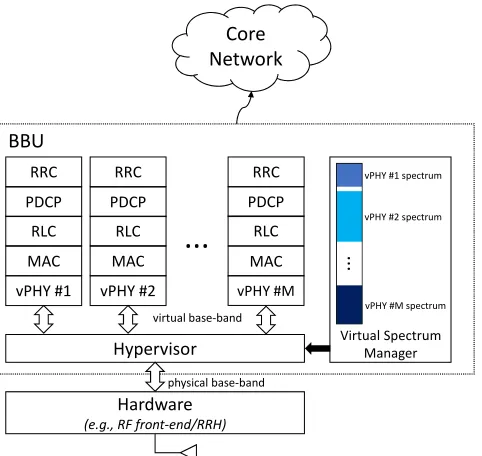
The hypervisor is the mechanism allowing the seamless sharing of a particular resource by meeting three key re-quirements: abstraction, programmability, and isolation. The proposed solution addresses each of these requirements as shown in Figure 2 and briefly described next.
• Abstraction: this feature hides the underlying hardware
characteristics and establishes simplified interfaces for accessing and sharing the hardware resources. This fea-ture allows the clients of the hypervisor architecfea-ture to use it with no change to their upper layer radio stack,
Hardware (e.g., RF front-end/RRH)
Hypervisor
physical base-band vPHY #1
virtual base-band BBU
...
vPHY #1 spectrum vPHY #2 spectrum
vPHY #M spectrum
Virtual Spectrum Manager Core
Network
MAC RLC PDCP
vPHY #2 MAC
RLC PDCP
vPHY #M MAC
RLC PDCP
RRC RRC RRC
...
Fig. 2: High-level view of a hardware hypervisor in a 4G-like network.
physical RF front-end. The vPHYs are the point of access of the radio stacks to the virtual RF front-ends. Along with the hypervisor, the vPHYs provide a computationally efficient way of multiplexing several base-band signals into a wide-band signal, which consequently splits the spectrum bandwidth provided by the physical front-end. The proposed architecture supports the operation of mul-tiple concurrent vPHYs, implementing totally different air-interfaces (as long as they are OFDM-based signals and have subcarrier spacings that are integer multiples of the smallest adopted spacing) with diverse processing constraints, channel bandwidths, medium access schemes, etc.
• Programmability: the proposed wireless hypervisor has
to provide the multiple radio stacks running on top of it the same level of programmability (or configurability) provided by the single physical RF front-end. This feature is addressed by allowing the multiple radio stacks to configure different center frequencies, bandwidths and transmission/reception gains for individual virtual RF front-ends, i.e., the virtual RF front-ends must provide the same set of functionalities provided by the physical RF front-end.
• Isolation: the proposed wireless hypervisor must make
sure that any configuration or wrong configuration does not affect or cause interference to any other collocated radio stack. Isolation is the fundamental requirement that guarantees fault tolerance, security, and privacy to the multiple radio stacks running (i.e., coexisting) on top of the same physical RF front-end [12]. This feature is enforced across multiple clients by providing them predefined access-points and bandwidths that do not overlap.
Figure 2 shows one out of several possible multi-tenancy uses for the proposed architecture, where it is employed in
20 MHz channel - A 20 MHz channel - B
Fig. 3: Flexible and dynamic spectrum access example. Communications spectrum bandwidths can be flexibly and dynamically changed according to the availability of spectrum as well as application requirements.
4G-like mobile networks. However, it could be, for example, employed by Internet Service Providers (ISP) aiming at shar-ing their already deployed Wi-Fi access-points (or hot-spots) at locations such as airports, cafes and common shopping areas. Figure 3 depicts yet another use case example regarding dynamic and flexible spectrum access. In the current wireless communications networks, channels have fixed central fre-quencies and bandwidths. Such static channel allocation causes spectrum fragmentation, lowering the spectrum utilization efficiency. Figure 3 shows a common coexistence scenario in industrial, scientific and medical (ISM) bands. In these bands it is common to have the coexistence of several different technologies, such as Wi-Fi, IEEE 802.15.4 (e.g., ZigBee), LTE-U, etc. [13]. In the figure, two IEEE 802.15.4 networks occupy two channels that overlap with a20MHz-wide Wi-Fi channel. As can be seen, the two IEEE 802.15.4 networks may render the channel unusable for Wi-Fi communications due to the narrow-band interference caused by the two IEEE 802.15.4 networks. However, the remaining fragmented spectrum in that channel could be used by a flexible and dynamic system, as depicted by the red-dashed lines in Figure 3. As it is shown, the spectrum gaps created by the IEEE 802.15.4 transmissions could be used to establish LTE-like networks (e.g., LTE-U, NB-IoT, etc.) or any other kind of OFDM-based network. This flexible and dynamic spectrum usage completely removes the concept of pre-defined and static channel allocations. Based on this approach, frequencies and bandwidths can be dynamically allocated based on the availability of spectrum and the requirements of the applications.
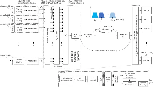
III. MULTIPLEXINGCONCURRENTOFDM SIGNALS In this section, we present a mathematical analysis of the working of the hypervisor proposed in this work and depicted in Figure 4.
P/S AddCP Su bc arrier Ma ppi ng Modulation N -po in t I FFT .. .
Modulation ...
Modulation ...
N modulation symbols, e.g., QPSK, 16QAM, 64QAM, etc.
Modulation ...
...
...
...
Channel RF Front-End RF Front-End M channelsN = M ×N
Channel Coding vPHY #0 Channel Coding Channel Coding Channel Coding
...
vPHY #1 vPHY #2 vPHY #M -1e.g., turbo codes, convolutional codes, etc.
Data packet #0
Data packet #1
Data packet #2
Data packet #M-1
vPHY #0 vPHY #1 vPHY #M-1 vPHY #2
...
Time/Frequency Synchronization CFO Correction CP Removal N -point FFT Pilot extraction & Channel Estimation Channel Equalization Channel Decoding Data packet vPHY #kRate: N ×∆
Bas e-ban d Spec trum Hype rvis or Chann eliz er ( e.g. , fr equency do mai n, po lypha se filt erbank , et c.) Su bcarrier Dem app er
S/P ... ...
...
frequency
N N subcarriers including nulled ones.
Rate: = M ×N ×∆
Fig. 4: Architecture of the proposed base-band wireless hypervisor.
length of the IFFT used in the hypervisor andbccis known as the floor operator and gives the largest integer value that is less than or equal toc. Out of theNvPHYsubcarriers, a narrow sub-band might have, NU
vPHYcarrying useful information, i.e., the modulation symbols si, one Direct Current (DC) subcarrier, NvPHYDC , which is set to zero, andNvPHYN ullsubcarriers that are also set to zero. The nulled subcarriers can be used as frequency guard-bands at both edges of the narrow sub-band, allowing for the straightforward realization of anti-aliasing filters. On the other hand, the DC subcarrier allows the use of the simpler and cheaper direct-conversion, also known as zero intermediate-frequency (IF), RF front-ends. The narrow sub-band signal can be defined as
Bk(i) =
0, i= 0,
si, 1≤i≤ NU
vPHY
2 ,
0, (NvPHYU
2 ) + 1≤i≤(
NU
vPHY
2 ) +N
N ull
vPHY,
si, ( NU
vPHY
2 ) +N
N ull
vPHY+ 1≤i≤NvPHY−1. (1)
For the sake of clarity, we consider that N is split into
M sub-bands with NvPHY subcarriers and that the subcarrier mapping block in the hypervisor maps complex samples into contiguous sub-bands. Note that the mapping of the M sub-bands,Bk(i), into the IFFT subcarriers/bins corresponds to a frequency translation (mixing) of the sub-band signal, which is centered around 0 [Hz], to a frequency offset defined by the bin number times the subcarrier spacing,∆f =Rhyper/N, where Rhyper is the sampling rate used by the hypervisor. The hypervisor’s sampling rate, Rhyper, defines the amount of physical spectrum bandwidth that it can virtualize.
The set, S(i), containing the concatenation of all the M
narrow sub-bands,Bk(i), and of lengthN is transformed into time domain using an IFFT of sizeN as
s(n) = 1
N N−1
X
i=0
S(i)e−j2πin/N
= 1
N M−1
X
k=0
NvPHY−1 X
i0=0
Bk(i0)e−j2πin/N,
(2)
where i= i0+kNvPHY. Then, based on (2), the transmitted wide-band signal, ywBB(n), including a gain factor and the appending of a cyclic prefix can be represented by
ywBB(n) =
1
N M−1
X
k=0
NvPHY−1
X
i0=0
ρkBk(i0)e−j2π(i
0+kNvPHY)n/N
,
−NCP ≤n≤N−1,
(3)
whereρk is the frequency amplification factor (or frequency gain), varying from 0 to1, applied individually to each sub-band and NCP is the cyclic-prefix (CP) length, which is an integer multiple ofM. As can be noticed,ywBB(n)is a wide-band signal containing all the M multiplexed vPHY signals. As the final step in the transmission chain, the wide-band signalywBB(n)is sent to the RF front-end, which will translate the signal into the desired pass-band frequency.
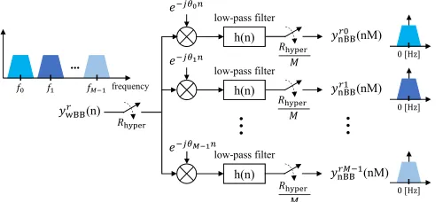
consequently, it is perfectly received at the receiver side. Next, after the frequency translation, the received wide base-band signalyr
wBB(n) =ywBB(n), which contains theM multiplexed sub-band (narrow-band) signals, is digitally translated/split intoM narrow base-band signals (each one centered around0
[Hz]), bandwidth restricted by low-pass digital Finite Impulse Response (FIR) filters, and finally, submitted to a sample rate reduction. These steps are depicted in Figure 5, which shows the architecture of a conventional channelizer as described in [14]. As shown in the figure, the output of the k-th channel, which is denoted by yrk
wBB, prior to the down-sampling, is a convolution as defined by
yrk
wBB(n) =
yrwBB(n)ejθkn ~h(n)
=
NFIR−1 X
l=0
ywBBr (n−l)ejθk(n−l)h(l),
0≤n < N+NFIR−1
(4)
where NFIR is the length of the FIR filter, θk = 2πδNkn is the angle corresponding to the digital frequency offset, andδk is the center-frequency of the k-th narrow sub-band, Bk, in number of subcarrier spacings,∆f. After substituting (3) into (4) we have
yrk
wBB(n) =
NFIR−1
X
l=0 1
N M−1
X
k=0
NvPHY−1
X
i0=0
ρkBk(i0)e
−j2πΘi0,k(n−l)
N h(l),
−NCP ≤n≤N−1,
(5) whereΘi0,k= (i0+kNvPHY−δk) mod N. The multiplication of yr
wBB(n) by ejθkn centers the k-th narrow sub-band, Bk, around 0 [Hz] and the convolution with the low-pass filter makes sure that only the signal components belonging to the
k-th narrow sub-band go through it while the other sub-bands are filtered out. This way, (5) can be re-written as
yrk
wBB(n) = 1
N N−1 X i=0
ρkBk(i)e
−j2πni
N , 0≤i≤NvPHY 2 ,
ρkBk(i)e
−j2πni
N , N−NvPHY
2 + 1≤i≤N−1,
0, otherwise,
−NCP ≤n≤N−1. (6) As can be seen by inspecting (6), out ofN subcarriers/bins, only the lower and upper NvPHY
2 bins contain useful values,i.e.,
values different from zero. We consider in (6), that the filters have a perfect window-shaped frequency response, which is not true in practice but can be approximated by well-designed high order low-pass filters [15].
Next, the wide base-band representation of thek-th narrow sub-band signal,yrk
wBB(n), is subject to a down-sampling oper-ation, as depicted in Figure 5, in order to have a narrow base-band representation of the sub-base-band signal, which can then be fed into a PHY for data decoding. After down-sampling, the signal expressed by (6), can be written as
yrk
wBB(nM) =
1
N N−1
X
i=0
F(i)e−N/Mj2πni, −N
CP ≤nM ≤N−1.
(7) h(n) low-pass filter h(n) low-pass filter h(n) low-pass filter
..
.
(n) ... frequency (nM) (nM) (nM) 0 [Hz] 0 [Hz] 0 [Hz]..
.
Fig. 5: Architecture of a conventional channelizer: frequency offset to base-band, low-pass filters, and down-samplers.
where the functionF(i)is defined as
F(i) =
ρkBk(i), 0≤i≤NvPHY2 ,
ρkBk(i), N−NvPHY2 + 1≤i≤N−1,
0, otherwise.
(8)
Next, after the down-sampling operation the complex pe-riodic signal e−j2Nπni has its periodicity reduced from N to N/M samples,e−N/Mj2πni, and therefore, we can rewrite (7) as
yrk
wBB(nM) =
1
N
"NvPHY−1 X
i=0
F(i)e−N/Mj2πni
+
2NvPHY−1
X
i=NvPHY
F(i)e−N/Mj2πni +· · ·+
M NvPHY−1
X
i=(M−1)NvPHY
F(i)e−N/Mj2πni
= 1
N NvPHY−1
X
i=0
"M−1
X
m=0
F(i+mNvPHY)
#
e
−j2πni
N/M ,
−NCP ≤nM ≤N−1.
(9)
From (8) we notice that only half of the first and last terms of the summation in (9) are different from0, and therefore, it can be re-written as
yrk
wBB(nM) =
1 N NvPHY 2 X i=0
F(i)e−N/Mj2πni
+1
N
NvPHY−1 X
i=NvPHY
2 +1
F(i+ (M −1)NvPHY)e
−j2πni
N/M ,
−NCP ≤nM ≤N−1.
(10)
Finally, by using (8) and remembering the fact thatN/M=
NvPHY, we show that the time-domain representation of thek -th narrow sub-band,Bk(i), is recovered by thek-th branch of the channelizer (see Figure 5)
yrk
nBB(n) =
1
N NvPHY−1
X
i=0
ρkBk(i)e
−j2πni
NvPHY ,
−NCPvPHY≤n≤NvPHY−1,
(11)
where NvPHY
CP = NCP/M is the cyclic prefix length of the vPHYs.
subcarriers of the hypervisor’s IFFT module. Additionally, it is also important to notice that each one of the narrow sub-bands, which are multiplexed by the hypervisor, can have different widths. The only requirement is that the width of individual sub-bands is a divisible multiple ofN. In this case, if a device is receiving more than one of the multiplexed narrow sub-band signals, then, it has to employ a non-uniform channelizer [16], as polyphase filter-bank channelizers only extract equally spaced spectrum chunks.
A. Discussion
In this section, we discuss the proposed architecture, its functionalities, features and possible uses.
As mathematically shown earlier, the proposed wireless hypervisor provides a virtual and discretized (in steps of
∆f =Rhyper/N) base-band spectrum abstraction layer to the several vPHY layers sitting on top of it. Its key function is the multiplexing, in the frequency domain, of several narrow base-band signals. It receives concurrent sets of modulated signals (e.g., BPSK, QPSK, M-QAM, etc.) from several vPHYs and maps these sets into continuous or non-contiguous subcarriers (i.e. spectrum) that will then be converted into time-domain by theN-point IFFT module and have a properNCP samples long CP added to it. The digital signal processing carried out by the spectrum hypervisor transforms the sets of modulated vPHY signals into a wide base-band waveform signal that is appropriate for transmission, while keeping the concurrent sets of vPHY signals unchanged and isolated from each other.
The hypervisor supports data flows from multiple concurrent vPHYs and provides each one of them a virtual RF front-end, which can have the following settings configured inde-pendently: frequency domain gain (ρk), frequency location (given by the mapping of the sub-band into the hypervisor’s IFFT) and bandwidth of the vPHY (NvPHY). Regarding the gain settings for each vPHY, as there is only one physical RF amplifier, the gain of the amplifier is set to a reasonable level (a level that avoids saturating the signal) and the independent vPHYs can set what we called frequency gain (ρk), which is a gain applied to the frequency domain signal and corresponds to a percentage (i.e., 0 up to 100 %) of the RF amplifier’s current gain.
Access to the wireless hypervisor is exposed through the vPHYs. The vPHYs work the same way as regular OFDM-based PHY layers (e.g., Wi-Fi, WiMAX, LTE, etc.) being the only exception the removal of the OFDM modulation part. In the proposed architecture (see Figure 4), OFDM modulation is now executed by the wireless hypervisor, which efficiently multiplexes the base-band signal of several vPHYs into a single wide base-band signal. By removing and transferring the OFDM modulation of all PHYs to the hypervisor, we optimize the whole base-band processing performance by avoiding redundant/unnecessary, for example FFT and IFFT, operations that would be required to multiplex several concurrent regular PHY signals into a wide base-band signal [17]–[19]. The down-side of our approach is that it can only operate with multi-carrier-based (i.e., OFDM) signals.
At the receiver side, different receiving approaches might be followed, depending on how the proposed hypervisor is
employed to generate the wide base-band signal. The first approach refers to a communications connection between two devices (i.e., a point-to-point connection). In this approach, as a first step, the received wide base-band signal coming from the RF front-end is split by a channelizer into equally or unequally (i.e., non-uniform) spaced spectrum chunks and then, the down-converted and down-sampled narrow sub-band signals are fed into the narrow-band PHY receivers running on the device. The second approach is similar to the first one, where the only difference is that the signal coming from the RF receiver front-end is not split into narrow sub-bands. Here the wide-band received signal is fed directly into the OFDM demodulator of a corresponding wide-band vPHY. In the third approach, several independent, distributed and narrow-band devices have their RF receiver front-ends tuned to the center frequency and transmission bandwidth of each one of the transmitted vPHY signals. The fourth approach represents a mix of the previous three approaches, where there could be wide-band devices tuning to more than one transmitted band vPHY signal while other narrow-band devices would only be tuning to individual transmitted narrow-band vPHY signals. In all the approaches mentioned above, the signal multiplexing carried out at the transmitter side is transparent to the PHY receivers, meaning that the radio stack at the receivers does not need to be modified.
IV. USECASES
In this section, we present and discuss some possible use cases for the proposed architecture.
A. Dynamic Spectrum Access
The Federal Communications Commission (FCC) has re-ported that licensed spectrum bandwidths are greatly under-used [20]. One of the examples mentioned in the report is the TV spectrum, which has one of the lowest utilization rates. That spectrum band is in most cases left totally unused in areas not so populated (e.g., rural areas), and due to that, it is referred to as TV white-space. Based on this under-utilization of spectrum originally meant only for TV broadcasting, regu-lators are opening up this previously licensed spectrum for unlicensed use [21]. TV white-spaces for unlicensed use brought about a revolution to cognitive radio, spectrum sensing as well as to dynamic spectrum access [22]. TV white-spaces allow for the opportunistic use of vacant TV channels for data communications [23, 24].
that correspond to vacant spectrum, i.e., not being used by the primary or other users. At the receiver side, the signal is demodulated and decoded as a wide-band NC-OFDM signal where some subcarriers had their values set to zero. The PHY receiver for this signal is depicted in the bottom right corner of Figure 4, and is nothing but a generic OFDM demodulator/decoder where the subcarrier demapper module needs to know beforehand which subcarriers are active during a given transmission interval [8].
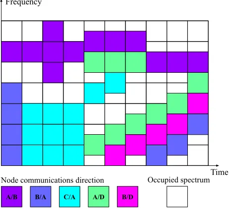
Figure 6 depicts a possible snapshot of the spectrum usage in the TV white-space when the proposed architecture is used as a dynamic packet-based PHY layer with allocated bandwidth being dynamically changed according to vacant spectrum. In this example, the PHY layer establishes concur-rent/simultaneous communications with several nodes. As can be seen, the channel’s center frequency and allocated trans-mission bandwidth are changed throughout time, depending on spectrum availability and/or traffic load.
Another use case for the proposed architecture is in the im-plementation of a spectrum sharing scheme between wireless operators and Fixed Satellite Services (FSS) in the Citizens Broadband Radio Service (CBRS) band. FSS stations must share spectrum with new entrant wireless operations, while the entrant networks must ensure that the interference that they introduce to the incumbent FSS remains below a specified threshold [26, 27]. The aim with the launch of CBRS in the USA is that wireless systems should dynamically share the spectrum among them [27]. In this use case, the proposed architecture could easily adapt its transmission bandwidth to the available (either continuous or discontinuous) spectrum at any specific time. This use case is similar to the one described by Figure 6. Mainly aligned with this use case, DARPA, the Defense Advanced Research Projects Agency from the United States, has started the Spectrum Collaboration Challenge with the aim to encourage research and develop-ment of smarter/more intelligent coexistence and collaboration techniques of heterogeneous networks in the same wireless spectrum bands [54, 55]. One of the examples they have been advocating for is the adoption of such spectrum-sharing technologies in the CBRS band [56].
B. Network Densification
The capacity of an additive white Gaussian noise (AWGN) channel is given by the following equation [6]
R < C =m
W
n
log2
1 + S
I+N
, (12)
where W is the BS allocated bandwidth, n denotes the BS load factor (i.e., the number of users sharing the given BS), m is the spatial multiplexing factor (i.e., it denotes the number of spatial data streams connecting the BS and devices), S gives the signal power and I and N represent the interference and power noise, respectively, experienced at the receiver side. After analyzing the equation, it is possible to see that the capacity can be increased by decreasing the BS load factor, which can be attained through cell splitting. Cell splitting involves deploying a larger number of BSs and
Time Frequency
A/B B/A C/A A/D B/D
Occupied spectrum Node communications direction
Fig. 6: Snapshot of the spectrum usage in the TV white-space.
making sure that the user traffic is evenly distributed among all the deployed BSs [6]. A possible consequence of cell splitting/densification is that it might improve the signal power, as the users could now be closer to the new deployed BS and consequently experiencing a reduced path-loss.
The dense deployment of infrastructure is a precondition for cutting the BS load-factor n down in (12). However, the deployment of additional BSs entails significant costs and detailed site survey/planning [25]. Therefore, another use case, which represents a very important application for the proposed architecture, is instantiating the proposed architecture as an RF front-end multiplexer, where several vPHYs share a single physical RF front-end. This could be employed in multi-tenancy cases [17], where a cellular network infrastructure provider shares their owned infrastructure and/or spectrum with mobile virtual network operators (MVNOs) or vertical markets such as energy, automotive, city management, food and agriculture, health-care, government, public transportation, manufacturing, etc. In this case, the infrastructure provider shares its already deployed infrastructure, which ranges from base-band processing units (BBUs) to the RF front-ends (also known as Remote Radio Head - RRH). By employing multi-tenancy schemes, operators, MVNOs and verticals can decrease their capital expenditure (CAPEX) and operational expenditure (OPEX). Multi-tenancy makes the deployed in-frastructure more energy efficient/greener by allowing a re-duced number of BS sites, and, therefore, largely reducing the power consumption of air conditioning and other site support pieces of equipment.
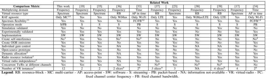
TABLE I: COMPARISON OF RELATED WORKS.
Related Work
Comparison Metric This work [19] [35] [36] [33] [37] [23] [38] [39] [17] [34]
Multiplexing domain Frequency Frequency Frequency Frequency Time Frequency Frequency Frequency Frequency Frequency Time
Virtual resource type Spectrum Spectrum Spectrum RB AP in time RB Spectrum RB RB Spectrum AP in time
RAT agnostic Only MC10 Yes Yes Only WiMax Only Wi-Fi Only LTE Yes Only WiMax/LTE Only LTE Yes Only Wi-Fi
Spectrum flexibility11 Yes Yes Yes Yes FC/FB12 Yes Yes Yes Yes Yes FC/FB12
Operation mode S/PB S S S PB S S S S S PB
Simulation validated Yes No No Yes No No No No Yes No No
Experimentally validated Yes Yes Yes Yes Yes Yes Yes No No Yes Yes
Implementation SW SW SW SW SW SW SW SW SW SW SW
Create self-interference No1 Yes Yes No1 No2 No Yes No No Yes No2
Create OOB emissions Yes Yes Yes No Yes No Yes No No Yes Yes
Individual gain control Yes Yes Yes NA No No Yes NA NA No No
Open-source prototype Yes Yes Yes No No No No No No Yes No
Dynamic allocation3 Yes No Yes NA Yes Yes No Yes Yes No Yes
Radio resource isolation4 Yes Yes Yes Yes Yes Yes Yes Yes Yes Yes Yes
Virtual radio independence5 Yes No Yes NA Yes Yes Yes Yes Yes Yes Yes
Concurrent Tx/Rx at different channels Yes Yes Yes Yes No No6 Yes No6 No6 Yes No
Number of VR instances7 12 2 2 2 slices9 28 3 slices9 3 NA 4 slices9 4 28
Legend: RB: resource-block - MC: multi-carrier - AP: access-point - SW: software - S: streaming - PB: packet-based - NA: information not-available - VR: virtual-radio - FC: fixed channel center frequency - FB: fixed channel bandwidth.
1OFDM based systems do not create self-interference as the subcarriers are mutually orthogonal. 2Once it time-multiplexes the access-point.
3Allow on demand destruction and creation of VRs without interrupting the operation of the spectrum hypervisor or other VRs. 4Allocate non-overlapping sub-bands to different VRs and prevent interference among VRs,e.g., guard bands.
5Ensure that VRs cannot interfere with the operation and performance of other VRs, even in the case of a malfunctioning or misbehaving VRs. 6Use the concept of virtual RBs, therefore, concurrent transmissions only happen at different RBs within the same channel.
7The maximum number of VRs instantiated during the experiments. 8A single AP PHY that is time-shared between two VRs.
9A single PHY layer that has its RBs split into slices, creating VRs. 10Optimized for multi-carrier-based wave-forms,e.g., OFDM.
11Flexibility in setting different channel center frequencies and bandwidths to different concurrent VRs.
12The approach only works with fixed channel center frequencies and bandwidths as it time-multiplexes a Wi-Fi AP.
step in the direction of multi-tenancy networks as being studied by the 3GPP [31].
This possible application/instantiation of the proposed archi-tecture enables the Radio Access Network (RAN) to be made available as a service (RANaaS) to MVNOs and verticals. Virtual PHYs create new ways for infrastructure providers to monetize their owned spectrum bandwidth and deployed infrastructure. In this way, infrastructure providers can offer virtual PHYs as a service (vPHYaaS) in order to provide isolated and independent virtual networks to MNVOs and/or verticals sitting on the top of a shared physical infrastructure [32]. For this use case, a BBU, providing vPHYs as a service to MNVOs/verticals/operators, would have the proposed hyper-visor architecture multiplexing the signal of several vPHY at downlink side while a channelizer would be deployed at uplink side in order to provide each one of the vPHYs with a signal corresponding to its allocated bandwidth, just as depicted in Figure 4. This use case is aligned with standardization efforts made by 3GPP that consider a BS serving both LTE and NB-IoT users [32].
V. RELATEDWORK
In this section, we describe and discuss some related pieces of work on virtualization.
The related works on virtualization can be split into two main categories, or frequency-multiplexing. The time-multiplexing approaches achieve virtualization by splitting the access time to a common Wi-Fi access point PHY layer [33, 34]. This is possible due to the fact that Wi-Fi is a packet-based wireless network, where access points do not transmit data all the time, and therefore, being able to allow virtual Wi-Fi radio stacks to use its idle time. The frequency-multiplexing
approaches can be further divided into two sub-categories based on the type of the virtualized resource, which can be the spectrum bandwidth through the virtualization of the RF front-end [17]–[19, 23, 35] or the time-frequency resource grid through the virtualization of the resource blocks (RB) provided by Orthogonal Frequency-Division Multiple Access (OFDMA)-based radio technologies such as LTE and WiMax [36]–[39].
Out of all the compared related works, only a few are technology agnostic, i.e., can provide virtual radios to any radio access technology (RAT) [17]–[19, 23, 35]. However, the issue with these works is that they exchange optimized performance for being generalized so that they can operate with different RATs. In most of these works [17]–[19, 35], in order to be agnostic, the hypervisor layer re-implements operations (e.g., FFT, IFFT, Sub-carrier Mapper, etc.) that are already performed by the PHY layers of the individual RATs, creating an extra overhead that decreases the performance of the solution.
An important comparison point is the dynamic creation and destruction of virtual radios without interfering with or stopping the hypervisor or other already instantiated virtual radios. Out of all works, only a few do not support such feature [17]–[19, 23, 36], where the number of instantiated virtual radios and their respective bandwidth allocations must be configured before running the hypervisor.
with12concurrently running vPHYs.
Finally, it is also important to add that independent gain configuration is an important feature to be exposed to the virtual radios once, for example, devices might be at totally different locations, however, it seems that independent gain configuration is not a major concern to most of the related works, once only a very few mention its support [19, 23, 35]. Differently from the other compared works, the virtualiza-tion architecture proposed in this work was designed to be highly optimized for sharing the same underlying physical RF front-end among several concurrent multi-carrier based virtual radios (i.e., vPHYs). It provides dynamic access to several concurrent and configurable virtual RF front-ends (e.g, frequency gain, frequency location, and bandwidth) that are accessed through multiple vPHYs. The vPHYs can be instan-tiated in real-time without interfering with running vPHYs and without the necessity to stop the hypervisor.
The majority of the compared related works do not make their source code available [23, 33, 34, 36]–[39], however, we believe that research on this field can only progress if the different implementations are made available for comparison and a better understanding of their functionalities and fea-tures. Therefore, we make our proposed architecture prototype available at GitHub [40]. The source code includes some examples to measure the prototype’s performance, a Graphical User Interface (GUI) for visualizing the transmitted spectrum and a channel emulator that can be used to run experiments without the necessity of having a dedicated piece of physical RF front-end. It emulates Additive White Gaussian Noise (AWGN), Rayleigh and Multi-path channels with several different Signal-to-Noise (SNR) values. The prototype makes extensive use of Single Instruction Multiple Data (SIMD) functions, including the FFT and IFFT implementations [41], making it even more optimized.
Table I presents a comprehensive comparison of related virtualization and hypervision works.
VI. PROOF OFCONCEPTPROTOTYPE
In this section we describe a proof of concept prototype developed in order to verify the performance of proposed spectrum hypervisor architecture in real-world experiments.
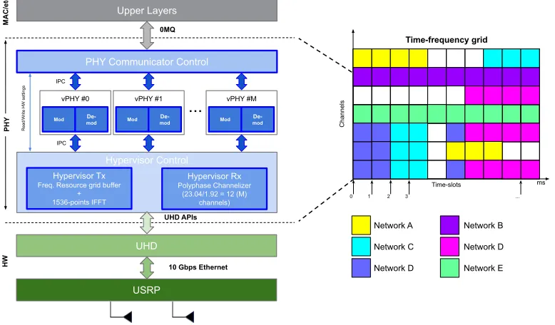
Figure 7 depicts the high-level architecture of the im-plementation of the proposed architecture. As can be seen, the prototype is composed of several modules, namely, PHY communicator control, M vPHYs, and the hypervisor control module, which is in turn, composed of the modules hypervisor Tx and Rx.
The prototype is an open-source software-defined PHY layer designed to multiplex and receive (i.e., demultiplex) the signal of several vPHYs [40]. It is implemented based on the srsLTE library [42]. srsLTE is an open-source and free LTE software-based library [42]. The prototype can run on top of several Ettus software-defined radio (SDR) devices such as the Ettus USRP X family or National Instruments’ (NI) RIO SDR devices [43, 44] by using the Universal Software Radio Peripheral (USRP) Hardware Driver (UHD) software Application Programming Interface (API) [13, 45]. Therefore,
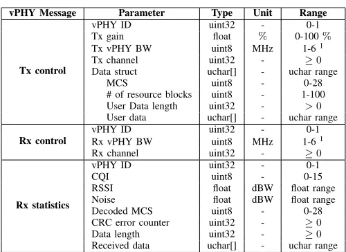
TABLE II: LIST OF MESSAGES AND THEIR RESPECTIVE PARAMETERS.
vPHY Message Parameter Type Unit Range
Tx control
vPHY ID uint32 - 0-1
Tx gain float % 0-100%
Tx vPHY BW uint8 MHz 1-61 Tx channel uint32 - ≥0
Data struct uchar[] - uchar range
MCS uint8 - 0-28
# of resource blocks uint8 - 1-100 User Data length uint32 - >0
User data uchar[] - uchar range
Rx control
vPHY ID uint32 - 0-1
Rx vPHY BW uint8 MHz 1-61 Rx channel uint32 - ≥0
Rx statistics
vPHY ID uint32 - 0-1
CQI uint8 - 0-15
RSSI float dBW float range Noise float dBW float range Decoded MCS uint8 - 0-28 CRC error counter uint32 - ≥0
Data length uint32 - ≥0
Received data uchar[] - uchar range
the prototype accesses the SDR device through the UHD driver and its APIs [46].
The communication between the prototype and the upper layers is carried out through a set of three well-defined messages, which are exchanged over a ZeroMQ bus [48],i.e., the prototype and the upper layers are interconnected through a publish-subscribe messaging system known as ZeroMQ [48]. ZeroMQ is a high-performance asynchronous messaging library, designed to be used in distributed or concurrent applications [48]. The set of vPHY messages is designed with Google’s Protocol Buffers (protobuf) [47]. Protobuf is used for data serialization and works perfectly with the 0MQ messaging library [48].
The first two vPHY messages, called, Tx and Rx Control, are used to control and configure the transmission and recep-tion of user data, respectively. The parameters in these two control vPHY messages should be configured and sent to the individual vPHYs by the upper layers before the transmission of every new subframe. Each vPHY control message, as the name suggests, controls the operation of only one vPHY. The remaining message, called Rx statistics vPHY message, is used to give upper layers feedback on the operation of each individual vPHY.
Tx controlmessages transport the user data to be
transmit-ted (i.e., TBs) and transmission parameters such as vPHY ID, vPHY Tx BW, MCS, Tx gain, Tx channel, number of resource blocks used by that user, data length, and data. The vPHY ID field is used in all messages to specify to which one of the vPHYs a control message is meant to or received from. Rx
control messages are used to configure reception parameters
such as vPHY ID, vPHY Rx BW, and Rx channel.
Rx statistics messages carry the vPHY ID, received
de-coded user data, and reception statistics such as Received Signal Strength Indication (RSSI), Channel Quality Indicator (CQI), decoded MCS, cyclic redundancy check (CRC) error counter, etc. The vPHY messages and their parameters are summarized in Table II.
UHD Upper Layers
PHY Communicator Control
...
IPC
vPHY #M
Mod De-mod
vPHY #0
Mod De-mod
vPHY #1
Mod De-mod
Hypervisor Tx Freq. Resource grid buffer
+ 1536-points IFFT
Hypervisor Rx Polyphase Channelizer
(23.04/1.92 = 12 (M) channels)
Hypervisor Control
IPC
Read/W
rite HW settings
0MQ
USRP
UHD APIs
10 Gbps Ethernet
MAC/etc.
PHY
HW
0 1
ms
2 3 ...
Time-frequency grid
Channels
Time-slots
Network A Network C Network D
Network B Network D Network E
Fig. 7: High-level architecture of the implemented prototype.
Next, we describe each one of the modules composing the prototype.
• PHY Communicator Control: this module is
respon-sible for the exchange of messages with several and possibly independent upper layers,e.g., the MAC layers from different users or operators. This module works on a subframe basis, meaning that the connected upper layers always send/receive in one control message to/from the module the content of a subframe as the minimum unit of data exchange. The received control messages, carrying user data, are then relayed to the respective vPHY by using the vPHY ID in the control message. The decoded user data is sent to the respective upper layer also by using the vPHY ID.
• vPHY: modulates and demodulates the user data. After modulating the data, each vPHY maps, according to the channel configured in the Tx control message, itsNvPHYU
modulated symbols into a memory buffer, called,resource grid buffer, which is a1ms (i.e., the duration of a sub-frame) representation of the frequency-domain spectrum band multiplexed by the PHY prototype. Each vPHY only has to map the NU
vPHY data symbols (i.e., useful symbols), while the remaining positions or subcarriers of the buffer have their values already set to zero before every new transmission. In the current implementation of the prototype,NU
vPHY= 72andNvPHY= 128subcarriers.
The resource grid buffer is a discretized, in number of subcarriers or IFFT points, representation of the spectrum for the duration of1ms. In this version of the prototype, we used a 1536-point IFFT. Theresource grid buffer is a memory buffer that is shared by all vPHYs. In the demodulation case, the IQ samples that are output by the Hypervisor Rx module are decoded accordingly by the respective vPHY. In the current implementation of the prototype12vPHYs can be instantiated and concurrently
transmit/receive their data. This number of vPHYs is ob-tained by dividing the number of IFFT points,N = 1536, by the total number of vPHY subcarriers including the null ones,NvPHY= 128.
• Hypervisor Tx: applies a 1536-point IFFT to the
re-source grid buffer, adds CP and transfers the IQ samples to the USRP for transmission over the air. The internal architecture of the Hypervisor Tx module is depicted in Figure 8. As showed in the figure, the Hypervisor Tx can be seen as an OFDM modulator where each OFDM symbol is created by reading and processing the consecutive1536data symbols stored at theresource grid buffer. As showed in Figure 8, the resource grid buffer stores data of12channels×14OFDM symbols, totalling
1 ms of data.
• Hypervisor Rx: applies a FIR polyphase filter-bank
chan-nelizer to the IQ samples received from the USRP and outputs the M down-converted channels to the vPHYs for data demodulation and decoding. The channels output by the channelizer are centered at 0, NvPHY × ∆f,
2×NvPHY×∆f,3×NvPHY×∆f,. . .,M−1×NvPHY×∆f, respectively, whereNvPHY×∆f = 1.92 MHz
For improved processing performance, each one of the just described modules runs on an exclusive thread. As the prototype works on a 1 ms basis, it is possible to have a mix of streaming and bursty-based transmissions as shown in Figure 7.
VII. SIMULATIONRESULTS
In this section, we present some simulation results carried out in order to validate and assess the functionality of the proposed architecture.
Resource grid buffer (shared memory)
1536-points IFFT
Add CP 12 x 1.92 MHz Channels
14 OFDM symbols with normal CP = 1 ms subframe
1356 subcarriers = 23.04 MHz of Bandwidth
Hypervisor Tx
UHD
USRP UHD APIs
10 Gbps Ethernet
...
vPHYs
Fig. 8: Internal architecture of the Hypervisor Tx module.
we measure the error between OFDM symbols,yPHY, created with an 128-point IFFT,NPHY, plus 9-sample long CP,NPHYCP, and the OFDM symbols received from the hypervisor after down-conversion and channelization, yvPHY. Each (v)PHY signal modulates72 consecutive subcarriers, which translates into a useful transmission bandwidth of 1.08 [MHz] when a subcarrier spacing, ∆f, of 15[KHz] is used. We average the MSE error over 105 iterations, where at each iteration, we have the single PHY and all the vPHYs modulated with the same randomly generated data. For this simulation, we use
12 vPHYs, i.e., M = 12, where each vPHY has its signals mapped into 128 consecutive subcarriers, NvPHY, totalling
1536 subcarriers, which is the number of points used by the IFFT block in the hypervisor, N. At the receiver side, we use a polyphase FFT analysis filter-bank [14] to split the wide-band signal into multiple uniformly spaced narrow sub-bands. It has a180[dB] stop-band attenuation and512filter coefficients per sub-band. The frequency response of the polyphase filter-bank
-10 -8 -6 -4 -2 0 2 4 6 8 10
Frequency [MHz] -300
-250 -200 -150 -100 -50 0 50
Magnitude [dB]
Fig. 9: Frequency response of a polyphase filter-bank with stop-band attenu-ation of180[dB] and512filter coefficients per sub-band.
used in all the simulations presented in this section is depicted in Figure 9. As can be seen in the figure, the physical spectrum band, Rhyper, which is provided by the RF front-end, is split into M equal-bandwidth equally spaced sub-bands of 1.92
[MHz] (i.e., N×∆f
M ). It is important to mention that the stop-band attenuation and filter order parameters play an important role in the fidelity of the multiplexed signals to the single PHY one [14]. The MSE for thek-th vPHY is calculated as defined by (13) below.
MSEk =E
1
(NPHY+NPHYCP)
×
(NPHY+NPHYCP)−1
X
n=0
|yPHY(n)−yvPHY(n)|2
.
(13)
We additionally, we have also calculated the average Modu-lation Error Ratio (MER) as a way to compare the error intro-duced by the multiplexing to the vPHY modulated signal. The MER compares the error between the modulated data symbols (i.e., the BPSK, QPSK, etc. symbols used to modulate the OFDM subcarriers) and the demodulated data symbols at the receiver side after all the vPHY, hypervisor and channelizer processing. Here we also take the MER average over 105
iterations. The MER for thek-th vPHY is calculated as follows
MER
k=
E
10 log
10PN UvPHY−1 n=0 (I
2 k+Q
2 k)
PN UvPHY−1
k=0 (Ik−I˜k)2+(Qk−Q˜k)2
,
(14) whereNvPHYU represents the number of useful subcarriers (i.e., the subcarriers that are modulated with the data symbols),Ikis the In-phase value corresponding to thek-th reference symbol,
Qk is the Quadrature phase value corresponding to the k-th reference symbol, I˜k is the In-phase value corresponding to the k-th received symbol, and Q˜k is the Quadrature phase value corresponding to the k-th received symbol. The MER can be seen as a signal-to-noise ratio (SNR) measurements, where it calculates the distortion/interference caused by the multiplexing operation performed by the hypervisor.
In Table III we show the MSE and MER averages for several different modulation schemes. The MSE estimation values shown in the table were calculated averaging the error between PHY and vPHY OFDM symbols over1×105 iterations. The
MER averaging was also executed over the same number of iterations. For each iteration, the same set of randomly picked data bits modulates both the single PHY and the 12 vPHYs. The table shows that the MSE is quite low and almost the same for all modulation schemes and that the MER is high and the same for all schemes, which means that both MSE and MER are independent of the employed modulation scheme. Additionally, it is worth mentioning that as all vPHYs are fed with the same set of bits, their resulting MSE and MER are the same, and due to that, we only present one value per modulation scheme in Table 12.
TABLE III: MSEANDMERFOR SEVERAL DIFFERENT MODULATION SCHEMES.
Modulation Order
BPSK QPSK 16QAM 64QAM 128QAM 256QAM
MSE 3.8517e−10 3.8521e−10 3.8533e−10 3.8526e−10 3.8514e−10 3.8526e−10
MER [dB] 70.572 70.572 70.572 70.572 70.572 70.572
-10 -8 -6 -4 -2 0 2 4 6 8 10
Frequency [MHz]
-400 -350 -300 -250 -200 -150 -100 -50 0
20*log10(|Y|) [dBW]
vPHY #0 vPHY #1 vPHY #2 vPHY #3 vPHY #4 vPHY #5 vPHY #6 vPHY #7 vPHY #8 vPHY #9 vPHY #10 vPHY #11
Fig. 10: Frequency-domain representation of the wide base-band signal generated by the hypervisor.
simulation, we use the same modulation scheme, QPSK, for all trials. As mentioned before, the filter order is important to guarantee a good signal fidelity. This is due to the fact that, the higher the filter order, the closer it is to the perfect window filter frequency response, which does not impose any distortion to the filtered signal [49].
In Figure 12, depicts the comparison between OFDM sym-bols generated by a plain (i.e., single) PHY and 2 vPHYs having their output signals multiplexed by the hypervisor. Here, for the sake of comparison, the single PHY and the
2 vPHYs are fed with the same set of data bits. As can be seen, the vPHY OFDM symbols are quite similar to the OFDM symbol generated by the single PHY.
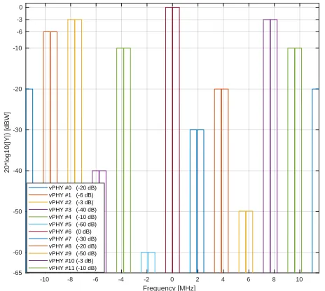
In Figure 10, we show the frequency-domain representation of the wide base-band signal generated by the proposed wire-less hypervisor. Here, in this figure, the hypervisor multiplexes, in the frequency domain, the signals of12vPHYs,M, where each vPHY uses128subcarriers, NvPHY, totalling1536 subcar-riers, which is the number of points used by the IFFT block in the hypervisor, N. Each vPHY only modulates72subcarriers and leaves the remaining subcarriers along its edges as guard-bands. The subcarrier at the center of each vPHY channel is set to 0, which is used to allow receivers to employ simpler/cheap direct-conversion (i.e., zero intermediate-frequency) RF front-end receivers. In the example, shown in the figure, 64QAM
TABLE IV: MSEANDMERFOR SEVERAL DIFFERENT FILTER ORDERS.
Filter Order
16 64 128 256 512 1024
MSE 1.3317e-03 1.9853e-08 3.6452e-09 3.2091e-09 3.8513e-10 2.3038e-10
MER [dB] 5.1897 53.4555 60.8164 61.3699 70.5720 72.8092
-10 -8 -6 -4 -2 0 2 4 6 8 10
Frequency [MHz]
-65 -60 -50 -40 -30 -20 -10 -6 -3 0
20*log10(|Y|) [dBW]
vPHY #0 (-20 dB) vPHY #1 (-6 dB) vPHY #2 (-3 dB) vPHY #3 (-40 dB) vPHY #4 (-10 dB) vPHY #5 (-60 dB) vPHY #6 (0 dB) vPHY #7 (-30 dB) vPHY #8 (-20 dB) vPHY #9 (-50 dB) vPHY #10 (-3 dB) vPHY #11 (-10 dB)
Fig. 11: Closer look at the frequency-domain boost factor.
modulation is used to modulate the data signal. As can be seen, there are (i) a guard-band between consecutive vPHY signals, (ii) a null-subcarrier exactly at the center of each one of the vPHY transmissions, (iii) and different transmission levels for the vPHYs. As shown in the figure, it is possible to give independent gains to each vPHY, which is accomplished by multiplying the NU
vPHY useful modulation symbols by a multiplication factor varying from 0 (no transmission power at all) to1(maximum transmission power used by the physical RF front-end). Figure 11 gives a closer look at the boost factor, showing that it is possible to vary the transmitted power of each individual vPHY just by changing the factor used to multiple the useful subcarriers, NU
vPHY. The legend on the figure shows the attenuation given to the default transmission
20 40 60 80 100 120
Sample number -0.15
-0.1 -0.05 0 0.05 0.1 0.15
Amplitude
Real part
PHY vPHY #1 vPHY #2
20 40 60 80 100 120
Sample number -0.1
-0.05 0 0.05 0.1 0.15
Amplitude
Imaginary part
PHY vPHY #1 vPHY #2
-30 -25 -20 -15 -10 -5 0
SNR [dB]
10-6
10-5
10-4
10-3
10-2
10-1
Uncoded BER
QPSK
vPHY #0 vPHY #1 vPHY #2 vPHY #3 vPHY #4 vPHY #5 vPHY #6 vPHY #7 vPHY #8 vPHY #9 vPHY #10 vPHY #11 Single PHY Theoretical
(a)
-30 -25 -20 -15 -10 -5 0 5 10
SNR [dB]
10-6
10-5
10-4
10-3
10-2
10-1
Uncoded BER
16QAM
vPHY #0 vPHY #1 vPHY #2 vPHY #3 vPHY #4 vPHY #5 vPHY #6 vPHY #7 vPHY #8 vPHY #9 vPHY #10 vPHY #11 Single PHY Theoretical
(b)
-10 -5 0 5 10 15
SNR [dB]
10-6
10-5
10-4
10-3
10-2
10-1
Uncoded BER
64QAM
vPHY #0 vPHY #1 vPHY #2 vPHY #3 vPHY #4 vPHY #5 vPHY #6 vPHY #7 vPHY #8 vPHY #9 vPHY #10 vPHY #11 Single PHY Theoretical
(c)
Fig. 13: BER curves for a setup where12vPHYs concurrently have their signals multiplexed by the hypervisor and use: (a) QPSK, (b)16QAM and (c)
64QAM modulation schemes.
power of a vPHY, which is around 0[dBW] as shown by the vPHY centered around 0[Hz].
Figure 13 presents uncoded BER results for a setup where
12 vPHYs concurrently have their signals multiplexed by the hypervisor and employ QPSK, 16QAM, and64QAM modu-lation schemes. In each one of the sub-figures, we compare the BER for the 12 vPHYs against the BER achieved by a single PHY, i.e., there is no other signal being transmitted along with that of the PHY under test. In this simulation, we consider an Additive White Gaussian Noise (AWGN) channel. The single PHY and each one of the 12vPHYs modulate72
(i.e., NUvPHY) out of 128(i.e., NvPHY) consecutive subcarriers by using a64QAM modulation scheme. The hypervisor’s IFFT length, N, is set to 1536 and the cyclic prefix length, NCP, is set to 108samples. For each SNR point, 1×10⁶iterations
were run, where the total number of wrongly decoded bits and transmitted bits were calculated for the BER calculation. As can be seen, the vPHY BER curves exactly match the single PHY BER curve (dashed black curve with squares along it), meaning that there is no interference between the current transmissions. Additionally, it is also worth mentioning that all curves match the theoretical BER curves (red-dashed curve with dots along it), which can be approximated by (15) [50].
Pb≈
2(√γ−1)
√
γlog2(γ)erfc
s
3 log2(γ)(Eb/N0)
2(γ−1)
!
, (15)
whereγ is the modulation order andEb/N0 is the bit energy
over the power spectrum density. The result presented in Figure 13(c), is very important as it proves that the proposed architecture provides perfect isolation among all the signals being multiplexed. The perfect isolation is due to the orthog-onality provided by the IFFT processing in the hypervisor, which guarantees that every single subcarrier, spaced of ∆f [Hz], is mutually orthogonal to all other ones.
VIII. EXPERIMENTALEVALUATION
In this section, we present some experimental results carried out in order to validate and assess the functionality of the proof of concept implementation of the proposed architecture.
All the experiments presented in this section were carried out with the prototype running on a desktop with an Intel Xeon E5-2650 v4 CPU (@2.2 GHz, 30 M cache, 9.60 GT/s QPI, Turbo, HT, 12 Cores/24 Threads, 105 Watts) with 128 GB of RAM memory connected to a x310 USRP with10Gigabit Ethernet link, and equipped with CBX-120RF daughterboards [51]. These RF daughterboards operate from1200up to6000
MHz with a bandwidth of 120MHz [51].
For all the experiments presented in this section, each vPHY has a useful transmitting BW of1.08MHz, which is equivalent to6 LTE RBs, and a guard-band of420 KHz at each side of the transmitted spectrum, totalling1.92MHz of used BW (i.e., useful-band plus guard-band sections) per vPHY, totalling12× 1.92 MHz/vPHY = 23.04 MHz of occupied BW when we have12vPHYs operating concurrently.
Figure 14 shows the spectrum of 12 vPHYs transmit-ting concurrently. This figure was collected with an Anritsu MS2690A Signal Analyser. The RF front-end center frequency was set to2.4GHz and Tx gain set to3[dB] with the USRP Tx output connected to the signal analyser through a cable with20
[dB] of attenuation. As can be seen, the total transmission BW spans over23.04MHz, which is equivalent to having12 1.92
MHz wide vPHYs with their center frequencies located at1.92
MHz apart from each other. Additionally, we can also see that the two vPHYs transmitting at the right and left edges suffer from attenuation, which is caused by cascaded integrator-comb (CIC) filter roll-off. CIC filter are implemented in the USRP to provide decimation by an arbitrary programmable integer decimation factor, however, they present a very significant pass-band roll-off, which are often called spectral droop or CIC rolloff [52].
Figure 15 shows the spectrogram (time versus frequency) for the same experiment setup used to capture Figure 14. In this experiment all 12 vPHYs transmit in streaming mode,
Fig. 14: Spectrum of12vPHYs concurrently transmitting at a center frequency of2.4GHz.
Fig. 15: Spectrogram of 12 vPHYs concurrently transmitting at a center frequency of2.4GHz.
Figure 16 shows that the proof of concept prototype of the proposed hypervisor is able to handle discontinuous trans-missions and to apply independent gains to each vPHY, as described in Section III. Again, we used the same experiment setup used to capture Figure 14. In this experiment all 12
vPHYs transmit in discontinuous (bursty) mode with random number of subframes transmitted in a row, channel number and frequency amplification factor. The number of subframes, channel number and frequency amplification factor of each vPHY are randomly selected between the ranges0−11,0−5, and 0−100 % respectively. The transmitted signal was cap-tured for a period of100ms. As can be seen, the prototype is also able to work on bursty mode with independent frequency amplification factor for each vPHY. This result also shows
Fig. 16: Spectrogram of 12 vPHYs with discontinuous transmissions and independent frequency gains at a center frequency of2.4GHz.
that the prototype also supports run-time configuration of the number of transmitting vPHYs as we see that not all vPHYs might be transmitting during a period.
The following experiments are executed by adding a channel emulator between the Tx and Rx sides of the prototype. At the Tx side, the generated multiplexed signal, instead of being sent to the USRP HW is sent to an abstraction layer that emulates the HW and adds additive white Gaussian noise (AWGN) to the transmitted signal, next, the abstraction layer transfers the noisy signal to the receiving side of the prototype.
Figure 17 shows the throughput measurements taken with the proposed architecture prototype for several MCS values and a Duty Cycle (DC) of 95.24%. In this experiment, the prototype works in full-duplex mode (i.e., it is simultaneously transmitting and receiving) with1single vPHY (upper part of the figure) and 12vPHYs (lower part of the figure) working at the same time. We adopt a full-duplex mode in order to check if this mode somehow impacts the measured throughout, as in full-duplex mode the prototype is being fully utilised. The measurements were taken with transmissions of 20 ms (i.e., 20 subframes) and a gap of 1 ms between subsequent transmissions, and therefore, a DC of95.24%. The throughput is calculated as an average over10measurement intervals of
0 2 4 6 8 10 12 14 16 18 20 22 24 26 28 MCS
0 1 2 3 4 5
Throughput [Mbps]
Theoretical Single vPHY Tput (DC: 100 %) Experimental Single vPHY Tput (DC: 95.24 %)
0 2 4 6 8 10 12 14 16 18 20 22 24 26 28 MCS
0 10 20 30 40 50 60
Throughput [Mbps]
Theoretical 12 vPHYs Tput (DC: 100 %) Experimental 12 vPHYs Tput (DC: 95.24 %)
Fig. 17: Prototype’s throughput for single and 12 vPHYs over different MCS values.
1 ms. As can be seen, the measured prototype’s throughput approaches the theoretical maximum throughput for all MCS values, yielding more than4.14Mbps in the single vPHY case and more than 49.2 Mbps in the 12 vPHYs case for MCS
28. Additionally, as can be also noticed, the operation in full-duplex mode has no visible impact on the achieved throughput. This is due to the powerful server, with 12 CPU cores, used to run the prototype.
Next, in Figure 18 we compare the data packet reception ratio (PRR) of a single PHY against the data PRR of 12
vPHYs concurrently transmitting over a range of SNR val-ues. In this experiment, 12 vPHYs concurrently have their signals multiplexed, transmitted and received by the prototype. The experiment uses 3 different MCS values so that all 3
modulation schemes employed by LTE standard (i.e., QPSK,
16QAM, and 64QAM) are tested. The PRR is calculated as the average over 105 Monte Carlo trials, where at each
trial, the Tx side of the prototype sends either a single PHY signal or the multiplexed signal of 12 vPHYs. In each one of the sub-figures, we compare the PRR of the 12 vPHYs against the PRR obtained with a single PHY, i.e., there is no other signal being transmitted along with that of the PHY under test. As theorised earlier, the PRR curve of the 12
concurrent transmitting vPHYs match the PRR of the single PHY (i.e., the dashed black curve with squares along it). This means that there is no interference between the current vPHY transmissions. These results prove that the prototype of the proposed architecture also, as showed before with the simulation results, provides isolation among all the signals being multiplexed by the prototype. The achieved isolation is due to the orthogonality provided by the IFFT processing implemented by the prototype.
Figure 19 depicts the CPU and memory utilization of the prototype for several MCS values. These results compare CPU
and memory utilization when the prototype has to multiplex the signal of 1 and 12 vPHYs, respectively. The results in the figure were calculated by averaging CPU and memory usage values sampled every 200 ms during the duration of the experiment, which was set to 60 seconds. Each one of the vPHYs transmit 20subframes in a row with a 1 ms gap between consecutive transmissions.
As can be observed, the CPU utilization increases as the MCS increases, however, there is no CPU starvation issue. The increase in CPU utilization is mainly due to the fact that as the MCS value increases (i.e., higher data rates), the turbo encoding (at Tx side), synchronization and turbo decoding (both at Rx side) processing tasks become more complex and consequently demand a lot more of CPU for data processing. For a MCS equal to28and12vPHYs concurrently transmitting, the CPU utilization is of approximately450 %, meaning that the processing power of fewer than 5 cores is being employed, leaving the other cores in the idle state for large periods. On the other hand, we see that the memory utilization is practically constant for all MCS values and goes from around0.5%to2.2%for1and12vPHYs, respectively. Therefore, memory utilization is practically independent of the MCS value being used. This is an expected result as all memory being used by the prototype is pre-allocated during its initialization. Therefore, based on the results presented in Figure 19, it can be concluded that the prototype does not exhaust CPU or memory resources as the MCS value increases. These are important results, once they show that given the current server configuration, the prototype can be scaled to support even more vPHYs without exhausting CPU or memory resources.
Next, in Figure 20, we present the assessment of the CPU consumption of independent processing tasks making up the architecture prototype. For this assessment we employ the callgrindtool, which is part of thevalgrindprofiler.Callgrind is a profiling tool that keeps the call history among functions in a program’s run as a call-graph through the use of runtime instrumentation [13, 57]. The figure presents the functions with the highest CPU processing load (i.e., the most representative CPU consumers) for 3 different MCS values and the cases where1and12vPHYs are instantiated. The setup used for this experiment is the same as the one used during the experiment for CPU and memory profiling.
As can be noticed, channelization presents the highest CPU consumption throughout all test cases. Channelization is a quite heavy processing once it keeps always processing a bandwidth equivalent to the maximum number of configured vPHYs, which in this case is equal to12, no matter the number of actually instantiated vPHYs. For 1 instantiated vPHY, inverse FFT is the second most consuming task, however, its CPU consumption remains constant for all considered MCS values as it does not depend on the MCS used. In the case that
12vPHYs are instantiated, we see that memory copy,memcpy, increases its load from 15.35% for MCS 0 to approximately
20%for MCS28. Compared to the1vPHY case, it is a drastic increase once it has a maximum CPU load of7.41%for MCS
![Fig. 9: Frequency response of a polyphase filter-bank with stop-band attenu-ation of 180 [dB] and 512 filter coefficients per sub-band.](https://thumb-us.123doks.com/thumbv2/123dok_us/7955349.1319992/11.612.58.295.510.720/frequency-response-polyphase-lter-attenu-ation-lter-coefcients.webp)