ABSTRACT
MACLEOD, MARC. Dynamic Modeling, Analysis, and Testing of a Variable Buoyancy System for Unmanned Multi-Domain Vehicles. (Under the direction of Dr. Matthew Bryant). This paper presents the system design and dynamic model of an active variable buoyancy
system (VBS) actuator with applications to unmanned multi-domain vehicles. Unmanned multi-domain vehicles have a unique concept of operations that require nontraditional VBS
designs. We present a VBS actuator design that focuses on vehicle design objectives of high endurance, stealth, and loitering while underwater. The design consists of an elastic bladder housed within a rigid ballast tank, hydraulic pump, and proportionally controlled vent valve.
Ambient surrounding water is the system working fluid and the elastic bladder serves to separate the gas–water interface, eliminating the risk of the compressed gas escaping when
venting the water during extreme pitch maneuvers. A nonlinear analytic model of the VBS is derived and used to examine the parameter design space and the effects on water flow rate,
actuation force, and energy efficiency. The VBS actuator design is shown to require a smaller, denser energy storage device than a comparable buoyancy system that uses consumable compressed air. A vehicle model is studied that features forward and aft VBS
actuators, which enables vehicle pitch control by shifting the center of gravity along the vehicle’s longitudinal axis. The coupling between the VBS actuator dynamics and vehicle
© Copyright 2015 Marc MacLeod
Dynamic Modeling, Analysis, and Testing of a Variable Buoyancy System for Unmanned Multi-Domain Vehicles
by Marc MacLeod
A thesis submitted to the Graduate Faculty of North Carolina State University
in partial fulfillment of the requirements for the degree of
Master of Science
Mechanical Engineering
Raleigh, North Carolina
2015
APPROVED BY:
_______________________________ _______________________________ Dr. Matthew Bryant Dr. Ashok Gopalarathnam
ACKNOWLEDGMENTS
I gratefully acknowledge funding support from DARPA and Teledyne Scientific Company, without which the present research could not have been completed. I thank my committee members for their support and the rest of my student research team for their help in making this project a success. I also thank iSSRL for providing the lab space and equipment necessary for completion of the project. Finally I thank my advisor Dr. Matthew Bryant for his endless support and guidance, which was critical to this research.
TABLE OF CONTENTS
LIST OF TABLES ... v
LIST OF FIGURES ... vi
1. INTRODUCTION... 1
1.1. Brief Survey of Multi-Domain Vehicle Designs ... 1
1.2. Buoyancy Control for UUVs ... 5
1.3. Proposed VBS Actuator ... 8
2. VARIABLE BUOYANCY SYSTEM MODEL ... 9
2.1. System Configuration ... 9
2.2. Dynamic System Model ... 11
2.3. Variable Buoyancy System Actuator Analysis ... 14
3. MODEL ANALYSIS RESULTS AND DISCUSSION ... 16
4. COMPARISON TO CONSUMABLE COMPRESSED AIR BUOYANCY SYSTEM ... 22
5. HOW TO SIZE THE BALLAST TANK ... 26
6. DYNAMIC VEHICLE SYSTEM MODEL ... 32
6.1. System Configuration ... 32
6.2. Nonlinear System Model ... 34
7. VEHICLE SYSTEM DYNAMIC RESULTS ... 37
8. PROOF-OF-CONCEPT DEMONSTRATION... 41
9. CONCLUSIONS ... 48
LIST OF TABLES
LIST OF FIGURES
Figure 1. VBS ballast tank operating concept... 10 Figure 2. Maximum bidirectional actuation force as a function of vehicle depth limit for tank pressure limits from 5 to 25 bar in 4 bar increments. ... 17 Figure 3. Ballast tank fill fraction limit as a function of vehicle depth for 0.7 ml/rev pump displacement and applied voltages from 12 to 28 volts in 4 volt increments. Results shown for tank precharges [depth limits] of 2.7 bar [15 m], 4.4 bar [30 m] and 7.6 bar [60 m]. ... 18 Figure 4. Ballast tank fill fraction as a function of pump torque for 0.7 ml/rev pump
Figure 14. Vehicle and VBS actuator step response simulation. Step occurs at 0 s with step inputs shown in legend. All vehicle initial conditions set to zero. Step response results shown
for (a) pitch, (b) depth, (c) tank 1 & 2 water volumes, and (d) motor 2 current. ... 40
Figure 15. VBS Demo Platform prototype. ... 41
Figure 16. Elastic bladder inside ballast tank in (a) deflated and (b) inflated states. ... 43
Figure 17. Ballast tank design with precharge port ... 44
Figure 18. Descending maneuver at a nearly fixed pitch by pumping water into the fore and aft ballast tanks. ... 46
Figure 19. Pitch and depth change maneuver by venting the fore ballast tank. ... 47
Figure 20. Extreme pitch maneuvers of (a) 83° pitch up and (b) -56° pitch down. ... 47
1. INTRODUCTION
The concept of a multi-domain unmanned vehicle that can travel through air, land, and/or sea domains is of great interest to the military, aerospace, and marine community. An airplane has unobstructed flight throughout the skies with high speed, high maneuverability,
and high range capabilities. In contrast, a submarine has free range of the waters with high stealth and loitering capabilities. Combining these two vehicle concepts would produce a
submersible aircraft capable of high speed and range through air as well as high stealth and persistence while underwater. A vehicle with these desirable capabilities would enable unique concept of operations that were previously impossible with a single-domain vehicle.
1.1. Brief Survey of Multi-Domain Vehicle Designs
The concept of a multi-domain vehicle has been around for decades. In the 1930s, the first manned flying submarine concept was proposed [1]. Since then there have been other attempts at manned aquatic-aerial domain vehicles but none of these prototypes demonstrated
useful water and air operation [2]. The major design challenge was the added complexity from the vehicle being manned. Compared to an unmanned aquatic-aerial vehicle, a manned
version must be significantly larger to fit a human crew and life support systems. A manned vehicle must also be structurally stronger to support the added loads from the crew, life support systems, and relatively larger payloads.
Much work has been done on aquatic-aerial unmanned vehicle designs. Most of these UAV designs can be categorized into three different types based on their method of launch
seaplane UAV is capable of taking off and landing on the water surface through a
conventional taxiing approach. Since this design is not capable of underwater operation, any loitering or surveillance must be performed while the vehicle floats on the water surface. Several seaplane UAV designs exist in the literature starting from 2002, such as the US
NASA Ames Research Center’s ACAT [3], the DRS RQ-15 Neptune [4], and the Warrior (Aero-Marine) Ltd.’s GULL24 and GULL36 [5]. The submarine-launched UAV has a much
different concept of operations. The submarine-launched UAV is typically stored in the submarine torpedo tube while underwater. When deployed, the UAV is either launched by the torpedo tube or released and allowed to propel itself to the water surface. Upon breaking the
water surface, many designs undergo some degree of morphing to enable aerial flight. For instance, the Sea Sentry [6] by Kollmorgen Corporation has forward and aft wing surfaces
that are folded parallel to the fuselage while the UAV is stored in the submarine’s universal modular mast (UMM). Upon breaking the water surface, the Sea Sentry’s wings rotate 90° into a traditional fixed-wing configuration. Similarly, the Sea-Robin XFC [7] by the U.S.
Navy features a pair of wing structures that are parallel to the fuselage while stored, then rotate into position when transitioning to air flight. Like the seaplane UAV, the
submarine-launched UAV is not designed to operate underwater. It also requires a support vehicle like a submarine for underwater operation.
Compared to the previous two categories of aquatic-aerial vehicles, the submersible UAV design is the fullest-featured design. This UAV is capable of operating underwater, flying in the air, and transitioning between the two domains. Unlike the seaplane UAV, it is able to
support vehicle while underwater. Much of the submersible UAV work in the literature
feature bio-inspired designs. In 2009, Beihang University developed the Flying Fish [2], which was inspired by flying fish, waterfowls, and seaplanes. Their prototype vehicle is able to perform a seaplane taxiing takeoff from the water surface, fly in the air, and land again on
the water surface via seaplane taxiing. The vehicle is also able to submerge by filling a ballast tank with the surrounding ambient water, then propel itself underwater using two
water pumps. During submergence, the wings sweep back to become parallel to the fuselage to minimize drag. One of the key challenges with the submersible UAV is the water entry and water exit transitions. One studied water entry technique is the plunge dive, which is
bio-inspired by the gannet. These birds have long slender bodies and wings that sweep back to minimize impact loads and increase their water penetration depths. They begin their dive
from heights of up to 30 m in the air and plunge into the water at speeds of up to 24 m/s [8]. Several recent studies have been conducted on implementing the plunge dive into a submersible UAV design [9]–[11], but no prototype exists in the literature to date that
demonstrates flight capabilities followed by a survivable plunge dive. The Naval Research Laboratory (NRL) also tested the plunge dive concept with their submersible UAV platform,
Test Sub II [12]. Test Sub II demonstrated gliding aerial flight followed by a water landing via plunge dive or conventional skimming landing. The vehicle was not designed to
For aquatic and terrestrial domain vehicle design, much of the recent work has focused
on bio-inspired swimming/crawling robot designs [13]. The AmphiBot I and II are snake-like robots that use lateral body undulations for propulsion while in water and a crawling technique for locomotion on land [14], [15]. Similarly, the AmphiRobot I and II are also
snake-like robots that use the same body undulation method for water propulsion, but instead use powered wheels while on land [16]. In addition to snake-like robots, legged amphibious
robots designs have also been demonstrated. The AQUA is a robot with six appendages that is capable of both legged and swimming locomotion [17]. The six appendages function as legs for walking while on land and as paddles during swimming.
One of the major challenges of designing a multi-domain vehicle are the unusual vehicle operation requirements. The vehicle must have high durability to survive underwater environments and high reliability during domain transitions, yet be sufficiently lightweight
and maneuverable such that air flight or land locomotion performance is minimally compromised. Many vehicle components or systems have primary functionality in only one
domain, such as wings for air flight or wheels for land locomotion. While operating in the other domains, these inactive systems only increase the required vehicle size and weight, therefore decreasing the vehicle operating range and endurance. Thus, these single-function
1.2. Buoyancy Control for UUVs
A variable buoyancy system (VBS) is a vehicle system functional in only one domain. This system is responsible for regulating the vehicle depth and orientation while operating underwater. In many unmanned underwater vehicles (UUVs), vehicle depth and orientation is
exclusively controlled using the hydrodynamic forces over the vehicle’s control surfaces [18]–[21]. Other UUV designs use thrusters to control vehicle depth and orientation [21],
[22]. Depending on the payload weight, these vehicle designs are sometimes manually trimmed to near neutral buoyancy prior to the start of each mission. Trim techniques include adding weights or adjusting the amount of water in a ballast tank [23]. Similarly, UUV
gliders use control surfaces and hydrodynamic forces for depth control but also internal actuators for attitude control. Gliders commonly control vehicle pitch by shifting an internal
mass and therefore generating a restoring force due to the difference in center of gravity and center of buoyancy locations [24]. The SLOCUM glider [25] can also change the overall vehicle buoyancy during operation through the use of a thermal engine featuring internal and
external bladders. Many UUVs feature an active buoyancy control system that adjusts the vehicle’s total buoyancy throughout the mission [22], [23], [26], [27]. A variable buoyancy
system (VBS) can also be used to exclusively control the vehicle’s depth and orientation. This is advantageous for several reasons. First, there is no need for thrusters for depth or
Lastly, motionless loitering can be performed indefinitely with little to no energy input.
Buoyancy control systems can also be found in nature. A sperm whale is able to control its net buoyancy through a large volume of spermaceti oil in the whale’s head. The whale can heat or cool this oil by passing warm blood or cold seawater around it, causing the volume of
oil to expand or contract slightly. As the volume of oil changes, so does the sperm whale’s buoyancy [28].
Several methods of buoyancy control exist for underwater vehicles. Large manned submarines typically control the net vehicle buoyancy by using a ballast tank, the ambient water pressure, and compressed air. To decrease buoyancy and perform a dive maneuver, the
flood valves of a ballast tank are opened and the ambient water pressure forces water into the tank. Simultaneously, any air inside the ballast tank is pushed out through a vent valve into
the surrounding water, which prevents a buildup of air pressure inside the tank and enables the water to passively fill the ballast tank. With enough water in the ballast tank, the vehicle is able to reach neutral buoyancy. To perform an ascent maneuver, the flood valves are
opened but the air vent valves are closed. Compressed air is then blown into the ballast tanks, forcing water out of the tank through the flood valves [29]. This buoyancy system design
requires a second tank that stores the compressed air as well as an on-board air compressor to recharge the compressed air tank if the mission duration is long enough that the tank cannot
store sufficient air. One potential drawback with this design is that the vehicle must access the water surface to operate the air compressor, which is undesirable if stealth is essential. Some unmanned UUVs similarly use the surrounding ambient water as the working fluid.
perform a dive maneuver [23], [27]. In some designs the air inside the tank is also vented as
water is pumped in [27]. In contrast, other UUVs do not vent the air as water fills the vehicle and instead allow for a pressure buildup in the ballast tank or hull [30]. Other designs commonly use an active method of filling the ballast tank with the use of a water pump [22],
[27], [30]. To increase buoyancy and perform an ascent maneuver, water is pumped out of the ballast tank. Instead of a rigid ballast tank, some UUVs also pump water into an elastic
bladder that is located inside the vehicle hull [30].
Another buoyancy control approach is to use air as the working fluid. As part of the Test Sub II vehicle platform, Young [12] developed a buoyancy system featuring a forward and
aft bladder system to control both depth and pitch. To increase buoyancy, air from the pressure hull is pumped into the bladders, increasing the bladder’s volume and therefore the
overall buoyancy. Air inside the bladders is then vented back into the pressure hull to decrease buoyancy. The major drawback with this design is that the system is inherently unstable in depth and heave velocity due to the compressibility of the working fluid, air. For
instance if the bladders have a fixed amount of air contained in them and an environmental disturbance causes the vehicle to slightly increase depth, the increase in water pressure from
the depth change causes the air inside the bladders to compress. As the bladder air is compressed, the volume displaced by the bladder decreases and so does the buoyancy force.
1.3. Proposed VBS Actuator
The VBS for a multi-domain vehicle has a special set of design requirements due to the vehicle’s unique concept of operations. First, the VBS must be lightweight and compact in order to minimize the additional energy requirement for carrying the inactive VBS through
the other domains. This includes minimizing the energy storage device volume, which may involve powering the VBS by the vehicle’s existing energy source. Minimizing the VBS
volume also frees up space for additional components such as sensors or payload, which may be useful in the air and land domains. Second, the VBS should be able to maintain the vehicle at a desired depth for loitering or surveillance operations. Lastly, the VBS should be
able to perform extreme vehicle pitch angles that orient the vehicle horizontally or vertically. In a water-air domain vehicle, a horizontal orientation may be useful for efficient underwater
locomotion or sensing while loitering. A vertical pitch-down maneuver could enable a streamlined heaving orientation for depth change via buoyancy control only. A vertical pitch-up maneuver could orient the underwater vehicle for an aerial vertical takeoff pitch-upon breaking
the water surface. In a water-land domain vehicle, the same pitch-up maneuver could orient the vehicle for a water-land transition, such as a vertical wall climbing operation.
In this paper, we propose and investigate a VBS design suitable for multi-domain vehicles. The VBS design reflects multi-domain vehicle design objectives of high endurance,
Sec. 4, we compare the VBS design to a consumable compressed air buoyancy system in
terms of energy per actuation and energy storage device volume. In Sec. 5, we discuss a methodology for sizing the VBS design based on the vehicle parameters. In Sec. 8, a proof-of-concept demonstration is presented and compared to the vehicle model-predicted results.
2. VARIABLE BUOYANCY SYSTEM MODEL
2.1. System Configuration
Ambient water from the surroundings is chosen as the VBS working fluid because of the ability to eject all working fluid prior to flight or land operations. Compared to VBS designs
that use air and an on-board compressor, a water pump based VBS design does not need to resurface occasionally to recharge compressed air tanks. A VBS design that vents air also creates underwater air bubbles that are visible from the water surface especially in shallow
waters, decreasing stealth. A rigid ballast tank concept was chosen to eliminate the system instabilities associated with using air and an external elastic bladder like in Young’s design
[12], which enhances loitering capabilities via less complicated controls and energy consumption. Furthermore, a battery powered VBS concept is chosen over a compressed air tank system due to electric batteries having a greater energy storage device density (see Sec.
4), resulting in a more compact VBS design.
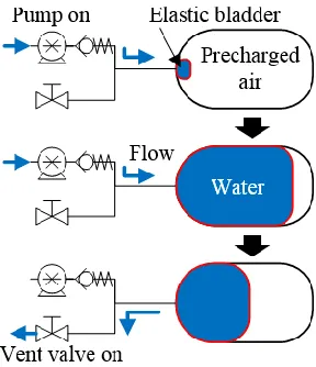
Our proposed VBS ballast tank design consists of a rigid ballast tank with an inner elastic
surrounding ambient water into the ballast tank and the elastic bladder, compressing the air inside the tank. A check valve downstream from the pump eliminates leakage through the
pump due to backpressure. To increase vehicle buoyancy or perform an ascent maneuver, a proportional servo vent valve is opened and the water is forced out from the ballast tank due
to the potential energy stored in the compressed air. The elastic bladder ensures that no air accidently escapes during the venting operation regardless of the vehicle orientation.
Figure 1. VBS ballast tank operating concept
Pre-pressurizing or precharging the air inside the tank is necessary so that the air pressure is
always greater than the surrounding ambient water pressure, which is dependent on the vehicle’s instantaneous depth. The vent valve operation relies on a positive pressure
powering a zero-power-hold on/off vent valve or a low power proportional solenoid vent valve uses less energy than powering a water pump to actively remove water from the tank.
2.2. Dynamic System Model
In order to investigate the relationship between control inputs and the VBS actuator force
output, we begin by modeling the fluid dynamics for a single ballast tank. Due to the incompressibility of water, the system can be modeled using mass continuity and Bernoulli’s equation for a streamline running from the pump outlet to inside the ballast tank. The
dynamic hydraulic system equation is expressed as
𝑃𝑜+𝜌
2(
𝑉̇𝑤 𝐴𝑝)
2
= 𝑃𝑔 (1)
where 𝑃𝑜 is fluid pressure at pump outlet, 𝜌 is density of water, 𝑉̇𝑤 is the fluid’s volumetric
flow rate, 𝐴𝑝 is cross-sectional area of the tubing at the pump outlet, and 𝑃𝑔 and is pressure of
the air inside the tank. Losses through the check valve, hydraulic tubing, and elastic bladder
are assumed to be negligible. For the tubing and tank sizes used in the proof-of-concept prototype in Sec. 7, the tank fluid velocity is only about 0.2% of the tubing fluid velocity and therefore the tank fluid velocity is neglected. Assuming that the air compression process
occurs over a relatively long period of time, the process can be approximated by the isothermal relation
𝑃𝑔 = 𝑃𝑔,0𝑉𝑡
where 𝑃𝑔,0 is initial air pressure inside the tank, 𝑉𝑡 is total volume of the ballast tank, and 𝑉𝑤
is volume of water inside the tank. The initial air pressure inside the tank is function of the
operation depth limit according to
𝑃𝑔,0 = 𝜎(𝑃𝑎𝑡𝑚+ 𝜌𝑔𝑍𝑚𝑎𝑥) (3)
where 𝑃𝑎𝑡𝑚 is atmospheric pressure, 𝑍𝑚𝑎𝑥is the vehicle’s operational depth limit, 𝑔 is
gravitational acceleration, and 𝜎 is a safety factor to ensure that the tank air pressure is
always greater than the ambient water pressure.
The ballast tank and vent valve opening form a nozzle with an inlet and outlet area equal
to the cross-sectional area of the tank and the cross-sectional area of the vent valve opening, respectively. The flow rate through this vent valve nozzle can also be modeled using mass continuity and Bernoulli’s equation [8]. For a streamline running from inside the ballast tank
to the vent valve outlet and taking positive flow to be into the tank, the fluid volumetric flow rate is expressed as
𝑉̇𝑤 = −𝜅𝐴𝑡√2𝜂(𝑃𝑔 − 𝑃𝑧)
𝜌(1 − 𝜅2) (4)
𝜅 =𝐴𝑣
𝐴𝑡 (5)
where 𝜂 is nozzle efficiency, 𝐴𝑣 is cross-sectional area of the vent valve opening, 𝐴𝑡 is
cross-sectional area of the ballast tank, and 𝑃𝑧 is surrounding ambient water pressure. The ambient
The pump and motor system models are developed next. The required input torque for the constant displacement pump is expressed as
𝜏 =𝛿(Δ𝑃)
2𝜋 (6)
Δ𝑃 = 𝑃𝑜− 𝑃𝑧 =
𝑃𝑔,0𝑉𝑡
𝑉𝑡− 𝑉𝑤− 𝜌 2( 𝑉̇𝑤 𝐴𝑝) 2
− (𝑃𝑎𝑡𝑚 + 𝜌𝑔𝑍) (7)
𝑉̇𝑤 =
𝛿𝜔𝜇
2𝜋 (8)
where 𝛿 is the pump’s fixed volumetric displacement per revolution, 𝑍 is vehicle depth, 𝑉̇𝑤 is
volumetric flow rate assuming a positive displacement pump, 𝜔 is pump shaft rotational
speed, and 𝜇 is volumetric efficiency, which is a function of the pump outlet pressure [31].
The pump is assumed to be powered by a DC electric motor, whose dynamic model is
expressed as 𝜔̇ =𝐾𝑒𝑖 − 𝐵𝑣𝜔 − 𝜏 𝐽 (9) 𝑑𝑖 𝑑𝑡= −𝑖𝑅 − 𝐾𝑏𝜔 + 𝐸 𝐿 (10)
where 𝐾𝑒 and 𝐾𝑏 are torque and speed constants, 𝐵𝑣 is viscous damping coefficient, 𝐽 is
combined moment of inertia of motor armature and pump load, 𝑅 is motor resistance, 𝐿 is
motor inductance, 𝑖 is current, and 𝐸 is applied voltage. The complete state equation for the
volumetric flow rate is determined by combining (4) and (8) resulting in
𝑉̇𝑤 =𝛿𝜔𝜇
2𝜋 − 𝜅𝐴𝑡√
2𝜂(𝑃𝑔− 𝑃𝑧)
While the VBS is actuating, either the pump or the vent valve is operating; they will never be active simultaneously. Both the pump and vent valve can be inactive simultaneously, such as
if the vehicle is loitering. Furthermore the pump can only operate in one direction such that
𝜔 ≥ 0. Thus the relation for water volumetric flow rate can be divided on the basis of three
different operating conditions of applied voltage and vent valve ratio control inputs according
to
𝑉̇𝑤 =
{
0 𝑓𝑜𝑟 𝐸 = 0 𝜅 = 0
𝛿𝜔𝜇
2𝜋 𝑓𝑜𝑟 𝐸 > 0 𝜅 = 0
−𝜅𝐴𝑡√
2𝜂(𝑃𝑔− 𝑃𝑧)
𝜌(1 − 𝜅2) 𝑓𝑜𝑟 𝐸 = 0 𝜅 > 0
(12)
2.3. Variable Buoyancy System Actuator Analysis
With a dynamic system model for the VBS now defined, we consider modeling the
actuation force, energy consumption, and system efficiency of the complete buoyancy system. The actuation force is dependent on the volume of the ballast tank and the water volume limit. If the same actuation force is desired in both the positive and negative heave
directions, then the maximum bidirectional actuation force is expressed as
𝐹𝑚𝑎𝑥 =𝑉𝑤,𝑚𝑎𝑥
2 𝜌𝑔 (13)
where 𝑉𝑤,𝑚𝑎𝑥 is maximum water volume able to be pumped into the tank, which is limited by
the pressure rating of the tank or the stall torque of the pump motor. When the vehicle is at
precharge, and tank volume. The water volume limit nondimensionalized by the ballast tank
volume is determined by rearranging (6), (9), (11) and solving for the motor stall condition
(𝜃̇ = 0 and 𝑖 = 𝑉/𝑅) resulting in
(𝑉𝑤
𝑉𝑡)𝑙𝑖𝑚 = 1 −
𝑃𝑔,0
2𝜋𝐾𝑒𝐸
𝑅𝛿 + 𝑃𝑎𝑡𝑚 + 𝜌𝑔𝑍
(14)
The instantaneous system efficiency during pump operation can be defined as the ratio of tank fluid output power to electrical input power as
𝛽 =𝑃𝑓𝑙𝑜𝑤
𝑃𝑒𝑙𝑒𝑐 =
𝑉𝑤̇ (𝑃𝑔− 𝑃𝑎𝑡𝑚)
𝐸𝑖 (15)
The instantaneous system efficiency accounts for the losses in motor, pump, and hydraulic tubing network, although in this analysis we assume the pump and tubing losses to be
negligible. The average system efficiency across the pump operating range is determined by integrating the instantaneous system efficiency with respect to tank fill fraction according to
𝛽̅ = 1
ℎ𝑙𝑖𝑚∫ 𝛽
ℎ𝑙𝑖𝑚
0
𝑑ℎ (16)
ℎ =𝑉𝑤
𝑉𝑡 (17)
The integral of 𝑃𝑓𝑙𝑜𝑤 with respect to time is equal to the fluid energy produced, 𝑊𝑓𝑙𝑜𝑤. For
comparison purposes, we consider the energy required to compress air, an ideal gas, from
initial volume 𝑉𝑡 to final volume (𝑉𝑡− 𝑉𝑤). Assuming an isothermal process, the energy
required by the system to compress the air is expressed as
𝑊𝑔𝑎𝑠 = −𝑃𝑔,0𝑉𝑡𝑙𝑛𝑉𝑡− 𝑉𝑤
When the hydraulic tubing losses are assumed to be negligible, 𝑊𝑔𝑎𝑠= 𝑊𝑓𝑙𝑜𝑤.
3. MODEL ANALYSIS RESULTS AND DISCUSSION
The VBS actuator model presented above is applied to a notional VBS actuator design.
The motor parameters are for the Maxon brushed DC motor, model number 110124 [32]. The pump is assumed to be lossless and have an output pressure limited only by the stall torque of
the motor. The baseline parameters for the system used throughout the parameter variation study are listed in Table 1. The ballast tank precharge pressure is directly related to the vehicle’s depth limit by (3) and therefore the terms tank precharge pressure and depth limit
are used interchangeably. All reported pressures are absolute units unless otherwise noted.
Table 1. Baseline parameters of the VBS Actuator
Parameter Symbol Value Units
Tubing cross-sectional area 𝐴𝑝 5.7 mm2 Vent valve nozzle efficiency 𝜂 0.9 Unitless Motor and pump inertia 𝐽 8.4 g cm2
Motor inductance 𝐿 0.89 mH
Motor resistance 𝑅 13.8 Ω
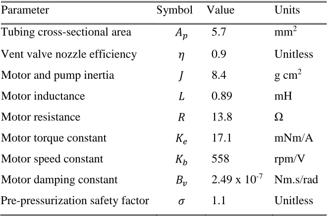
Figure 2 plots the maximum bidirectional actuation force as a function of ballast tank
volume, vehicle depth limit, and tank pressure limit. The tank pressure limit is either the pressure rating of the tank or the maximum achievable pressure due to the pump motor stall characteristics. As the tank pressure limit increases for a fixed tank volume, the maximum
actuation force increases since more water volume can be forced into the tank. The maximum actuation force shows decreasing sensitivity to the tank pressure limit as the limit is
increased. This is because asymptotically increasing energy is required to compress the fixed mass of air inside the tank as its volume approaches zero. Maximum actuation force and vehicle depth limit are inversely proportional for a given ballast tank and tank pressure limit.
Increasing the vehicle depth limit by increasing the tank precharge results in the pump motor reaching stall with less water inside the ballast tank, therefore decreasing the maximum
actuation force.
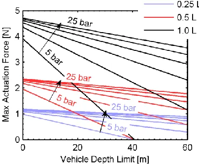
Figure 3 plots the relationship between ballast tank fill fraction limit, precharge pressure,
and applied voltage for a fixed pump displacement according to (14). The tank fill fraction limit dependence on depth is most prominent at lower voltages and higher tank precharges. Depending on the applied voltage and tank precharge, the ambient water pressure is nearly
constant across the vehicle’s operating depth range. In the remainder of this analysis, the ambient water pressure is assumed to be constant at atmospheric pressure in order to
eliminate any required assumptions about the vehicle’s depth change rate and instead focus the analysis on the actuator itself.
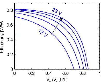
Figure 3. Ballast tank fill fraction limit as a function of vehicle depth for 0.7 ml/rev pump displacement and applied voltages from 12 to 28 volts in 4 volt increments. Results shown for tank precharges [depth limits] of 2.7 bar [15 m], 4.4 bar [30 m] and 7.6 bar [60 m].
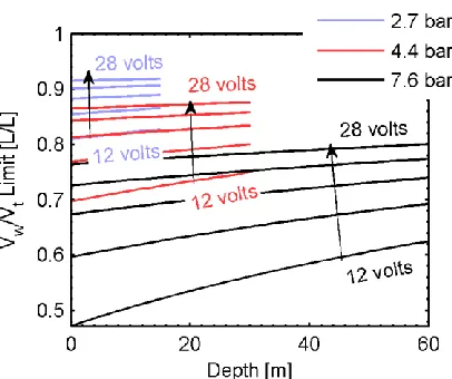
nondimensionalized by the motor stall torque, which is dependent on the applied voltage.
Increasing the tank precharge pressure shifts the tank fill fraction curves to the right because pump torque is proportional to precharge pressure according to (6).
Figure 4. Ballast tank fill fraction as a function of pump torque for 0.7 ml/rev pump displacement and applied voltages from 12 to 28 volts in 4 volt increments. Results shown for tank precharges [depth limits] of 4.4 bar [30 m] and 7.6 bar [60 m].
During a system command to increase net buoyancy, the control input is the vent valve
nozzle area ratio, 𝜅. In Figure 5, we examine the effect of the nozzle area ratio on the rate of
water exiting the ballast tank. The tank is assumed to have an initial fill fraction of 0.8 and a depth limit of 30 m. Next the vent valve is opened and the water is forced out of the tank by
the internal compressed air. Tank emptying time shows decreasing sensitivity to nozzle area ratio as the ratio is increased. For instance, the decrease in emptying times from nozzle area
Figure 5. Ballast tank vent operation time for 4.4 bar precharge pressure and vent valve nozzle area ratios from 5 x 10⁻⁵ to 3 x 10⁻⁴ in increments of 5 x 10⁻⁵.
The effect of applied voltage and pump displacement on system efficiency is plotted in
Figure 6 and Figure 7. As applied voltage increases, instantaneous system efficiency increases across the tank fill fraction range because the motor is able to operate closer to its
peak efficiency torque-speed operating point, which occurs at a high rotational speed. An optimal pump displacement is also apparent for maximum efficiency. For the range of pump displacements investigated, a pump displacement of 0.01 ml/rev is optimal if the tank is
primarily operated between fill fractions of 0.4 – 0.8. This optimal pump displacement again corresponds to the motor operating most closely to its peak efficiency torque-speed operating
point. As pump displacement is increased or decreased from this optimum, the motor speed is decreased or increased and the motor operates farther from its peak efficiency torque-speed
Figure 6. Instantaneous system efficiency for pump displacement of 0.7 ml/rev, 4.4 bar precharge pressure, and various applied step voltages.
4. COMPARISON TO CONSUMABLE COMPRESSED AIR BUOYANCY SYSTEM
For comparison purposes, we consider a consumable compressed air buoyancy system
(CABS) in terms of energy storage device volume. Unlike the VBS which uses a battery as the main energy storage device, a CABS uses a tank of high pressure compressed air to
convert the potential energy stored in the compressed air into mechanical work. In this analysis we consider each system to have the same ballast tank water volume limit and therefore the same maximum bidirectional actuation force. For the CABS, the water volume
limit is equal to the ballast tank volume because the tank is able to be completely filled with water. This is not true for the VBS because the ballast tank volume is equal to the water
volume limit plus a volume of captive air. The additional VBS ballast tank volume is
expressed as (𝑉𝑡− 𝑉𝑤,𝑚𝑎𝑥) and is considered a part of the total VBS energy storage device
volume because the captive air provides the energy for the venting operation. The VBS design uses one motor, pump, and vent valve per ballast tank while the CABS design uses three valves per ballast tank. These three valves include an air vent valve, a water flood
valve, and a valve to the compressed air source. The volume of the VBS motor/pump combination is estimated to be roughly equivalent to the volume of the two extra CABS
valves, resulting in both systems having comparable component volumes. Furthermore, both systems are approximated to only consume energy during either an ascent or descent cycle. The CABS only consumes compressed air energy during ascent maneuvers and although
maneuvers and any energy consumed for valve actuation is assumed to be comparatively negligible.
To compare the energy storage device volumes of the VBS and CABS, we begin by determining the ideal energy consumption of the CABS to complete a specified
descend/ascend cycle. We assume that the vehicle is initially on the water surface with the ballast tank empty. Next the vehicle fills the ballast tank to the water volume limit and begins the dive maneuver. Upon reaching the set cycle depth, the vehicle initiates the ascent
maneuver by expelling all water from the tank and returns to the starting position at the water surface. The mass of compressed air required to expel all water from the ballast tank for the
CABS as a function of depth can be determined from the ideal gas law according to
𝑚𝑎𝑖𝑟 =
𝑃𝑔,0𝑉𝑡
𝑅𝑎𝑖𝑟𝑇 (19)
where 𝑅𝑎𝑖𝑟 is the specific gas constant of air and 𝑇 is the temperature of the air. This mass of
air must be blown into the ballast tank to initiate every ascent cycle. The amount of energy in
this mass of air available to do work is equal to (𝑃𝑔,0− 𝑃𝑎𝑡𝑚)𝑉𝑡. From the ideal gas law, the
CABS compressed air tank volume is expressed as
𝑉𝑠,𝐶𝐴𝐵𝑆 =𝑁𝑚𝑎𝑖𝑟𝑅𝑎𝑖𝑟𝑇
𝑃𝐶𝐴𝐵𝑆− 𝑃𝑔,0 (20)
where 𝑁 the number of cycles and 𝑃𝐶𝐴𝐵𝑆 is the pressure limit of the compressed air tank. At
the end of the last cycle, the compressed air tank pressure is equal to the required ballast tank air pressure per cycle. Therefore at the start of the of the last cycle, a positive pressure
the VBS energy storage device is equal to the volume of the battery plus the volume of the additional ballast tank volume according to
𝑉𝑠,𝑉𝐵𝑆 = 𝑁𝑊𝑔𝑎𝑠
𝛽̅ϵ + 𝑉𝑡− 𝑉𝑤,𝑚𝑎𝑥 (21)
where 𝛽̅ is average system efficiency across the ballast tank fill fraction range and 𝜖 is
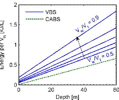
battery volumetric energy density. The battery energy density was taken to be 1.2 MJ/L based on a survey of typical commercially available Li-Po batteries [33]. Figure 8 plots the
ideal energy consumed per cycle comparison. It is expected that the CABS energy per cycle is lower because there is no asymptotic increase in ballast tank backpressure as the CABS blows air into the ballast tank. As the VBS ballast tank fill fraction approaches zero, the VBS
curve approaches the CABS curve because the captive air backpressure is lower at smaller
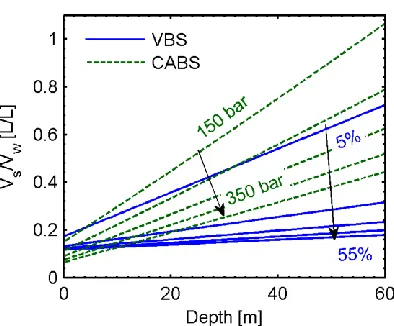
tank fill fractions. Figure 9 plots the energy storage device volume comparison for 𝑁 = 20 and shows that depending on the compressed air tank pressure limit and the vehicle depth
limit, even a relatively inefficient VBS is able to match the required energy storage device volume of the CABS. For instance, if the max pressure rating of the compressed air tank is
350 bar and the vehicle depth limit is greater than 30 m, then an overall VBS energy efficiency of only 15% is necessary for a smaller energy storage device volume compared to
the compressed air tank of the CABS. From Figure 6, Figure 7, and (16), average system efficiencies of up to 72% are possible depending on the motor, pump displacement, and applied voltage. Furthermore, a max pressure rating of 350 bar is on the high end for
Table 2. Typical commercially available compressed air tank specifications
Tank Type Volume [L] Weight [kg] Pressure [bar] Paintball compressed air tank, carbon fiber [34] 0.7 – 1.5 0.80 – 1.3 207 – 310 Scuba diving tank, aluminum [35] 0.9 – 13.2 1.2 – 18.6 207 – 228 Scuba diving tank, composite [35] 11.1 15.3 300
5. HOW TO SIZE THE BALLAST TANK
This section presents a methodology on how to design the VBS ballast tank. This methodology is for a single ballast tank but can be extended to include multiple tanks. The
procedure is also for obtaining an equal bidirectional actuation force but can be modified if different actuation forces are desired for the positive and negative heave directions. To begin
sizing the ballast tank, we first consider the vehicle parameters prior to adding the VBS system. To bring the vehicle to neutral buoyancy, the VBS must offset the vehicle’s existing buoyancy force resulting in zero net force acting on the vehicle. The net force acting on the
vehicle with the VBS is determined by
𝐹𝑛𝑒𝑡 = 𝑊0+ 𝑊𝑉𝐵𝑆 + 𝜌𝑉𝑤𝑔 − (𝐵0+ 𝐵𝑉𝐵𝑆+ 𝐵𝑡) (22)
where 𝑊0 and 𝐵0 is the total vehicle weight and buoyancy prior to adding the VBS and 𝑊𝑉𝐵𝑆
is the total dry weight of the VBS which includes the weight of the tank, motor, pump,
valves, ballast tank, hydraulic plumbing, and additional components. The buoyancy force
from the external VBS ballast tank is 𝐵𝑡 and the buoyancy force from any additional external
VBS components is 𝐵𝑉𝐵𝑆. If the ballast tank and any additional VBS components are
packaged inside the existing vehicle hull or dry payload bay, then 𝐵𝑡 and 𝐵𝑉𝐵𝑆 would be
zero. The ballast tank buoyancy force is related to the ballast tank size by the relationship 𝐵𝑡 = 𝜌𝑉𝑡𝑔, where 𝑉𝑡 is the volume of the ballast tank. Equation (22) shows that if the ballast
tank is empty of water and if the sum of the total VBS buoyancy force and total dry weight is
positive (𝐵𝑉𝐵𝑆+ 𝐵𝑡+ 𝑊𝑉𝐵𝑆 > 0), then the sum of the initial vehicle buoyancy force and
total dry weight must be negative (𝐵0+ 𝑊0 < 0). In other words, the net buoyancy of the
vehicle prior to adding the VBS must be negative if the net buoyancy of the VBS addition is
positive. If the VBS is added externally to the existing vehicle, then the buoyancy contributions of the VBS ballast tank and additional components can be rewritten in terms of water displacement volumes and grouped into a single water volume displacement term
resulting in
𝑉0,𝑁𝐵 = 𝑉𝑡− 𝑉𝑤+ 𝑉𝑉𝐵𝑆 (23)
where 𝑉𝑉𝐵𝑆 is the volume of the VBS components not packaged inside the existing vehicle.
The term 𝑉0,𝑁𝐵 represents the volume of water displacement required to bring the existing
vehicle with no VBS to neutral buoyancy. To determine 𝑉0,𝑁𝐵 based on vehicle parameters,
we multiply both sides of equation (23) by 𝜌𝑔 to turn the volumes into buoyancy forces,
𝑉0,𝑁𝐵 = 𝑊0+ 𝑊𝑉𝐵𝑆− 𝐵0
𝜌𝑔 (24)
Thus the required volume of water displacement from the VBS is dependent on the initial dry weight of the vehicle, weight of the VBS, and the initial buoyancy force of the vehicle. To
study the relationship between 𝑉0,𝑁𝐵 and the size of the ballast tank we examine the case
where 𝑉𝑉𝐵𝑆 is negligible, resulting in 𝑉0,𝑁𝐵 = 𝑉𝑡− 𝑉𝑤. Another constraint on this ballast tank
sizing procedure is that an equal bidirectional actuation force is desired in both the positive
and negative heave directions. As a result the ballast tank must be sized such that neutral
buoyancy is achieved when the tank is filled to half of its water volume limit, or 𝑉𝑤 =
𝑉𝑤,𝑚𝑎𝑥⁄2. When the water volume limit is present inside the ballast tank, the volume of
captive air is at its minimum. This air volume is determined by the isothermal gas
compression assumption according to
𝑉𝑔,𝑓 =𝑃𝑔,0𝑉𝑡
𝑃𝑔,𝑓 (25)
where 𝑃𝑔,𝑓 is the tank pressure limit. The water volume limit able to be pumped into the tank
must be determined when the vehicle is at zero depth. If the water volume limit was
determined when the vehicle was at a specific depth, then the resulting maximum actuation force could only be reached at that specific depth due to the ambient water pressure aiding
the motor and pump. With these constraints, the volume of water displacement required to bring the existing vehicle to neutral buoyancy can be now determined. Figure 10 shows a
The size of the ballast tank can be modeled as a function of the water volume limit and
minimum captive air volume according to equation (25), resulting in
𝑉𝑡= 𝑉𝑤,𝑚𝑎𝑥+
𝑃𝑔,0𝑉𝑡
𝑃𝑔,𝑓 (26)
Thus, the ballast tank size is a function of the water volume limit, initial precharge pressure,
and the tank pressure limit. Due to the desired equal bidirectional actuation force constraint, another ballast tank sizing relationship shown in Figure 10 is
𝑉0,𝑁𝐵 =
𝑉𝑤,𝑚𝑎𝑥
2 +
𝑃𝑔,0𝑉𝑡
𝑃𝑔,𝑓 (27)
Equations (26) and (27) form a system of equations that describe the required ballast tank size. For this tank sizing design problem, it is more convenient to investigate the max
bidirectional actuation force rather than the max water volume. After replacing 𝑉𝑤,𝑚𝑎𝑥 with
𝐹𝑚𝑎𝑥 according to equation (13), the new system of equations describing the required ballast
tank size is
𝑉𝑡 =
2𝐹𝑚𝑎𝑥
𝜌𝑔 +
𝑃𝑔,0𝑉𝑡 𝑃𝑔,𝑓
𝑉0,𝑁𝐵 =
𝐹𝑚𝑎𝑥
𝜌𝑔 +
𝑃𝑔,0𝑉𝑡
𝑃𝑔,𝑓 (28)
𝑉0,𝑁𝐵 is a known parameter based on the vehicle parameters. From the solution to the system
of equations, the max bidirectional actuation force can be expressed as a function of the
ballast tank size and 𝑉0,𝑁𝐵 according to
𝐹𝑚𝑎𝑥 = 𝜌𝑔(𝑉𝑡− 𝑉0,𝑁𝐵) (29)
This equation is independent of the pressure ratio. Therefore if two of the design parameters (𝐹𝑚𝑎𝑥, 𝑉𝑡, 𝑉0,𝑁𝐵) are known or selected, then the third parameter is automatically determined.
Based on the constraint that 𝑉𝑉𝐵𝑆 is negligible, the tank volume is constrained to be greater
than or equal to the neutral buoyancy volume (𝑉𝑡 > 𝑉0,𝑁𝐵). The neutral buoyancy volume
must also be greater than half of the tank volume, or (𝑉𝑡< 2𝑉0,𝑁𝐵), based on the constraint
for an equal bidirectional actuation force. If the latter equality is violated, then the vehicle
would not be at neutral buoyancy when 𝑉𝑤 = 𝑉𝑤,𝑚𝑎𝑥⁄2 based on Figure 10. For any valid
combination of 𝐹𝑚𝑎𝑥, 𝑉𝑡, and 𝑉0,𝑁𝐵 that satisfies equation (29) or shown in Figure 11(a), a
specific pressure ratio is required based on the system of equations in (28). Figure 11(b) plots the required pressure ratio as a function of the neutral buoyancy volume and ballast tank
(a) (b)
Figure 11. Relationship between neutral buoyancy volume, ballast tank volume, (a) max bidirectional actuation force, and (b) pressure ratio.
A 𝑃𝑔,𝑓/𝑃𝑔,0 pressure ratio of unity means that the max achievable tank pressure is equal to the
initial precharge pressure. As a result, no water can be pumped into the tank and therefore the
max actuation force is zero. For this special case the required ballast tank size is simply equal to the required water displacement volume for neutral buoyancy. As the pressure ratio
increases from unity, asymptotic behavior is observed in Figure 11(b) as the constraint 𝑉𝑡 <
2𝑉0,𝑁𝐵 is approached. This is due to the asymptotically increasing energy required for
compressing the air inside the ballast tank as the air volume approaches zero.
From Figure 11, the complete relationship between neutral buoyancy volume, ballast tank
volume, max actuation force, and pressure ratio can be determined. For instance, for a
specific 𝑉0,𝑁𝐵 based on vehicle parameters and desired 𝐹𝑚𝑎𝑥, the required tank volume and
required pressure ratio can be determined. Or, for a specific 𝑉0,𝑁𝐵 and selected pressure ratio,
be made between tank size and max actuation force. Minimizing the ballast tank volume has
the advantage of minimizing the required pressure ratio, reducing the pressure loads on the ballast tank resulting in a more lightweight and compact ballast tank. However, minimizing the tank size limits the max actuation force, resulting in limited vehicle depth and pitch
control rates. On the other hand, maximizing the max actuation force results in a larger required tank size and higher required pressure ratio. A high pressure ratio means high
pressure loads on the ballast tank, resulting in an undesirable heavier ballast tank design due to the large structural loads.
6. DYNAMIC VEHICLE SYSTEM MODEL
6.1. System Configuration
To examine the coupling between the VBS actuator and vehicle dynamics, a notional
underwater vehicle is modeled. The simplified vehicle model consists of two VBS actuators located forward and aft to enable depth and pitch control. For modeling purposes each set of
motor, pump, and vent valve assembly are lumped into single point masses and point buoyancies. The complete vehicle is then modeled as a system of six point masses and six point buoyancies. The point buoyancy location for each component is assumed to be
(a)
(b)
Figure 12. Notional vehicle setup with VBS. Schematic shown for (a) coordinate system, and (b) point mass/buoyancy approximations. All dimensions in mm, not drawn to scale.
Table 3. VBS Test Platform II component approximations
Component Symbol Mass [kg] Buoyancy [N] Ballast tank 1, dry 𝑇1 0.065 2.45 Ballast tank 2, dry 𝑇2 0.065 2.45 Motor, pump, valve assembly 1 𝑃1 0.380 1.02 Motor, pump, valve assembly 2 𝑃2 0.380 1.02 Electronics enclosure 𝐸𝑒 0.650 10.3
The vehicle’s center of buoyancy (CB) location is determined by a buoyancy force balance in
the x and z directions according to
𝑥𝑐𝑏 =𝑉1𝑥1+ 𝑉2𝑥2+ ⋯ + 𝑉𝑛𝑥𝑛
𝑉1+ 𝑉2+ ⋯ + 𝑉𝑛 (30)
where 𝑉𝑛 and 𝑥𝑛 is water displacing volume and x-location of the 𝑛th component relative to
the trailing edge of the aft ballast tank. The same procedure is used to determine the CB
z-location. The vehicle CB location is fixed and therefore the body-fixed coordinate system origin is chosen to be coincident with the CB. The vehicle center of gravity (CG) is determined by a force balance according to
𝑥𝑐𝑔 =
𝑥1(𝑚1+ 𝜌𝑉𝑤,1) + 𝑥2(𝑚2+ 𝜌𝑉𝑤,2) + 𝑚3𝑥3+ ⋯ + 𝑚𝑛𝑥𝑛
𝑚1+ 𝜌𝑉𝑤,1+ 𝑚2+ 𝜌𝑉𝑤,2+ 𝑚3+ ⋯ + 𝑚𝑛 (31)
where 𝑚𝑛and 𝑥𝑛 are mass and x-location of the 𝑛th component relative to the CB and 𝜌𝑉𝑤,𝑛
is the mass of the water in the 𝑛th ballast tank. The mass of water in each tank is modeled as
coincident with the ballast tank point mass locations.
6.2. Nonlinear System Model
Throughout the literature [36]–[38], generalized underwater vehicle’s dynamic equations of motion can be described by
𝑴𝑣̇ + 𝑪𝑣 + 𝑫𝑣 + 𝐺 = 𝜏𝑓 (32)
where 𝑴 is sum of the inertia and added mass matrices, 𝑪 is sum of the rigid-body and
hydrodynamic Coriolis and centripetal matrices, 𝑫 is damping matrix, 𝐺 is restoring force
by varying its buoyancy and assuming no water currents, the external force vector is zero. Considering only motion in the longitudinal plane, the velocity and position vectors reduce to
𝑣 = [𝑢, 𝑤, 𝑞]𝑇 (33)
𝜂 = [𝑋, 𝑍, 𝜃]𝑇 (34)
where 𝑣 is expressed with coordinates in the body-fixed frame and 𝜂 is expressed with
coordinates in the earth-fixed frame (see Figure 12).
To estimate the added mass and damping terms, the vehicle shape was approximated as a prolate ellipsoid whose major and minor axes correspond to the vehicle’s length (𝑙 = 0.68 m)
and width (𝑑 = 0.1 m), respectively. The body inertia matrix is modeled from rigid-body Newton-Euler equations and is dependent on the vehicle’s total mass, moment of
inertia, and CG location [37], [38]. For a vehicle with three planes of body symmetry and operating at low speeds, the added mass matrix is simplified to a diagonal structure [36], [37]. The added mass terms for a prolate ellipsoid are described by Fossen [37].
The normal and axial force coefficients are described by Jorgensen [39] as
𝐶𝑁=
𝐴𝑝
𝐴𝑟𝐶𝑑𝑛sin
2𝛼 (35)
𝐶𝐴 = 𝐶𝐴𝑜cos2𝛼 (36)
where 𝛼 is the angle of attack, 𝐴𝑝 is the planform area, 𝐴𝑟 is the reference area, 𝐶𝑑𝑛 is the
crossflow drag coefficient (𝐶𝑑𝑛 ≈ 1.2, 𝑅𝑒 < 3 𝑥 105[39]), and 𝐶𝐴𝑜 is the axial drag
coefficient at zero angle of attack (𝐶𝐴𝑜= 0.25 [40]). For a vehicle traveling at speed 𝑈, the
𝐹𝑁=
𝐶𝑁𝜌𝑈2𝐴 𝑟
2 (37)
𝐹𝐴 =
𝐶𝐴𝜌𝑈2𝐴 𝑟
2 (38)
The viscous damping moment is calculated by integrating the damping force on a
differential area of the ellipsoid (see Figure 13) at a position (𝑎 − 1)𝑙 ≤ 𝑟 ≤ 𝑎𝑙 relative to
the CG location along the major axis according to
𝑀𝑞 =1
2𝜌𝐶𝐷,𝑞∫ 𝑑𝑑|𝑣|𝑣
𝑎𝑙
(𝑎−1)𝑙
𝑟𝑑𝑟 (39)
where the upper and lower limits of integration represent the leading and trailing edges of the ellipsoid along its major axis [41].
Figure 13. Diagram for computing the viscous damping moment.
Based on drag coefficients for two-dimensional circular bodies given by Cengel and Cimbala
[40], 𝐶𝐷,𝑞 is 1.2. The CG location along the ellipsoid major axis is located a distance 𝑎𝑙 from
the trailing edge, where 𝑎 is a dimensionless parameter such that 𝑎 = 1 corresponds to the
leading edge, and 𝑎 = 0 corresponds to the trailing edge. The variable 𝑣 is the local velocity
𝑣 = −𝑤 + (𝑟 + 𝑥𝑐𝑔)𝑞 (40) where 𝑤 and 𝑥𝑐𝑔 are defined with respect to the CB x-location and 𝑟 is with respect to the
CG x-location. The variable 𝑑𝑑 is the width of the differential segment and is a function of the location along the ellipsoid’s major axis according to
𝑑𝑑 = 𝑑√|1 − (
2𝑟
𝑙 )
2
| (41)
The restoring force vector is expressed as
𝐺 = [
(𝑊 − 𝐵)sin (𝜃) −(𝑊 − 𝐵)cos (𝜃)
(𝑧𝑐𝑔𝑊 − 𝑧𝑐𝑏𝐵) sin(𝜃) + (𝑥𝑐𝑔𝑊 − 𝑥𝑐𝑏𝐵)cos (𝜃)
] (42)
where 𝑊 is total weight of the vehicle and 𝐵 is total buoyancy force. The VBS actuator and
vehicle dynamics are coupled through the mass matrix and CG terms 𝑥𝑐𝑔 and 𝑧𝑐𝑔. The
vehicle nonlinear dynamics are then expressed as
[ 𝑢̇ 𝑤̇
𝑞̇] = −𝑴
−1𝑪 [
𝑢 𝑤 𝑞] − 𝑴 −1[ 𝐹𝐴 𝐹𝑁 𝑀𝑞
] − 𝑴−1𝐺 (43)
𝑋̇ = 𝑢 cos 𝜃 + 𝑤 sin 𝜃 (44)
𝑍̇ = −𝑢 sin 𝜃 + 𝑤 cos 𝜃 (45)
𝜃̇ = 𝑞 (46)
7. VEHICLE SYSTEM DYNAMIC RESULTS
initial pitch angle of -7.6°. This pitch angle corresponds to the statically stable orientation of the vehicle due to the difference in the initial CG and CB locations. Both ballast tanks have
an initial ballast tank fill fraction of 0.4. Each tank has a precharge pressure of 4.4 bar and therefore the vehicle depth limit is 30 m. The first step response, shown in blue, represents a
pitch change only maneuver. A 18 V step input is sent to the forward pump motor and a step
input of 𝜅 = 7.8 𝑥 10−5is sent to the aft vent valve, causing the CG to shift forward and the
vehicle to pitch downward. Once the motor has reached the stall current, the applied voltage is removed and the current goes to zero. The steady-state value of the ballast tank water volumes shows the tank 1 fill fraction limit is 0.8 while the tank 2 fill fraction is zero,
resulting in the vehicle being neutrally buoyant and the net force on the vehicle in the heave direction to be zero. During the transient response of the ballast tank water volumes, the
water flow rates for tank 1 and 2 are slightly different and therefore the vehicle is not neutrally buoyant at all times. As a result, the vehicle depth fluctuates slightly about zero in Figure 14(b). The second step response, shown in black, represents a pitch and depth change
maneuver. The only input is a 12 V step input to the forward pump motor. The water level in tank 1 remains constant throughout the simulation. In comparison to the pitch change only
maneuver, the magnitude of the steady-state vehicle pitch result is much smaller. This is expected because not emptying the water from tank 1 results in the CG shifting less forward.
The third step response, shown in red, represents a depth change only maneuver. Both pump motors receive a 14 V step input and thus the forward and aft ballast tanks fill with water at the same rate. The steady-state pitch response is not zero because the two ballast tanks are
step response pumps water into the ballast tank(s) at a slower rate than in the third step response, the second step response achieves a faster heave velocity. The pitch change in the
second step response orients the vehicle into a more streamlined position for heaving with less drag. The implication from this result is that a vehicle energy efficiency advantage exists
with extreme pitch control. In the second response, only one motor is active and operated at a lower voltage and current, resulting in a much lower system energy consumption than in the third response.
The step response results show the vehicle stability with the presented VBS actuator design. For all three initial step inputs, the vehicle reaches a stable, constant terminal
velocity. This is in contrast to a VBS design using an external air bladder, which does not reach a stable vehicle velocity in response to a step input. This inherent stability reduces the complexity of adding a controller if an autopilot or closed-loop depth and pitch regulation is
(a) (b)
(c) (d)
8. PROOF-OF-CONCEPT DEMONSTRATION
The VBS Demo Platform proof-of-concept was constructed to demonstrate the VBS
actuator design and vehicle depth and pitch control (see Figure 15). The overall vehicle length is 0.64 m and the max body width is 0.1 m. The total dry mass is 1.3 kg and the total
buoyancy is 16.7 N. The vehicle features two ballast tanks and a single motor and pump combination. The hydraulic tubing cross-sectional area is the same as that listed in Table 1. The volume of each ballast tank is 250 ml. The motor is powered by a 3 cell Li-Po, 2100
mAh battery and is controlled through a radio transmitter operating at 72 Mhz.
Figure 15. VBS Demo Platform prototype.
The motor and pump are hobby RC components intended for hydraulic oil applications. The
motor is a brushless DC motor connected to a 50 A electronic speed controller (ESC). The pump is a mini hydraulic oil pump intended for use with hobby RC oil hydraulic actuators
and has a max pressure specification of 80 bar. For oil pumps of this scale, 80 bar is very high and therefore questionable because of its low cost design. However, since the max operating pressures in our application are only about 8 bar, no testing of the pump’s claimed
instead of hydraulic fluid during operation. Nonetheless, it is important that the pump is cycled using hydraulic oil following any operation with water to force any residual water out
of the pump chambers. If any residual water is allowed to sit for even just a few hours, the working fluid is noticeable rust-filled during the next operation. One somewhat unexpected
result is that the motor and pump are able to operate underwater with no additional waterproofing needed. One caveat is that if the motors are not completely dried or sprayed with WD-40 following submergence testing, the residual water can cause minor rusting on
the bearing sleeves and races. This rust has not caused any noticeable performance issues to date.
A servo-actuated spool valve assembly directs which tank is connected to the pump and therefore only one tank can be pumped at a time. Each tank is connected to its own vent valve, which consists of another servo-actuated spool valve assembly. The waterproof servos
used are the Hi-Tec HS-5086WP. Compared to traditional non-waterproof servos, the selection of COTS waterproof servos is limited. Waterproofing techniques exist for
traditional COTS non-waterproof servos, which increases the selection of servos to choose from. Ultimately for our application the COTS waterproof servos met our specifications and eliminated the hassles associated with servo waterproofing. The servos were connected to the
wiring setup using the Molex Mizu-P25 lineup of waterproof electrical connectors.
The battery, RC receiver, and ESC are all stored inside the watertight electrical enclosure.
if the antenna wire was kept inside the electrical enclosure. A 2.4 GHz transmitter and receiver were also tested, but communication was unsuccessful when submerged under a
couple feet of water. The higher frequency signal experienced much greater attenuation by the water than 72 MHz.
Each ballast tank is a 250 ml HDPE lab bottle and although these bottles are not designed to hold pressure, burst tests experiments showed that they could withstand pressures up to 100 – 120 psi, which is more than sufficient for our proof-of-concept vehicle. Burst tests also
showed that the failure mode is typically due to material elongation followed by rupture along the flash lines from the blow molding process. In an effort to increase the burst
pressure of the bottles, fiber reinforced strapping tape is wrapped around the bottle diameter. However, no further burst test experiments were conducted to test the new burst pressure of the reinforced bottles. A pressure relief valve is also connected to each ballast tank to reduce
the likelihood of bursting. The elastic bladder inside the ballast tank is a high-quality latex balloon. Figure 16 shows the bladder in its deflated and inflated states.
(a) (b)
For the VBS Demo Platform, precharging the captive air inside the ballast tanks was unnecessary because the max vehicle depth was only 11 ft, which was the max depth of the
pool used for testing. Ballast tank designs with the ability to add precharge were also investigated and shown in Figure 17. A second thru-wall fitting is installed in the tank and
acts as the precharge port. A check valve on the precharge port ensures that the precharge pressure cannot escape. To vent the precharge pressure, either the check valve is removed or the bottle cap is loosened. Although a globe or ball valve in place of the check valve would
enable easier precharge venting, a check valve was chosen due to the weight advantage and because the need to vent the precharge pressure was uncommon.
Figure 17. Ballast tank design with precharge port
One issue during operation is the presence of air in the hydraulic lines and bladder. Upon initially placing the dry vehicle in water and running the VBS to perform a dive maneuver, the residual air that is present in the hydraulic lines and bladder becomes trapped by the
incoming pumped water. This is an inherent issue for any VBS system that uses pumps and water as the working fluid. However, initially running the VBS through a series of pumping
and venting cycles mitigates this issue. In our experiments, one or two pumping and venting Check valve
Air precharge port Hydraulic
cycles was sufficient to bleed the air from the hydraulic lines, as evidenced by the disappearance of air bubbles during venting cycles.
Proof-of-concept testing was performed at the Carmichael Aquatic Center at North Carolina State University. The vehicle was manually controlled with an RC transmitter. With
human-in-the-loop control, the vehicle demonstrated maneuvers including pitch control, depth regulation at a fixed pitch, and loitering at a constant depth. A waterproof HD video camera operating at 60 frames per second was mounted to the pool floor and used to record
the vehicle location and orientation during testing. The videos were post-processed frame by frame to determine the vehicle depth and pitch angle as functions of time. Figure 18 and
Figure 19 show video frames from a nearly fixed-pitch depth change maneuver and a pitch and depth change maneuver, respectively. The vehicle is able to descend while remaining approximately horizontally pitched by running the motor steady and frequently diverting the
flow from one ballast tank to the other. For the pitch and depth change maneuver in Figure 19, the vehicle was initially loitering at a constant depth at neutral buoyancy. The vent valve
on the fore ballast tank was then opened, causing the vehicle to pitch up and start ascending. Figure 20 shows the extreme pitch angle capabilities of the vehicle.
The analytical model presented in the preceding section was applied to match the
parameters of the VBS Demo Platform and three unknown parameters were empirically determined for the experiment apparatus. The ballast tank water volumes required for neutral
model-predicted results to the experimental results, which are shown in Figure 21. Likewise, the vent valve nozzle efficiency parameter was determined by fitting the model-predicted
results to the experimental results, resulting in a value of 0.10. This nozzle efficiency value is reasonable because it represents the total flow efficiency going from the ballast tank bladder
to the exit of the spool valve, which is the greatest source of flow inefficiency. All other terms in the model were calculated using the methods presented in Sec. 5. The pitch response results are in close agreement and the depth response results show reasonable overall
agreement. At 5 s, the depth response error is about 23%. It is expected that this error could be reduced with improved modeling or experimental characterization of the added mass and
drag terms to better reflect the body geometry of the VBS Demo Platform.