Effect of Tool Geometry and Process Parameters on
Microstructure and Mechanical Properties of Friction
Stir Spot Welded 2024-T3 Aluminum Alloy Sheets
Memduh Kurtulmuş
School of Applied Sciences, Marmara University, Goztepe Campus, 34722 Kadikoy, Istanbul, Turkey; e-mail address: [email protected] , Fax: +90 216 337 89 87
Abstract: Aluminum alloy Al 2024-T3 were successfully joined using friction stir spot jwelding joining (FSSW). Satisfactory joint strengths were obtained at different welding parameters (tool rotational speed, tool plunge depth, dwell time) and tool pin profile (straight cylindrical, triangular and tapered cylindrical). Resulting joints were welded with welded zone. The different tools significantly influenced the evolution on the stir zone in the welds. Lap-shear tests were carried out to find the weld strength. Weld cross section appearance observations were also done. The macrostructure shows that the welding parameters have a determinant effect on the weld strength (x: the nugget thickness, y: the thickness of the upper sheet and SZ: stir zone). The main fracture mode was pull out fracture modes in the tensile shear test of joints. The results of tensile shear tests showed that the tensile-shear load increased with increasing rotational speed in the shoulder penetration depth of 0.2 mm. Failure joints were obrerved in the weld high shoulder penetration depth and insufficient tool rotation.
Keywords: Pin geometry; friction stir spot welding; mechanical properties; aluminum alloy
1. Introduction
Solid state welding methods, such as, friction stir welding (FSW) and friction stir spot welding (FSSW), are now considered promising methods to join similar and dissimilar materials owing to lower processing temperatures compared to conventional fusion welding. This can avoid the defects associated with fusion welding, which suppresses a blow hole, cracking, and large brittle intermetallic compounds, which results in a degradation of the mechanical properties of the joints [3-6]. Research on butt joints fabricated by friction stir welding to join Al alloys to Cu, Mg, Ti alloys, steel and Mg alloys to Ti alloys have been reported [7,8], however, studies on the lap joints fabricated by FSSW have rarely been carried out. Friction stir spot welding (FSSW) is solid state welding process which fuse materials together by friction heat. The research is associated in friction based process has considerably popular in the last few years. This in fact, can be explained by various advantages of these processes when compared to the conventional fusion welding process.
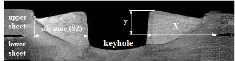
Based on the observations of the FSSW macrostructures, the weld zone of a FSSW joint is schematically illustrated in Figure 1. From the appearance of the weld cross section, three particular points can be identified [9]. The first point is the thickness of the weld nugget (x) which is an indicator of the weld bond area. The weld bond area increases with the nugget thickness. The second point is the thickness of the upper sheet under the shoulder indentation (y). The third point of the stir zone (SZ). The size of these mentioned points determine the strength of a FSSW joint [10]. There are numerous papers concerning about the FSSW parameters which affect the joint geometry and the weld strength [11-13].
Figure 1. Schematic illustration of the cross section of a friction stir spot weld. x: nugget thickness, y: the thickness of the upper sheet and SZ: stir zone.
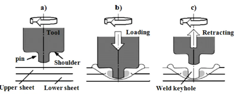
2a and 2b. When the tool reaches the predetermined depth, the plunge motion ends and the stirring phase starts. In this phase, the tool rotates in the workpieces without plunging. Frictional heat is generated in the plunging and the stirring phase and, thus, the material adjacent to the tool is heated and softened. The softened upper and lower workpiece materials mix together in the stirring phase. The shoulder of the tool creates a compressional stress on the softened material. A solid-state joint is formed in the stirring phase. When a predetermined bonding is obtained, the process stops and the tool is retracted from the workpieces. The resulting weld has a characteristic keyhole in the middle of the joint as shown in Figure 2c.
Figure 2. A schematic illustration of the FSSWprocess: (a) plunging; (b) bonding; (c) drawing out.
In this regard, FSSW is expected to produce sound lap joints with satisfactory strength as applicable, when friction stir spot welding has been adopted to join similar and dissimilar materials. Therefore, the present study is the attempt to perform friction stir spot lap joining of aluminum alloy Al 2024-T3 analyze the effects of the welding parameters. The feasibility of joint formation of Al 2024-T3 using friction stir spot joining are examined in terms of mechanical and the metallurgical characteristics.
2. Experiments
were used to fabricate the joints ( Fig. 4 ). Each tool has a 2.4 mm pin length , 5 mm pin size, 14 mm shoulder diameters and 8˚ shoulder concave angle. In straight cylindrical and triangular pins, the pin size was determined by measuring the bottom diameter of the pin. In triangular pin, the pin size was determined by calculating the diameter of the cross section area that was formed by the turning pin. In order to develop the friction stir spot welding tests, a properly designed clamping fixture was utilized to fix the specimens ( Fig. 5 ). The steel plates comprising the fixture ensure a uniform pressure distribution on the fixed specimens. The specimens were welded in a milling machine [14].
In order to obtain sound welded joints, the friction stir spot welding was carried out and compared using different tool rotation speeds, pin geometry and a plunge depth. The friction stir spot welding of Al 2024-T3 is examined in terms of mechanical and the metallurgical characteristics.
Table 1. Mechanical properties and Chemical composition of aluminum alloy. Mechanical properties of 2024-T3 aluminum alloy
Alloy Ultimate tensile (MPa) Yield strength (MPa) Elongation (%)
2024-T3 450 322 15
Chemical composition of 2024-T3 aluminum alloy (Wt.%)
Alloy Al Cu Fe Mg Mn Si Ti Zn 2024-T3 base 4.9 0.239 1.28 0.629 0.0848 0.0154 0.142
Figure 4. FSSW tool profile, a) Straight cylindrical, b) Triangular.
Figure 5. FSSW experimental process [14].
Fig. 3 illustrates the dimensions of the tensile shear test specimens used according to JIS Z 3136 [15] standard to investigate the spot friction welds under the tensile-shear test. The tensile shear tests were performed at room temperature by using an Instron machine with a cross-head speed of 50 mm/min. After welding, the specimens were polished and then etched by a Keller’s reagent for 40s. In addition, the scanning electron microscope equipped the optical microscope were utilized to determine the microstructure and macrostructure of welds.
3. Results
3.1 Macrostructure of welds
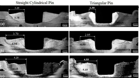
cylindrical and triangular pin had a stir zone (SZ) which was formed in vicinity of the keyhole. SZ changed with different pin geometries and tool rotational speeds. This ocur due to the various flows of materials by different pin geometry.
From the cross sectional view of the joints, it was found that the interface of the joints was soundly joined without any cracks or voids under all studied conditions of tool rotation speed and different pin geometry. Since the sectional area of the triangular pin was less than the cylindrical pin, therefore, a smaller SZ was formed at rotational speeds of 650 and 1000 rpm by the triangular pin. In addition, since the volume of the cylindrical pin was more than the triangular pin, the amount of materials extruded upward was more which resulted in the increase of SZ area and consequently resulted in the increase of the tensile-shear load. The presence of threads on the cylindrical pin enhanced flow and mixing of materials which made increase in the area and width of stir zone. The shape of stir zone at 1600 rpm tool rotational speed was independent of the pin geometry (see Fig. 5c). SZ width was defined as the distance between the edge of the keyhole and the widest region of SZ [13].
Figure 6. Macrostructures of welds made in shoulder plunge depth of 0.2 mm with cylindrical and triangular pin at rotational speed of, (a) 650 rpm, (b) 1000 rpm and (c)1500
rpm.
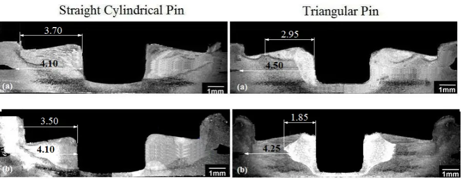
plunge deth led to increase of vertical pressure [16] and consequently spread stir zone area. It is well known that increasing shoulder penetration depth and rotational speed contribute to the increase of stir zone which affect the mechanical properties of welds. When the shoulder penetration continues, the thickness of the upper sheet gets too thin underneath part of the shoulder indentation and therefore the tensile-shear load decreases. Moreover, with increasing rotational speed of both pins, the thickness of the upper sheet became thin beneath the shoulder indentation. Therefore, it should be noted that shape and width of stir zone and also the thickness of the upper sheet were changed based on the welding parameters. Also, the results indicated that the shape and area of stir zone at high rotational speed were independent of the pin geometry (see Fig. 6 c).
Figure 7. Macrostructures of welds made at 1000 rpm tool rotational speed as pin geometry and shoulder plunge depth, (a) 0.2 mm (b) 0.6 mm.
3.2 Tensile shear test
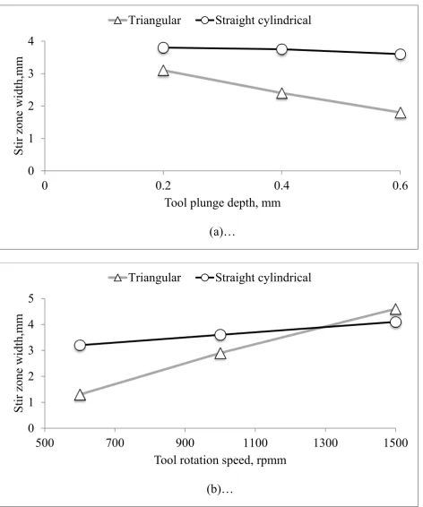
Figure 8. Effect of the tool plunge depth (a) and tool rotation speed (b) on the stir zone width.
Figure 9 shows the tensile shear strength of the joints fabricated under the above mentioned tool rotation speed. In all the welds, the plunge rate was 2.0 mm/s, the tool rotation speed was beetwen 650 and 1500 rpm and the tool plunge depth was from 0.2 to 0.6 mm. The
0
1
2
3
4
0
0.2
0.4
0.6
Stir zone
width,m
m
Tool plunge depth, mm
(a)…
Triangular
Straight cylindrical
0
1
2
3
4
5
500
700
900
1100
1300
1500
Stir zone
width,m
m
Tool rotation speed, rpmm
(b)…
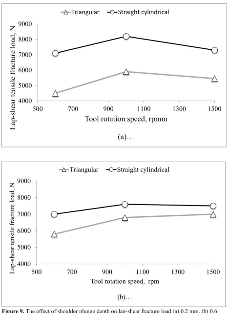
tensile shear strength of the joints was analyzed in terms of tool plunge depth and a reduction in the thickness of the upper side. The highest fracture load (8200 N) was obtained by the straight cylindrical pin at the rotational speed of 1000 rpm and shoulder penetration depth of 0.2 mm. In the same experimental conditions, fracture load was obtained 7300 N (plunge depth (0.6 mm and tool rotation speed 1500 rpm) for the triangular pin. On the other hand, the results revealed that the strength increased with an increase in the tool plunge depth from 0.2 mm to 0.6 mm, however, the strength decreased under the conditions of a tool plunge depth of more than 0.2 mm. Under these conditions, the maximum value of 8200 N for the tensile shear strength of the joints occurred for a tool plunge depth of 0.2 mm.
Figure 9. The effect of shoulder plunge depth on lap-shear fracture load (a) 0.2 mm, (b) 0.6 mm.
4000
5000
6000
7000
8000
9000
500
700
900
1100
1300
1500
Lap-shear tensile fracture load, N
Tool rotation speed, rpmm
(a)…
Triangular
Straight cylindrical
4000
5000
6000
7000
8000
9000
500
700
900
1100
1300
1500
Lap-shear tensile fracture load, N
Tool rotation speed, rpm
(b)…
Furthermore, these results indicated that the tensile-shear load was independent of the pin geometry at the high tool rotational speed and low shoulder penetration depth. In general, for welding 2024-T3 aluminum alloy, the increase of the tool penetration depth and rotational speed were beneficial for increasing tensile-shear load, but the excessive penetration and tool rotational speed impaired the joint properties. Therefore, it was necessary to select a suitable shoulder penetration depth and rotational speed to improve the tensile-shear load and there was an optimal value for rotational speed and shoulder plunge depth.
3.3 Microstructure of welds
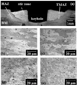
Figure 10 illustrates, the macro and microstructures of different regions in the friction stir spot welding at the rotational speed of 1000 rpm, tool plunge depth of 0.2 mm and straight cylindrical pin. The cross section of the spot friction welds was divided into four regions: stir zone (SZ), thermo-mechanically affected zone (TMAZ), heat affected zone (HAZ), base material (BM) which is shown in Figs. 10 b, c, d and e. The macro and microstructures revealed a maximum tensile shear strength. According to the results presented in Fig. 9, the microstructure in SZ was equiaxed and had very fine grain structure that it can be attributed to the dynamic recrystalization. Since heat affected zone (HAZ) is affected in the frictional heat, the structure of HAZ was like base metal. Grains are elongated because of TMAZ seriously deformed.These structures can be attributed to the vigorous deformation of materials in the TMAZ. As shown in Fig. 10 c and d the grains of the SZ were slightly finer due to the dynamic recrystallization caused by the mechanical force and heat. The microstructure of HAZ was slightly coarser, but a very similar structure to the base metal, which induces a lower hardness value for HAZ.
Figure 10. Effect of tool rotational speed of 1000 rpm and shoulder penetration depth of 0.2 mm with cylindrical pin on the joint section (a) Macrostructure of the joint cross-section and microstructures of (b) BM, (c) HAZ, (d) TMAZ, (e) SZ.
Figure 10 and 11 illustrates that because of the asymmetric rotation of the triangular pin which led to an increase in the material flow, a finger grain structure was formed in the vicinity of the keyhole as the cylindrical pin compared it with the made welds. Meanwhile, the increase of the tool rotational speed led to the generation of the coarser grain size structure in SZ of both pins that it can be attributed to the higher frictional heat generation by higher rotational speeds. Based on these results, the grain size structure in SZ at the high rotational speed was independent of the pin geometry.
4. Conclusions
In this research, the effect of tool geometry and process parameters on microstructure and mechanical Pproperties of Ffiction stir spot welding of the 1,6 mm-thick-AA 2024-T3 was investigated. The following conclusions were made:The pin geometry considerably effected on stir zone shape, stir zone width, nugget thickness in welds.
• With increasing rotational speed, the lap shear tensile fracture load increased, but the shoulder penetration depth had bilateral effects on the lap shear tensile fracture load, which means that, by increasing shoulder penetration depth, the tensile-shear load at first increased and then decreased.
• Regardless of the pin geometry, the increasing shoulder penetration depth and rotational speed caused a decrease in the thickness of the upper sheet beneath the shoulder indentation.
• The shoulder penetration depth had a strong effect on the the lap shear tensile fracture load; with increasing penetration depth, the lap shear tensile fracture load was more concentrated toward the base metal away from the keyhole.
•
References
1. Hancock, R. Friction welding of aluminium cuts energy cost by 99%.; Weld. J. 83, 2004. 40.
2. Khan, M.I., Kuntz, M.L., Su, P., Gerlich, A., North, T., Zhou, Y. Resistance and friction stir spot welding of DP 600: A comparative study; Sci. Technol. Weld. Joining. 12, 2007, 175-182.
4. Nandan, R., DebRoy, T., Bhadeshia, H.K. Recent advances in friction-stir welding -Process, weldment structure and properties; Progress in Mater. Sci. 53, 2008, 980-1023.
5. Pathak, N., Bandyopadhyay, K., Sarangi, M., Panda, S.K. Microstructure and mechanical performance of friction stir spot- welded aluminum-5754 sheets;. J.
Mater. Eng. Perform. 22, 2012, 131-144.
6. Zhang, Z., Yang, X., , Zhang, J., Zhou, G., Xu, X., Zou, R. Effect of welding parameters on microstructure and mechanical properties of friction stir spot welded 5052 aluminum alloy; Mater. Des. 32, 2011, 4462-4470.
7. Lin P. C., Pan J., Pan T. Failure modes and fatigue life estimations of spot friction welds in lap-shear specimens of aluminium 6111-T4 sheets. Part 2: Welds made by a flat tool;
Inter. J. Fatigue, 30, 2008, 90-105.
8. Yang, Q., Mironov, S, Sato, Y.S, Okamoto, K. Microstructure and mechanical properties of friction stir spot welded AZ31 Mg alloy; Proc. 7th Inter. Symposium of Friction Stir Welding, Awaji Island, Japan, TWI. 2008.
9. Gerlich, A., North, T.H. Yamamoto, M. Local melting and cracking in Al 7075-T6 and Al 2024-T3 friction stir spot welds; Sci. Technol. Weld. Joining, 12, 2007, 472-480 .
10. Mishra, R.S., Ma, Z.Y. Friction stir welding and processing; Mater. Sci. Eng, 50, 2005, 1–78.
11. Su, P., Gerlich, A., North, T.H. Friction stir spot welding of aluminum and magnesium alloys sheets; SAE Technical Paper, 01, 2005, 1255.
12. Badarinarayan, H., Shi, Y., Li, X., Okamoto, K. Effect of tool geometry on hook forrmation and static strength of friction stir spot welded aluminum 5754-O sheets; J. Mac. Tool. Manuf, 49, 2007, 814-823.
13. Bozkurt, Y., Uzun, H., Salman, S. Microstructure and mechanical properties of friction stir welded particulate reinforced AA2124/SiC/25p–T4 composite, Journal of Composite Materials, 45, 2011, 2237-2245.
14. Bilici, M.K., Bakır, B., Bozkurt, Y., Çalış, İ. Taguchi analysis of dissimilar aluminum sheets joined by friction stir spot welding, Pamukkale University Journal of Engineering Sciences, 22(1), 2016, 17-23.
17. Wang, D.A., Chao, C.W., Lin, P.C., Uan, J.Y. Mechanical characterization of friction stir spot micro welds; J. Mater. Proc. Technol, 14, 2010, 1942–1948.

![Figure 5. FSSW experimental process [14].](https://thumb-us.123doks.com/thumbv2/123dok_us/8002343.1329369/5.595.154.457.269.460/figure-fssw-experimental-process.webp)