Direct Numerical Simulation of the turbulent flow around a
NACA 0012 airfoil at different angles of attack
A. Baez∗, O. Lehmkuhl∗∗, I. Rodríguez∗and C. D. Pérez-Segarra∗ Corresponding author: [email protected]
∗
Centre Tecnològic de Transferència de Calor (CTTC), Universitat Politècnica de Catalunya, Spain.
∗∗
Termo Fluids S.L.
Abstract: Direct numerical simulations (DNS) of the flow dynamics over a NACA
0012 airfoil at Reynolds number Re=5×10⁴ at different angles of attack are
pre-sented. The dynamic of the large separation bubble, characterised by laminar bound-ary layer separation, transition to turbulence and flow reattachment is analysed in detail by means of instantaneous data al different locations in the suction side of the airfoil. It is found that LSB behaviour is characterised by a low-frequency with a time scale much larger than of the vortex shedding. Thus, in order to capture all the time scales of the flow, statistical results presented have been integrated during a sufficient long time.
Keywords: Computational Fluid Dynamics, Turbulence, Parallelisation, airfoils
1
Introduction
Flows around aerodynamic shapes at low-to-moderate Reynolds numbers have a complex nature known as large separation bubble (LSB) [1] characterised by boundary layer separation, flow transition to tur-bulence in the initially laminar boundary layer, flow reattachment and unsteady shedding of vortices. All these phenomena affect directly the airfoil efficiency, in particular the recirculation bubble formed as a consequence of the separation and reattachment to the airfoil surface. Experimental and numerical stud-ies at high angles of attack (AOA) [2] show the presence of a low-frequency periodic flow phenomena related with the LSB reattachment point. Similar low-frequencies and LSB were experimentally ob-served for a SD7003 airfoil [3]. In the case of NACA 0012, flow regimes with a characteristic Reynolds number of 105 have been recently computed at low AOA [4, 5] but the low-frequency phenomena was not reported.
The advances in computational fluid dynamics together with the increasing capacity of parallel com-puters have made possible to tackle such complex turbulent problems by using high performance numer-ical techniques such as direct numernumer-ical simulation (DNS) and the development of modelling techniques such as Large-Eddy Simulation (LES) methods. DNS has a key role for improving the understanding of the turbulence phenomena and for the simulation of transitional flows in complex geometries, but it is still limited to low and moderate Reynolds numbers [6, 5, 4]. In the present work DNS techniques have been used to study the LSB phenomena on a NACA 0012 airfoil at moderate Reynolds number of Re=5×10⁴, based on the free-stream velocity and the chord length. In the case of flow around
the NACA 0012 airfoil at this Reynold number, flow transition to turbulence undergoes in the initially laminar shear layer. After separation, the turbulent flow reattaches to the airfoil surface forming a bubble which directly affects the airfoil efficiency. The greater the separation bubble, the higher the loss of lift and the increase of drag. Thus, the study of the separation mechanism and the correct prediction of the location of boundary layer transition are both key aspects for improving engineering designs.
Considering this, the present work aims to study the mechanism of shear-layer transition by means of DNS at two AOA 5◦ and 8◦. Main features of the flow, including power spectra of a set of selected monitoring probes at different positions in the suction side and in the near-wake of the airfoil are dis-cussed in detail. These monitoring probes have allowed capturing the main frequencies associated with the LSB. In addition, the capabilities of the parallel methodology used, which require high performance computing and efficient algorithms for accurate solving the flow are also discussed in detail.
2
Mathematical and numerical model
The Navier-Stokes and continuity equations can be written as
Mu = 0 (1)
∂u
∂t +C(u)u+νDu+ρ
−1Gp = 0 (2)
where u∈R3m and p∈Rm are the velocity vector and pressure, respectively (here m applies for the
total number of control volumes (CV) of the discretised domain),νis the kinematic viscosity andρthe density. Convective and diffusive operators in the momentum equation for the velocity field are given byC(u) = (u·∇)∈R3m×3m
, D=−∇2∈R3m×3m
respectively. Gradient and divergence (of a vector) operators are given byG=∇∈R3m×mandM=∇· ∈Rm×3mrespectively.
The governing equations have been discretised on a collocated unstructured grid arrangement by means of second-order spectro-consistent schemes [see 7]. Such schemes are conservative, i.e. they preserve the kinetic energy equation. These conservation properties are held if, and only if the dis-crete convective operator is skew-symmetric (Cc(uc) =−Cc∗(uc)), the negative conjugate transpose
of the discrete gradient operator is exactly equal to the divergence operator (−(ΩcGc)∗=Mc) and the
diffusive operatorDc, is symmetric and positive-definite (the sub-index c holds for the cell-centred
dis-cretisation). These properties ensure both, stability and conservation of the kinetic-energy balance even at high Reynolds numbers and with coarse grids. For the temporal discretisation of the momentum equation (2) a fully explicit second-order Adams-Bashford scheme has been used for the convective and diffusive terms, while for the pressure gradient term an implicit first-order scheme has been used.
The velocity-pressure coupling has been solved by means of a classical fractional step projection method, ucp=un+c 1+Gp˜c where ˜pc=pn+c 1∆tn/ρis the pseudo-pressure, u
p
c the predicted velocity, n+
1 is the instant where the temporal variables are calculated, and ∆tn is the current time step (∆tn=
tn+1−tn). Taking the divergence of up
c and applying the incompressibility condition yields a discrete
Poisson equation for ˜pc:Lcp˜
c=Mcucp. The discrete laplacian operatorLc∈Rm
×mis, by construction, a
symmetric positive definite matrix (Lc≡MΩ−1M∗).
Finally the mass-conserving velocity at the faces (Msun+1
s =0) is obtained from the correction,
un+s 1=usp−Gsp˜
c (3)
where Gsrepresents the discrete gradient operator at the CV faces. This approximation allows to
conserve mass at the faces but it has several implications. If the conservative term is computed using
un+1
s , in practice an additional term proportional to the third-order derivative of pn+c 1is introduced. Thus,
in many aspects, this approach is similar to the popular Rhie and Chow [8] interpolation method and eliminates checkerboard modes.
However, collocated meshes do not conserve the kinetic energy as have been shown by Morinishi et. al. [9] for finite-difference schemes and by Felten and Lund [10] for finite-volume schemes. When the fractional step method on a collocated arrangement is used, there are two sources of errors in the kinetic energy conservation: i) due to interpolation schemes and, ii) due to inconsistency in the pressure field in order to ensure mass conservation. While the first one can be eliminated through the use of conservative schemes such as those used in the present work, the latter equals toεke= (p˜c)
∗M
c(Gc−Gs)p˜c. This
contribution of the pressure gradient term to the evolution of the kinetic energy can not be eliminated. Felten and Lund [10] have conducted a study to determine its scaling order. They have shown that the spatial term of the pressure error scales as
O
(△x2)and the temporal term scales asO
(△t), i.e. pressureerrors are of the order of
O
(△x2△t). However, in their work they have proven that pressure errors donot have a significant impact on the results at grid resolutions and time-steps used in LES and in DNS. In the parallel code used to perform the simulations presented in this paper, the algorithm followed at each time-step can be divided into two parts: i) an implicit part where the Poisson equation is solved to project the velocity field into a divergence-free space (this is usually the main bottleneck from the com-putational point of view), and ii) the rest of the calculations which are carried out in an explicit manner. The meshes used for solving the domain considered have been generated by a constant step extrusion of a two-dimensional (2D) unstructured grid. Under these conditions, the spanwise coupling of the discrete Poisson equation results into circulant sub-matrices that are diagonalizable in a Fourier space [11, 12]. This allows to solve the Poisson equation by means of a Fast Fourier Transform (FFT) method [13, 14]. The algorithm used is based on the explicit calculation and direct solution of a Schur Comple-ment system for the independent 2D systems. Its main drawback is the requireComple-ment of a computationally demanding pre-processing stage and large memory resources. However, this additional pre-processing cost becomes almost negligible compared to the total time-integration cost. For the meshes used in this work, parallelisation strategies have considered partitions from 120 to 240 CPUs. Moreover, it has been demonstrated the scalability of the present algorithm up to 8000 CPUs. All the computations reported in this paper have been performed on a 76 nodes cluster, where each node has 2 AMD Opteron 2350 Quad Core processors linked in an infiniband DDR4X network.
3
Problem definition and illustrative numerical results
The three-dimensional (3D) physical domain of the simulation consist of 40C×40C×0.2C with the
airfoil at its center. The size of the computational domain has been established according to potential flow considerations as well as previous experiences. The flow around an airfoil at low AOA is mostly laminar with the exception of a zone close to the surface of the airfoil (suction side) and in the wake of it. Thus, taking into account that the accuracy of the results in the transition region is highly grid dependent, care must be taken when the computational grid is constructed by clustering more control volumes in this zone, but also in the near-wake of the airfoil in order to solve the smallest scales of the flow. With this criteria, the governing equations are discretised on an unstructured mesh generated by the constant-step extrusion of a two-dimensional unstructured grid. Thus, simulations have been performed on unstructured grids of 263522×96 planes (∼25.3 MCVs) for AOA=5◦ and 280876×96 planes
(∼27 MCVs) for AOA=8◦.
In a-posteriori analysis of the grid sizes used, the Kolmogorov length scale has been calculated. Table 1 shows the estimated Kolmogorov length scale and the actual grid-size used at different positions for the mesh of 263522×96 planes corresponding with AOA=5. In general, the average value of this
length scale has givenη/C=1.74×10−3for the suction side region and aboutη/C=2.85×10−3 in
the near-wake (16x/C62). As is observed from the Table, the grid solved has an average size of
h/C=1.3×10−3in the suction side while in the near wake it is about h/C=2.2×10−3.
statisti-x y ∆2D η ∆ηz hη 0.4 0.0625 0.57 2.1 0.87 0.6 0.058 0.69 2.7 1.1 0.8 0.04 0.36 1.6 0.59 0.8 0.1 0.19 0.5 0.26 0.95 0.02 0.36 1.8 0.61 1.05 0.0 0.53 1.9 0.82 1.20 0.1 0.33 0.2 0.38 2.0 0.0 0.88 0.6 0.78
Table 1:Characteristic sizes of the mesh used for DNS at 5◦and Re 5×10⁴. All spatial magnitudes are referred
to the chord length (C) and the points are in the body coordinates system with origin at the front edge of the airfoil.
∆2Dis the characteristic length in the 2D plane.∆zis CV the spanwise length. h= (∆22D×∆z)1/3
cal stationary flow conditions have been achieved. Once the initial transient has been washed out, results have been obtained based on the integration of instantaneous data over a sufficiently long-time period. It has been found, that the dynamics of the LSB is dominated by a low-frequency ( fm) with a time scale
much larger than of the vortex shedding frequency (preliminary results predicts a frequency ratio of about fm/f vs=0.057). As a consequence, in order to well capture this phenomena time integration has
been fixed to 175 vortex-shedding periods for both simulations.
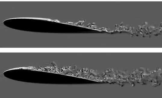
Figure 1: Instantaneous spanwise vorticity contours of the flow around a NACA 0012 at Re=5×10⁵.
(top) AOA=5◦and (bottom) AOA=8◦.
Instantaneous illustrative results of the flow in the separated region for the two AOA under study are depicted in figure 1. As can be seen from the figure, at both AOA the flow separates laminarly and transition to turbulence occurs in the separated shear layer. However, as the AOA increases, the laminar separation point moves toward the leading-edge of the airfoil increasing the height of the separated bubble, while at the same time, the turbulent separated region moves forward from the trailing edge. A detailed analysis of the mechanism of separation and the dynamics of the LSB will be presented in the final version of the manuscript.
Acknowledgements
This work has been by financially supported by the Ministerio de Educación y Ciencia, Secretaría de Estado de Universidades e Investigación, Spain (ref. ENE2010-1780) and by the Collaboration Project between Universidad Politècnica de Catalunya and Termo Fluids S.L. (ref. C06650)
References
[1] B. H. Carmichel. Low Reynolds Number airfoil Survey, Volume I. Technical report, National Aeronautics and Space Administration, 1981.
[2] K. Rinoie and N. Takemura. Oscillating behaviour of laminar separation bubble formed on an aerofoil near stall. The Aeronautical Journal, 108(1081):153–163, 2004.
[3] S. Burgmann, J. Dannemann, and W. Schröder. Time-resolved and volumetric PIV measurements of a transitional separation bubble on an SD7003 airfoil. Experiments in Fluids, 44(44):609–622, 2008.
[4] L.E. Jones, R.D. Sandberg, and N.D. Sandham. Direct numerical simulations of forced and un-forced separation bubbles on an airfoil at incidence. Journal of Fluid Mechanics, 602:175–207, 2008.
[5] H. Shan, L. Jiang, and C. Liu. Direct numerical simulation of flow separation around a naca 0012 airfoil. Computers & Fluids, 34(9):1096–1114, 2005.
[6] Y. Hoarau, D. Faghani, M. Braza, R. Perrin, Anne-Archard, and Ruiz. Direct numerical simulation of the three-dimensional transition to turbulence in the incompressible flow around a wing. Flow,
Turbulence and Combustion, 71:119–132, 2003.
[7] R. W. C. P. Verstappen and A. E. P. Veldman. Symmetry-Preserving Discretization of Turbulent Flow. Journal of Computational Physics, 187:343–368, May 2003.
[8] C. M. Rhie and W. L. Chow. Numerical study of the turbulent flow past an airfoil with trailing edge separation. AIAA Journal, 21:1525–1532, 1983.
[9] Y. Morinishi, T.S. Lund, O.V. Vasilyev, and P. Moin. Fully conservative higher order finite differ-ence schemes for incompressible flow. Journal of Computational Physics, 143(1):90–124, 1998.
[10] F.N. Felten and T.S. Lund. Kinetic energy conservation issues associated with the collocated mesh scheme for incompressible flow. Journal of Computational Physics, 215(2):465–484, 2006.
[11] P. J. Davis. Circulant Matrices. Wiley-Interscience, New York, 1979.
[12] R. M. Gray. Toeplitz and circulant matrices: A review. Foundations and Trends in Communications
and Information Theory, 2:155–239, 2006.
[13] P.N. Swarztrauber. The Methods of Cyclic Reduction, Fourier Analysis and the FACR Algorithm for the Discrete Solution of Poisson’s Equation on a Rectangle. SIAM Review, 19:490–501, 1977.
[14] M. Soria, C.D. Pérez-Segarra, and A. Oliva. A direct parallel algorithm for the efficient solu-tion of the pressure-correcsolu-tion equasolu-tion of incompressible flow problems using loosely coupled computers. Numerical Heat Transfer, Part B, 41(2):117–138, 2002.