IJEDR1902107 International Journal of Engineering Development and Research (www.ijedr.org) 569
Experimental investigation of the CFRP Anchorage
System used for CFRP Sheet In Strengthening of
R.C rectangular columns under axial static loading
1Ramadan Mohmed Aly Awad, 2Abd El-Rahman Megahid Ahmed, 3Omar Ahmed Farghal 1Consulting Eng, 2Prof. of Structural Engineering, 3Prof. of concrete Structures
Civil Eng. Dep, Faculaty of engineering, Assiut University
_____________________________________________________________________________________________________ Abstract - This paper investigates the suitability and effectiveness of the CFRP anchorage system in increasing the bond between the CFRP sheet strengthening the deferral of the reinforced concrete column rectangular cross-sections of specimens to decrease the effect of aspect ratio effect. The CFRP anchorage can transfer the stresses from the corner of the mid-face and based on the embedment depth it reaches it can transfer them in the confined area of the section .For this purpose, a detailed experimental program was conducted, which is presented here briefly. Anchoring systems are discussed herein tree gropes (E,F and G) with 15 rectangular columns cross-sections. The results of the experimental observations are discussed in the form of the stress-strain curve, ultimate bearing capacity, ductility, strain ductility , toughness , strain energy absorption capacity and failure modes. The test result, in general indicates that the use of CFRP anchor provides an enhancement in the overall ultimate bearing capacity of strengthening specimen. Three groups include 15 R.c concrete columns with composite jackets have been tested under axial compression .Test Results showed a significant increase in strength , ductility and toughness of column cross-sections due to CFRP anchorage system and confinement by CFRP .It was found that also CFRP anchorage and confinement increase the RC column compressive strength , strain in the lateral direction , and axial strain. CFRP jackets and anchorage prevent premature failure of concrete cover and buckling outwards of steel bars, leading to a ductile failure significantly improved performance of CFRP confinement concrete column rectangular cross-sections.
Keywords - CFRP Anchorage System, Confinement, FRP jackets, Ductility, Toughness.
_____________________________________________________________________________________________________ 1.INTRODUCTION
Considering the importance of columns in their structural function and the high rate of occurrence of rectangular columns in most of the buildings, a lot of study and research in improving the strength enhancement in rectangular columns has been going on for the last two decades. Several approaches have been taken, which were focused mainly on the column shape modification. The corner effect was avoided either by rounding them in the desired corner radius, in order to provide a larger area where the corner stresses can be distributed, or by modifying the column shape from rectangular to circular or elliptical by adding extra material, as an expansive cement grout in Pantelides and Yan study. Yet, these methods are not completely efficient due to structural condition and cost restrictions. Currently the most used methods of strengthening columns is are rounding the corners with radii varying from 20mm to 30mm, and installing FRP sheets with a dry or wet procedure. In order to reach a considerable increase in strength either large corner radii (~30mm) or high confinement ratio (layer thickness up to 1.5mm) were used.
Investigation of the above mentioned parameters was done on small scale specimens by Rochette Labosiere (Rochette, et al., 2000) producing an increase in strength up to 60%, but with the usage of 0.9-1.5mm thick CFRP layers, and 25-38mm rounded corners. Harris and Carey (Harris, 2003) used GFRP layers for confinement, and with the specimen, providing the least confinement (thickness 0.9mm) they got an increase of only 18%. Rousakis (Rousakis, et al.,2007) as well with the least confined specimen with CFRP layer of 0.18mm thickness, and corner radius of 30mm obtained an increase in strength of only 16%. Al-Salloum (Al-Salloum, 2007) used thick CFRP 1.2mm and obtained increase percentages varying from 43%-131% for corner radii of 5mm-50mm, respectively. Wang and Wu (Wang, et al., 2008) tested 150mmx150mmx300mm specimens and for no or 15mm corner radius, with only one layer of CFRP they achieved an increase in strength of about 3%, whereas when the confinement increased to two layers (0.34mm thick) the increase in strength reached the value of 30%.
Considering the CFRP capacity, more research should be done by effectively using the confinement provided to the columns. This paper aims to present the possible improvement of axial strength of columns by providing an anchorage configuration to overcome the existing limitation in increasing the axial capacity, ductility and toughness CFRP Anchors are employed to distribute the corner stress concentration of rectangular columns into the faces.
Depending on the radius at the corners of the cross section, the effectiveness of FRP jackets reduces significantly as the aspect ratio of the cross section approaches, values of 2–3 .
IJEDR1902107 International Journal of Engineering Development and Research (www.ijedr.org) 570 In this paper the authors investigate CFRP anchorage for CFRP confinement of rectangular RC columns in a systematic way. The study examines a number of parameters not addressed before: the effectiveness of anchorages .The role of different cross section aspect ratios (1.5,2and 3), the number of layers (0,1and 2) and the type of wrapping (to zero wrapping, full wrapping and partial wrapping). These parameters are combined in an analytical model, which was found in reasonably good agreement with the test results. CFRP jackets all groups specimens with one type of anchorage (depth =100mm, width =100mm, length =100mm, diameter of hole =14omm) ,All Groups studies the performance, effectiveness of CFRP anchorage on enhancement the externally bonded CFRP of R.C rectangular cross-section columns and the effect of aspect ratio.
The main purpose of this study is to predict an analytical model for this system of the CFRP anchorage to the enhancement of the externally bonded CFRP of R.C rectangular cross-section columns. Strengthening rectangular reinforced concrete columns by a combination of CFRP jackets and CFRP anchors or using CFRP anchors only.
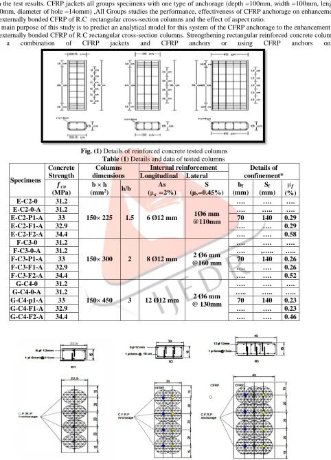
Fig. (1) Details of reinforced concrete tested columns Table (1) Details and data of tested columns
Specimens
Concrete Strength
Columns dimensions
Internal reinforcement Details of confinement* Longitudinal Lateral
𝒇𝒄𝒖
(MPa)
b × h
(mm2) h/b
As (µ𝒔 =2%)
S (µv=0.45%)
bf (mm)
Sf (mm)
µ𝒇
(%) E-C2-0 31.2
150× 225 1.5 6 Ø12 mm 1Ø6 mm @110mm
…. …. ….
E-C2-0-A 31.2 …. ….. ….
E-C2-P1-A 33 70 140 0.29
E-C2-F1-A 32.9 …. …. 0.29
E-C2-F2-A 34.4 …. …. 0.58
F-C3-0 31.2
150× 300 2 8 Ø12 mm 2 Ø6 mm @160 mm
…. …. ….
F-C3-0-A 31.2 …. ,….. …..
F-C3-P1-A 33 70 140 0.26
F-C3-F1-A 32.9 …. …. 0.26
F-C3-F2-A 34.4 …. …. 0.52
G-C4-0 31.2
150× 450 3 12 Ø12 mm 2 Ø6 mm @ 130mm
…. …. ….
G-C4-0-A 31.2 ….. ….. …..
G-C4-p1-A 33 70 140 0.23
G-C4-F1-A 32.9 …. …. 0.23
G-C4-F2-A 34.4 …. …. 0.46
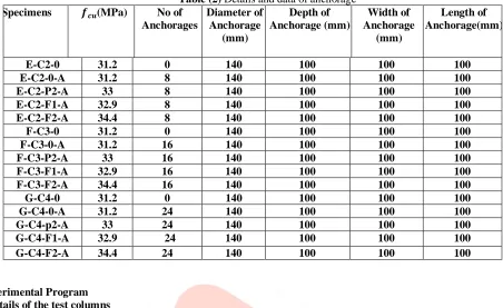
IJEDR1902107 International Journal of Engineering Development and Research (www.ijedr.org) 571 Table (2) Details and data of anchorage
Specimens 𝒇𝒄𝒖(MPa) No of
Anchorages
Diameter of Anchorage
(mm)
Depth of Anchorage (mm)
Width of Anchorage
(mm)
Length of Anchorage(mm)
E-C2-0 31.2 0 140 100 100 100
E-C2-0-A 31.2 8 140 100 100 100
E-C2-P2-A 33 8 140 100 100 100
E-C2-F1-A 32.9 8 140 100 100 100
E-C2-F2-A 34.4 8 140 100 100 100
F-C3-0 31.2 0 140 100 100 100
F-C3-0-A 31.2 16 140 100 100 100
F-C3-P2-A 33 16 140 100 100 100
F-C3-F1-A 32.9 16 140 100 100 100
F-C3-F2-A 34.4 16 140 100 100 100
G-C4-0 31.2 0 140 100 100 100
G-C4-0-A 31.2 24 140 100 100 100
G-C4-p2-A 33 24 140 100 100 100
G-C4-F1-A 32.9 24 140 100 100 100
G-C4-F2-A 34.4 24 140 100 100 100
2.Experimental Program 2.1 Details of the test columns
The smallest dimension b of all column specimens is 150 mm. All columns are short columns with constant slenderness ratio (H/b=6), where H (=900mm) is the height of the column was kept constant for all column specimens. Also, the Percentage of internal longitudinal steel µs (= 2%) and the Percentage internal lateral reinforcement µv (= 0.45%) for all specimens columns
was kept constant. The average compressive strength of standard cube and cylinder after 28 days for all tested columns were listed in Table (1). To prevent stress concentration around the corners of the specimens, the corners were rounded with the radius of 40mm.
2.2 Material properties and concrete mix proportion
Ordinary Portland cement was used throughout the program for making concrete, the water-cement ratio was 0.52 to have a slump of 80±10 mm. The fine aggregate was used natural siliceous sand with a fineness modulus of 2.60, specific gravity of 2.50 and unit weight of 15 KN/m3. The coarse aggregate was crushed gravel of 20 mm maximum nominal size, specific
gravity of 2.65 and unit weight of 15KN/m3. Drinking water was used for mixing concrete. The columns were reinforced with
high tensile steel deformed bars of grade (400/600) and diameter 12 mm used to be as longitudinal steel, while mild steel plain bars of grade (240/350) and diameter 6 mm was used as internal lateral stirrups in different columns.
The external reinforcement was a CFRP sheet (SikaWrap-230C Sika (2006)) of 0.131mm equivalent dry fiber thickness 𝑡𝑓and
the anchorage details and system according to the table (2) and Fig(2). Axial compressive loads were applied to the column specimens by using a universal testing machine of 5000 KN capacity was used in testing the columns. The LVDT data were used to calculate the mean axial shortening over the height column. Also, two vertical electrical strain gages and four transverse electrical strain gages were placed on the surface of concrete at mid-height of the specimens in case of control columns to measure the vertical and transverse strains induced in the concrete. In order to measure the transverse strain (hoop strain) on the CFRP jacket during loading, four electrical strains were placed on bond fibers in the hoop direction, at mid-height of the strengthened specimens. All instrumental equipment was connected to a data-logger system (TDS-150) which connected with computer to record the values of strains, load cell readings, and LVDT deformations during the testing at every one second.
3.Experimental Results and Discussion 3.1Failure modes
The most typical failure mechanism of the confinement without anchorage for full FRP-confined column specimens were ruptured tensile failure of CFRP in the hoop direction at or near the corner and located at mid-height of the column anchorage specimens as shown in Fig. (3). Failure of the confined specimens and anchorages occurred with cracks and warning.
At a stress level, the partially wrapped column specimens (AP-1 and AP-2) showed small cracks on the concrete surface that are equal to the unconfined and anchorage concrete strength, as shown in Fig.(3). The concrete between the CFRP strips (free spacing), started crushing while the concrete core was still confined by the CFRP strips and anchorage; this gives some warning before failure. The free spacing spilled off when the stress reached a certain high level, while the concrete under the CFRP strips , anchorage and the core were still confined, then failed without explosively by CFRP rupture the mid- height, as shown in Fig. (3).
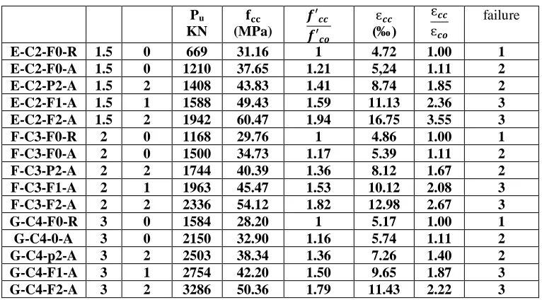
Table (3) Experimental results of testes columns
IJEDR1902107 International Journal of Engineering Development and Research (www.ijedr.org) 572 Pu
KN
𝐟𝐜𝐜
(MPa)
𝒇′𝒄𝒄
𝒇′𝒄𝒐
ԑ𝒄𝒄
(‰)
ԑ𝒄𝒄
ԑ𝒄𝒐
failure
E-C2-F0-R 1.5 0 669 31.16 1 4.72 1.00 1
E-C2-F0-A 1.5 0 1210 37.65 1.21 5,24 1.11 2 E-C2-P2-A 1.5 2 1408 43.83 1.41 8.74 1.85 2 E-C2-F1-A 1.5 1 1588 49.43 1.59 11.13 2.36 3 E-C2-F2-A 1.5 2 1942 60.47 1.94 16.75 3.55 3
F-C3-F0-R 2 0 1168 29.76 1 4.86 1.00 1
F-C3-F0-A 2 0 1500 34.73 1.17 5.39 1.11 2
F-C3-P2-A 2 2 1744 40.39 1.36 8.12 1.67 2
F-C3-F1-A 2 1 1963 45.47 1.53 10.12 2.08 3
F-C3-F2-A 2 2 2336 54.12 1.82 12.98 2.67 3
G-C4-F0-R 3 0 1584 28.20 1 5.17 1.00 1
G-C4-0-A 3 0 2150 32.90 1.16 5.74 1.11 2
G-C4-p2-A 3 2 2503 38.34 1.36 7.26 1.40 2
G-C4-F1-A 3 1 2754 42.20 1.50 9.65 1.87 3
G-C4-F2-A 3 2 3286 50.36 1.79 11.43 2.22 3
*Mode of failure
1-Concrete crushing without Longitudinal cracks .
2-Spalling of concrete cover and buckling of the main longitudinal reinforcement with pullout of anchorage. 3-FRP rupture after concrete crushing and rupture of the splayed FRP anchor fibers
h 3 2
2
1 3 3
Fig (3) Failure modes of testing columns 3.2Effect of aspect ratio on strength
The values of the axial strength ratio for one layer and two layers CFRP-confined rectangular columns (h/b=1.5) are 1.59 and 1.94 respectively, whereas those for the rectangular column specimens with the higher aspect ratio of 3 (h/b=3) are smaller 1.5 and 1.79 respectively. That means the improvement of gaining strength decreased as the aspect ratio increased.
Fig (4) Gain strength versus aspect ratio There is an insignificant gained strength for columns with an aspect ratio of 3 (h/b=3) for one and two layers.
The variation of gaining strength versus cross sectional aspect ratios (h/b) of columns confined with zero, one, and two layers of CFRP sheets was plotted As shown in Fig (4). For fully confined, the highest value of axial compressive strength ratio (𝒇′𝐜𝐜/𝒇𝒇′𝐜𝐨).
1 1.5 2
1.5 2 2.5 3 3.5
f
cc/
f
co
Aspect Ratio b/h
F-2 with anchorage
IJEDR1902107 International Journal of Engineering Development and Research (www.ijedr.org) 573 Column (G-C4-F-2) ( 𝒇′𝐜𝐜/𝒇′𝐜𝐨). = 1.79) while low values were found in rectangular columns h/b=3 (G-C4-F-1)
) ( 𝒇′𝐜𝐜/𝒇′𝐜𝐨). =1.4). The strengthening ratios of confined columns are proportional to the thickness of FRP layer and inversely proportional with a cross sectional aspect ratio. FRP-confined columns with higher aspect ratios (h/b >1.5).
For partially CFRP confined columns, the strength ratio increased as aspect ratio was 41%, 36and 36% when aspect ratio was 1.5, 2 and 3 respectively. In all cases of confinement the fully confined columns showed a higher gained strength and the load carrying capacity in comparison with the corresponding Partially confined columns with a same CFRP confinement ratio (µf). For same CFRP confinement ratio (µf), the improvements in gaining strength, four fully confined columns were
159%,153% and150%, and lower improvements for partially confined 2 layers 141%, 136 and 136% when aspect ratios were 1.5, 2 and 3 respectively,. Therefore, partially confined system not recommended applying for rectangular section columns, particularly, that which has an aspect ratio (h/b ≥ 1.5).
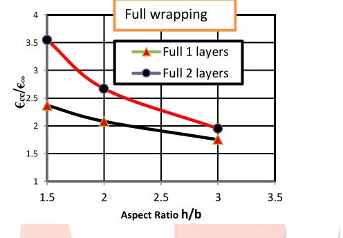
3.3Effect of aspect ratio on axial strain
The confinement effect of FRP enhancing in concrete strain capacity more than increases concrete axial compressive strength. For rectangular columns, the FRP confinement effectiveness is more significant in terms of enhancement of concrete axial strain rather than increment in axial strength. The strain improvement of confined concrete for square columns showed better enhancement more than rectangular columns. Moreover, the enhancement in confined axial strain decrease by increasing the cross sectional aspect ratio of rectangular columns.
Fig (5) Gain compressive strain versus aspect ratio CFRP sheets, were equal to 3.55, 2.67 and 1.85 respectively. This proves that the FRP confinement enhances the deformation characteristics of concrete columns as well. Moreover, it is clear from Fig. (5), that the axial strain efficiency factor decreased with increasing aspect ratios due to less confinement effect. The axial strain efficiency factor increased with increasing the thickness of CFRP from one layer to two layers. The axial strain efficiency factor increased about 2.37 times for rectangular sections with aspect ratio ( h/b ≤ 1.5) and about 1.85 times for a rectangular section with aspect ratio (h/b >1.5).
For partially confined system, the load carrying capacity decreased as aspect ratio increased: the improvement in the axial strain was 85%, 67and 40% when aspect ratio was 1.5, 2 and 3 Partially confined system showed a noticeable enhancement in concrete strain capacity for rectangular section columns, particularly, those of lower aspect ratio (h/b ≤ 1.5). In addition to being more ductile than unconfined columns, the failure behavior of the partially confined samples showed an alert and warning before the failure in comparison to the fully confined system, which fails suddenly without warning.
3.4Effect of aspect on ductility
Columns particularly, those of lower aspect ratio (h/b ≤ 1.5). In addition to being more ductile than the unconfined columns failure behavior of the partially confined samples showed an alert and warning before the failure in comparison to the fully confined and anchorage system.
Ductility of a member is defined as its ability to sustain inelastic deformations prior to collapse, without substantial loss of strength. A ductile system displays sufficient warning before catastrophic failure. Ductility is generally measured by the ratio of the (ultimate deformation—deflection, curvature, or rotation—to that at the first yielding of steel reinforcement).
Ductility index follows the conventional definition of ductility, as 𝜇𝐷= ∆𝑢⁄∆𝑦, where ∆𝑢and ∆𝑦= ultimate and yield
deflections, respectively.
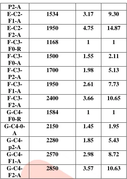
From table (4) and fig (6) test results described that CFRP-confinement and anchorage can significantly enhance the ductility index of the specimens.
Specime ns
𝐔𝐥𝐭𝐦𝐚𝐭𝐞
𝑳𝒐𝒂𝒅𝒔(𝐊𝐍) Ductility Index
Toughn ess Index
E-C2-F0-R
669 1 1
E-C2-F0-A
1210 1.62 2.71
E-C2- 1280 2.15 6.14
1 1.5 2 2.5 3 3.5 4
1.5 2 2.5 3 3.5
€
cc
/
€
co
Aspect Ratio h/b
IJEDR1902107 International Journal of Engineering Development and Research (www.ijedr.org) 574 P2-A
E-C2-F1-A
1534 3.17 9.30
E-C2-F2-A
1950 4.75 14.87
F-C3-F0-R
1168 1 1
F-C3-F0-A
1500 1.55 2.11
F-C3-P2-A
1700 1.98 5.13
F-C3-F1-A
1950 2.61 7.73
F-C3-F2-A
2400 3.66 10.65
G-C4-F0-R
1584 1 1
G-C4-0-A
2150 1.45 1.95
G-C4-p2-A
2280 1.85 5.43
G-C4-F1-A
2570 2.98 8.72
G-C4-F2-A
2850 3.57 10.63
Table (4) Experimental test results of the specimens indicted the Ductility Index and Toughness index average ratio of the ultimate deflection at rupture, over the axial strain corresponding to yield deflections.
Where the average ratio of the FRP ultimate axial strains at rupture, over the axial strain corresponding to yield strain. (𝜺′𝐜𝒄/𝜺′𝐜𝐲) for E-C2 (rectangular with aspect ratio 1.5 ) increases by 1.15- 2.17 and 3.75 % for C2-P-2 ply, C2-F-1 ply and 2 plies of CFRP jacket and anchorage respectively. Where the average ratio of the ultimate axial strain at rupture, over The axial strains corresponding to yield strain. (𝜺′𝐜𝒄/𝜺′𝐜𝐨) for series 2 (rectangular with aspect ratio 2 ) increases by increases by 98 -1.61 and 2.66 % for C3-P-2 ply, C3-F-1 ply and 2 plies of CFRP jacket and anchorage respectively.
Where the average ratio of the ultimate axial strains at rupture, over the axial strain corresponding to yield strain. (𝜺′𝐜𝒄/𝜺′𝐜𝐨) for C 4 (rectangular with aspect ratio 3 ) increases by 85-1.98 and 2.58 % for C4-P-2 ply, C4-F-1 ply and 2 plies of CFRP jacket and anchorage respectively.
From the above analysis, it is obvious that increase the number of CFRP lyres and an anchorages give increase of the ductility index also decrease the aspect ratio lead to enhance and increase of the ductility index. High ductility Prevented the abrupt failure of the damaged columns, thereby showing an improvement in ultimate displacement. Both these factors summed up to provide a better ductile response for the rehabilitated.Specimens compared to that of the control specimen Increase the ductility index improved and enhanced the bearing capacity of the columns agents the seismic load.
3.5Effect of aspect ratio on toughness
Toughness has been suggested as a measure of deformability of such members, since it generally
Table (4) Experimental test results of the specimens indicates the ability to resist crack growth (or fast fracture).
Toughness i s calculated by integrating the area under the load deflection curve, large deformation do not necessarily warrant a ductile failure, because they may be due to low stiffness. Linear-elastic response of FRP reinforcement often stores large amounts of elastic energy in the structure, release of which may prove devastating.Toughness is a measure of the energy absorbing capacity of the composite. Increased toughness means – improved performance in fatigue, impact and impulse loading and it also provides ductility, i.e. the ability to undergo larger shortenings before failure, it is often measured using a toughness index.
IJEDR1902107 International Journal of Engineering Development and Research (www.ijedr.org) 575 Where the average ratio of the ultimate axial strains at rupture, over the axial strain corresponding to yield strain. (𝜺′𝐜𝒄/𝜺′𝐜𝐨) for C 4 (rectangular with aspect ratio 3 ) increases by4.13 -6.72 and 9.66 % for C4-P-2 ply, C4-F-1 ply and 2 plies of CFRP jacket and anchorage respectively.
From table (4) and fig (7)Test results indicate that CFRP-confinement and anchorage can significantly enhance the toughness index of the specimens.
Fig (6)Ductility index versus aspect ratio Fig (7) Toughness index versus aspect ratio 4.ANALYTICAL MODELS
4.1Analytical Modeling for FRP-Confined and anchorage Rectangular Columns.
Columns without anchors or with light anchors which fail prematurely, the effectively confined area Ae is defined by the parabolas in Fig. 8 a. In the presence of heavy anchors, which remain intact at jacket failure, the effectively confined area is modified as shown in Fig. 8 b. To account for the use of anchors at vertical spacing equal to 𝑆𝑎, each of the points where two
parabolas meet at anchor locations (A in Fig. 8 b) should be displaced towards the interior of the cross section. This displacement is maximized at cross sections where confinement is minimized, that is at mid-height between anchor locations. Hence, assuming that all points A are displaced along a (vertical) parabola, as it is typically assumed in the case of steel stirrups, the maximum displacement of points A equals sa/4 and the effectively confined area becomes as shown in Fig. 8 –c sections, Ae&bh - Aun, where An area of unconfined concrete, calculated as follows
Fig(8):- Effectively confined cross section areas: a cross section in columns without anchors or with light anchors, which failed prematurely, by columns with heavy anchors, cross section at the location of anchors, and c columns with heavy anchors, cross section at mid-height between anchors , Triantafillou et al [10]. From Fig (8) area and te effect of the CFRP anchorage on the mechanism of the confinement of the rectangular cross-section R.C columns ,Triantafillou et al [10].
𝐴𝑢𝑛= 2(𝑛 + 1)23(ℎ−2𝑅)
2
(𝑛+1)244
1 2
(ℎ−2𝑅)𝑠𝑎
(𝑛+1)4 + 2(𝑛 − 1)
(ℎ−2𝑅)𝑠𝑎
(𝑛+1)4 + 2 2 3
(𝑏−2𝑅)2
4 (1)
Finally, the confinement effectiveness factor is given as:
𝐾𝑎≈𝐴𝑏ℎ𝑒≈𝑏ℎ−𝐴𝑏ℎ𝑢𝑛 (2)
𝐾𝑎=1 −(ℎ−2𝑅)(ℎ−2𝑅+1.5𝑛𝑠𝑎)+(𝑛+1)(𝑏−2𝑅)
2
3(𝑛+1) (3)
In this study to apply the analytical model n is the number of CFRP anchorage of the confined cross-section and 𝑠𝑎= 0.
(4)
• ACI 440.2R-08 (ACI, 2008)
According to ACI 440.2R-08, the nominal axial
The maximum confined concrete compressive strength 𝑓𝑐𝑐, and the maximum confinement pressure 𝑓𝑙 are calculated using
Eq. (5) and (7), respectively
𝑓𝑐𝑐, = 𝑓𝑐,+ 3.3 𝑘𝑎𝑓𝑙 (5)
The efficiency factor or shape factor (𝑘𝑎) accounts for the geometry of the section, for non-circular 𝑘𝑎 defined as:
𝑘𝑎= (𝑏ℎ) 2 𝑘𝑒 , 𝑘𝑒=𝐴𝐴𝑒 𝑐𝑐= 1−[ 𝑏
ℎ(ℎ−2𝑟𝑐)2+ℎ𝑏(𝑏−2𝑟𝑐)2 3𝐴𝑔 ]−𝜌𝑠𝑐
1−𝜌𝑠𝑐 (6)
𝐴𝑒is the area of effectively confined concrete core of the column section with rounded corner 𝑟𝑐 and (ρsc=𝐴𝐴𝑠
𝑔) is the cross-sectional area ratio of the longitudinal steel reinforcement, the net cross section area(𝐴𝑐𝑐= 𝐴𝑔− 𝐴𝑠).
𝑓𝑙=
2𝑛𝑓𝑡𝑓𝐸𝑓𝜀𝑓𝑒
𝐷 (7) 1 1.5 2 2.5 3 3.5 4 4.5 5
1.5 1.75 2 2.25 2.5 2.75 3 3.25
D uct ili ty In de x
Aspect Ratio h/b
Full Rwapping
2 layers
1 layer
1 3 5 7 9 11 13 15 17 191.5 2 2.5 3 3.5
To ugh ne ss In de x
Aspect Ratio h/b
Full wrapping
2 layers
IJEDR1902107 International Journal of Engineering Development and Research (www.ijedr.org) 576 𝜀𝑓𝑒= 𝑘𝜀𝜀𝑓𝑢𝑙𝑡 Where 𝑘𝜀= 0.55 for non-circular section. (8)
𝑓𝑐, is the unconfined cylinder compressive strength of concrete, nf is the number of FRP layers, Ef is the elastic modulus of the
FRP sheet, , tf is the thickness of FRP sheet and εfe is the effective strain of FRP wraps at failure, given as equal to 0·55 times
the ultimate tensile strain of the FRP sheets. The diameter of an equivalent circular column (D) is defined as: 𝐷 = √𝑏2+ ℎ2 (9)
• Egyptian Code Model
According to E.C, the nominal axial The maximum confined concrete compressive strength 𝑓𝑐𝑐, and the maximum confinement
pressure 𝑓𝑙 are calculated using Eq. (10) and (11), respectively
𝑓𝑐𝑐𝑢= 𝑓𝑐𝑢[2.25√1 + 9.875𝑓𝑓𝑙
𝑐𝑢− 2.5
𝑓𝑙
𝑓𝑐𝑢− 1.25] (10)
Where 𝑓𝑐𝑢 is the concrete compressive strength for standard cube.
𝑓𝑙= 𝑘𝑒 𝜇𝑓𝐸𝑓𝜀𝑓𝑒
2 (11)
𝑘𝑒 The effective confined accounts for the geometric shape of the section, for a rectangular section defined as:
𝑘𝑒=𝐴𝐴𝑒
𝑐𝑐= 1 − [
(ℎ−2𝑟𝑐)2+(𝑏−2𝑟𝑐)2
3(𝑏×ℎ)(1−μ𝑠) ] (12)
The ratio of the volume of the wrapped reinforcement cross-sectional area of the wrapping material to the volume of confined concrete core Ac per unit length for a rectangular full wrapped columns (𝜇𝑓) is calculated according to Eq. (13) .
𝜇𝑓=
2 𝑛𝑓.𝑡𝑓 (𝑏+ℎ)
𝑏ℎ (13)
𝜀𝑓𝑒is the effective strain of the wrapped FRP sheet at the failure which, should be limited as Eq. (14).
𝜀𝑓𝑒= 0.75𝜀𝑓𝑢𝑙𝑡 ≤ 0.004 (14)
The efficiency factor or shape factor (𝑘𝑒) is calculated according to the Proposed equation of each selected model (Eq. (6) &
Eq. (12) for ACI and EC code respectively). Proposed Analytical Model
𝑓𝑐𝑐,, the maximum confined concrete compressive strength is calculated using suggested Eq.(15) & Eq.(16) instead of Eq.(5)
and Eq.(10) according to ACI and EC respectively, for EC Eq.(16)
𝑓𝑐𝑐,, = 𝑓𝑐,+ 3.3𝑓𝑙∗∗ (15)
𝑓𝑐𝑐,, = 𝑓𝑐,[2.25√1 + 9.875 𝑓𝑙∗∗
𝑓𝑐, − 2.5 𝑓𝑙∗∗
𝑓𝑐, − 1.25] (16)
Where (𝑓𝑐,= 0.8𝑓𝑐𝑢 ) for cylinder strength.
𝑓𝑙∗∗ is the effective lateral confining pressure is obtained according to Eq. (17).The confining pressure depends mainly on the
shape of cross-section, the type of confinement, anchorage system and mechanical properties of FRP composites.
𝑓𝑙∗∗= 𝑘𝑒𝑘𝑝 𝑓𝑙 (17)
𝑘𝑝 is the confinement effectiveness coefficient deal with type of confinement is calculated according to Eq.(18), (19).
𝑘𝑝=
[1−2(ℎ−2𝑟𝑐)𝑠, ][1−2(𝑏−2𝑟𝑐)𝑠, ]
1−𝜇𝑠 < 1.0 For partial wrapping (18)
𝑘𝑝= 1 For full wrapping (19)
𝑓𝑙 is the effective lateral confining pressure obtained according to Eq.(7),and Eq.(11) for ACI and EC code
Analytical Verification
The selecting analytical models for rectangular reinforced concrete columns described in the previous section were assessed by comparing analytical values with corresponding experimental results. The experimental results from this study was used to evaluate the analytical models, and the average ratios between theoretical and experimental strengthens ratio.The coefficients of variation, and the Correlation factor were calculated to evaluate the performance of the analytical models.
𝑓𝑐𝑐′pr1 according to Eq.(16) based on the modified expression suggested by E.C, and Ppr2 according to ACI-8 according to
Eq. (15) were calculated and reported in Table (5) together with the corresponding obtained experimental results for the different tested columns. As shown in Tables (5), it was found a good correlation factor was obtained between the experimental results and those got from the theoretical model by (E.C), (ACI) of 7. 14% and 4.75% respectively, and excellent correlation factor of 0.92, 0.95 for (E.C), (ACI) respectively, with standard deviation of 5.5 and 3.42%.
Table (5) Analytical verification of testing according to Eq.(17) based on selected model Column Experimental
results
Predicted results
𝑓𝑐𝑐′pre (Mpa)
𝑓𝑐𝑐 𝑝𝑟𝑒′
𝑓𝑐𝑐 𝐸𝑋′
𝒇𝒄𝒄′ (Mpa) (E.C) (ACI2008) (E.C) (ACI2008)
E-C2-P2-A 43.83 31.19 30.67 0.71 0.70
E-C2-F1-A 49. 43 37.00 34.59 0.62 0.70
E-C2-F2-A 60.47 45.61 41.18 0.75 0.68
F-C3-P2-A 40.39 31.15 30.32 0.77 0.75
F-C3-F1-A 45.47 36.12 33.16 0.79 0.73
F-C3-F2-A 54.12 45.03 34.55 0.83 0.64
G-C4-p2-A 38.34 31.11 29.71 0.81 0.77
G-C4-F1-A 42.20 35.61 31.50 0.84 0.75
IJEDR1902107 International Journal of Engineering Development and Research (www.ijedr.org) 577
Average 0.77 0.72
Standard deviation %
5.50 3.42
Coefficient of variation
7.14 4.75
Correlation factor
0.92 0.95
5.Conclusions
According to the experimental tests on CFRP confined with CFRP anchorage rectangular R.C columns and the performed analytical verifications, the main conclusions are noted below:-
1-The CFRP anchorage transfer the stresses from the corner to the mid-face and based on the embedment depth it can transfer them in the confined area of all the sections .
2-The fan part of the anchorage can accumulate the stresses of the corner and transfer them to the inner confined concrete core, by proving a hoop-like confinement for that portion where the anchorage is placed.
3-CFRP jackets and combined with CFRP anchorage these lead to ductile failure instead of brittle failure and gradually warning without explosive before failure.
4-Confinement by CFRP sheets and anchorage enhances the performance of rectangular RC columns under axial compressive loads, improve the strength , ductility and toughness of RC columns regardless the cross sectional aspect ratio and system type of confinement. In addition, increasing in the thickness of CFRP, increases the gain in compressive strength and axial strain with respect to unconfined columns.
5-Strain hardening was observed, when there is a sufficient level of confinement as showed on different confined columns, but the strain was observed on the partially confined Rectangular columns with aspect ratio (h/b=3).
6-The proposed model gives reasonable predictions of the test results, with a good correlation factor of 0·95 and the lower coefficient of variation equal to 4.75%.
7-To predict the compressive strength of CFRP-confined columns confined and anchorage, the applied of Eq. (15) based on models ACI showed a better estimate, particularly, in case of E-C models for unconfined and partially confined of all tested columns. EC models based on Eq.(16), showed an acceptable estimate, particularly, in case of fully confined rectangular columns approaching to the experimental results. E.C model based on Eq.(16) for fully and partially confined of rectangular columns with (h/b>1.5), showed an acceptable estimation approaching to the experimental results.
6.References
[1] Pantelides, C., Yan, Z., “Confinement Model of Concrete with Externally Bonded FRP Jackets or Posttensioned FRP Shells”. Journal of Structural Engineering, V. 133, No.9, 2007, pp. 1288–1296
[2] Rochette, P., and Labossiere, P. "A Plasticity Approach for Concrete Columns Confined with Composite Materials." Proceedings of the Second International Conference on Advanced Composite Materials in Bridges and Structure, Canadian Society for Civil Engineering,Montreal, Canada, 359-366.
[3] Harries, K.A., and Kharel, G. (2003). "Experimental Investigation of the Behaviour of Variably Confined Concrete." Cement and Concrete Research, 33(6), 873-880.
[4] Roussakis, TC, and Karabinis, AI, 2007, Substandard reinforced concrete members subjected to compression: FRP confining effects. Materials and Structures, 41: 1595-1611.
[5] Y.A. Al-Salloum, Y.A., “Influence of Edge Sharpness on the Strength of Square Concrete Columns Confined With FRP Composite Laminates”, J. Composite Part B, vol. 38, pp. 640–650, 2007.
[6] Wang, L.M.; Wu, Y.F. Effect of corner radius on the performance of CFRP-confined square concrete columns:Test. Eng. Struct. 2008, 30, 493–505. [CrossRef] .
[7] FRP confinement of wall-like reinforced concrete columns,.T. C. Triantafillou • E. Choutopoulou • E. Fotaki •M. Skorda • M. Stathopoulou • K. Karlos .3 January 2015.
[8] ACI 440.2R-08. (2008). Guide for the esign and Construction of Externally Bonded FRP Systems for Strengthening concrete Structures, American Concrete Institute, Detroit, ichigan, USA..ST03-05, Univ. of South Carolina, Columbia, S.C. [9] SIKA (2006); Technical Report: Product Data Sheet, Edition 2006.
[10] Triantafillou TC, Choutopoulou E, Fotaki E et al. (2016). “FRP confinement of wall like reinforced concrete columns. Materials and Structures 49(1): 651–664.
[11] EC 208 (2005). Egyptian Code for Design Principals and Construction Specifications of Using FRP System for Construction, Ministry of Housing, Facilities and Constructional Development, National Center for Housing and Construction Research, Egypt (2005).