POWER FACTOR IMPROVEMENT IN ELECTRODE-LESS
FLUORESCENT LAMP USING FUZZY LOGIC CONTROLLER
1
D. Vinoth, 2P. Jothimani, *3C. Rajkumar, 4G. Naveen Kumar
1
Assistant Professor, EEE Department, Muthayammal College of Engineering, Rasipuram.
2,3,4
UG Students, EEE Department, Muthayammal College of Engineering, Rasipuram.
Article Received on 06/02/2019 Article Revised on 27/02/2019 Article Accepted on 17/03/2019
ABSTRACT
This paper deals with the power factor of Electrode- less Fluorescent
Lamp (EFLs) by using fuzzy logic controller. The output voltage of the
cuk converter contains voltage ripples and steady state error. To
overcome the voltage ripples and steady state error, the closed loop
system of Fuzzy Logic Controller (FLC) and Single Ended Primary
Inductor Converter (SEPIC) are used. By using FLC, the power factor and the efficiency are
slightly get increased when compared to Proportional Integral (PI). The SEPIC is used to
reduce the voltage ripples. PI controllers are not much efficient and require more time to
implement due to their robustness. These controllers are suitable for single input value only
not suitable for changing values. The FLC is proposed to improve the efficiency and more
number of inputs can be used. Finally, a step-by-step design methodology is proposed and
stimulated through MATLAB/SIMULINK for improving the power factor and efficiency by
reducing the voltage ripples.
KEYWORDS: SEPIC converter, Fuzzy logic controller (FLC), fuzzy rules, Power factor.
I INTRODUCTION
In this modern world, the usage of electricity is increasing and the production of electricity is
decreasing. One way to reduce the electrical energy consumption is the use of high frequency
electrode less electronic ballasts feeding discharge lamp. The ordinary fluorescent lamp
works on the principle, when the lamp is off, no current flows through the tubes .The gas
mixture is highly ionized and an arc is generated between the two terminals of the lamp
World Journal of Engineering Research and Technology
WJERT
www.wjert.org
SJIF Impact Factor: 5.218*Corresponding Author
C. Rajkumar
UG Students, EEE
Normally we are using Fluorescent Lamp (FL‟s) which is having less life time, low
efficiency and more switching losses when compared to Electrode less Fluorescent Lamp (EFL‟s). The absence of electrodes is the main advantage of EFL‟s that makes possible a
higher lifetime. In EFL‟s, to improve the power factor and efficiency here we are using
Fuzzy Logic Controller (FLC) instead of PI controller which reduces the complex circuit.
Generally the electrode less fluorescent lamp works in which the power required to generate
light is transferred from outside the lamp envelope to the gas inside via an electric or
magnetic field, in contrast with a typical gas discharge lamp that uses internal electrodes
connected to the power supply by conductors that pass through the lamp envelop. There are
three advantages to elimination of the internal electrodes, extended lamp life, because the
internal electrodes are usually the limiting factor in lamp. The ability to use light-generating
substances of higher efficiency that would react with internal metal electrodes in normal
lamps. Improved collection efficiency because the source can be made very small without
shortening life, a problem in internal electrode lamps.
II Sepic Description
Single-ended primary-inductor converter (SEPIC) is a type of DC-DC converter allowing
the electrical potential (voltage) at its output to be greater than, less than, or equal to that at
its input; the output of the SEPIC is controlled by the duty cycle. It has advantages of having
non-inverted output (ie) the output has the same voltage polarity as the input by using a
series capacitor to couple energy from the input to the output. It has a capable of true
shutdown: when the switch is turned off, its output drops to 0 V, following a fairly hefty
transient dump of charge.
All dc-dc converters operate by rapidly turning on and off a MOSFET, generally with a high
frequency pulse. What the converter does as a result of this is what makes the SEPIC
converter superior. For the SEPIC, when the pulse is high/the MOSFET is on, inductor 1 is
charged by the input voltage and inductor 2 is charged by capacitor 1 is shown in the mode 1
operation of figure.1. The diode is off and the output is maintained by capacitor 2. When the
pulse is low/the MOSFET is off, the inductors output through the diode to the load and the
capacitors are charged is done by mode 2 operation is shown in the figure.2. The greater the
percentage of time (duty cycle) the pulse is low, the greater the output will be. This is
because the longer the inductors charge, the greater their voltage will be. However, if the
Mode 1 Operation of Sepic
Figure 1: Mode 1 operation circuit of SEPIC.
Mode 2 Operation of Sepic
Figure 2: Mode 2 operation circuit of SEPIC.
III Block Diagram of Proposed System
The figure.3 shows the block diagram of the proposed method of ELF‟s & it consists of a
bridge rectifier and it converts the ac source into dc source. Here the converter circuit, used
is Single Ended Primary Inductance Converter (SEPIC) in this type of converter output
voltage to be greater than or less than or equal to that at its input the output of the SEPIC is
controlled by the duty cycle. In the SEPIC the output voltage will have the same polarity
when compared to input. The supply voltage and current are get measured and it is given to
the Fuzzy Logic Controller (FLC).
The FLC system analyzes analog input values in terms of logical variables that take on
continuous values between 0 and 1, in contrast to classical or digital logic, which operates on
discrete values of either 1 or 0 (true or false). The output of the FLC is given to the pulse
width modulation to make the power electronic switches to turn on and turn off according to
the duty cycle. If the duty cycle is >50%, then the converter will act as the buck converter
and if the duty cycle is <50%, then the converter will act as the boost converter. Then the
output of the converter is given to the inverter circuit which converts the DC supply to AC
supply. Then the output of the inverter circuit is given to load which is the electrode less
fluorescent lamp.
AC Source Voltage
It is the first stage of this paper. So it is give the AC supply to rectifier circuit.
Rectifier
It is the second stage of this paper. The rectifier circuit converts the AC source voltage into
DC voltage. So it is give the DC supply to DC-DC converter circuit.
DC-DC Converter
A boost converter (step-up converter) is a DC-to-DC power converter with an output voltage
greater than its input voltage. The dc output voltage is obtained by using a full bridge
rectifier. The capacitor filter is used to reduce the output voltage ripples.
Voltage and Current Measurement Unit
The voltage and current measurement units are placed before the converter. These units are
used to measure the actual voltage and current from the source and fed the measurements to
the fuzzy logic controller. These measurements are converted into single input using a
multiplexer.
Pulse Width Modulation (PWM)
Pulse Width Modulated (PWM) converters have been widely used in industry. The PWM
technique is praised for its high power capability and ease of control. Higher power density,
faster transient response and smaller physical size of PWM converters can be achieved by
increasing the switching frequency. However, as the switching frequency increases so do the
switching losses and electromagnetic interference (EMI) noises. Switching losses and EMI
Fuzzy Logic Controller (FLC)
The fuzzy logic controller used in this paper is to reduce the voltage ripples and to improve
the efficiency of the converter. There are set of 49 rules are formed using the membership
functions. The controller uses mamdani method which is suitable for variable values. The
membership functions are formed by using triangular membership functions.
In the fuzzy logic controller algorithm, there consists of set rules that are to be followed,
The fuzzifier has the effect of transforming crisp measured data (e.g. speed is 10 mph) into
suitable linguistic values (i.e. fuzzy sets, for example, speed is too slow). The fuzzy rule base
stores the empirical knowledge of the operation of the process of the domain experts. The
interface engine is the kernel of a FLC, and it has the capability of simulating human
decision making by performing approximate reasoning to achieve a desired control strategy.
The defuzzifier is utilized to yield a non fuzzy decision or control action from an inferred
fuzzy control action by the inference engine. If the output from the defuzzifier is not a
control action for a plant, then the system is fuzzy logic decision system.
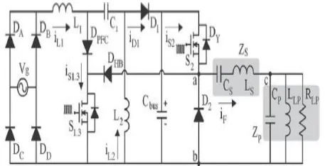
IV Circuit Diagram And Description
The figure.4 shows the basic circuit diagram of the entire model of dc motor drive with
SEPIC converter. The circuit diagram is consists of a ac-dc converter and it converts the ac
source in to fixed dc source. In this converter consists of four diodes are connected like
bridge (i.e.) two in series and the two series of parallel which gives full wave rectification and
the filter capacitor is used to remove the ripples from the output voltage. After this it will be
input of the SEPIC converter which converts the fixed dc source in to variable dc source
required for the dc motor drive speed control. Like buck-boost converter, SEPIC converter is
also delivers an inverted output but the only difference it has an additional inductor and
capacitor. Note that virtually all of the output current must pass through C1, and as ripple
current. So C1 is usually a large electrolytic with a high ripple current rating and low ESR
Figure 4: Circuit diagram of proposed method of EFL‟s.
The circuit diagram is consists of a AC-DC converter and it converts the ac source in to fixed
dc source. In this converter consists of four diodes are connected like bridge (i.e.) two in
series and the two series of parallel which gives full wave rectification and the filter capacitor
is used to remove the ripples from the output voltage. After this it will be input of the SEPIC
converter which converts the fixed dc source in to variable dc source is given to the inverter
circuit. Like buck-boost converter, SEPIC converter is also delivers an inverted output but
the only difference it has an additional inductor and capacitor. Note that virtually all of the
output current must pass through C1, and as ripple current. So C1 is usually a large
electrolytic with a high ripple current rating and low ESR (equivalent series resistance) to
minimize the losses. The input voltage and current are get measured and is given as the input
to the fuzzy logic controller (FLC) and the generated output is given to the pulse width
modulation. The pulse width modulation generates the required frequency and is given to the
converter and the inverter circuit. The PWM signal decides which switch is to be turned on
and turned off. The output of the converter circuit is given to inverter circuit which converts
the DC signal to AC signal and the AC signal is given to the load. Here the load is electrode
less fluorescent lamp by dimmable electronic ballast.
V Simulation Results of Proposed Method
Simulation results of power factor improvement in electrode-less fluorescent lamp using
fuzzy logic controller is obtained using MATLAB/SIMULINK. MATLAB is a high-
performance language for technical computing. It integrates computation, visualization, and
programming in an easy-to- use environment where problems and solutions are expressed in
familiar mathematical notation. In the proposed method simulation diagram the input
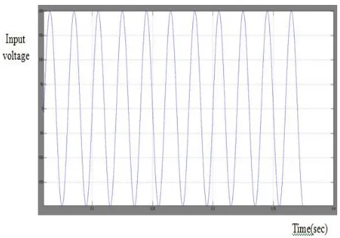
Figure 5: Waveform of input voltage.
Figure.5 shows the input voltage and input current given to the simulation circuit. Here the
input voltage 220v is given to the simulation diagram of the proposed system.220v supply
voltage is given to the uncontrolled diode bridge rectifier. The measured values of current
and voltage are given to the FLC circuit. The output waveform of power factor correction
shown in the figure.8.
Figure 6: Waveform of converter output voltage.
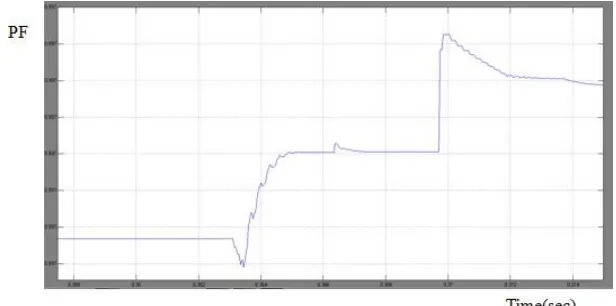
Figure 8: Waveform of power factor using Fuzzy Logic Controller.
VI CONCLUSION
Here the real power and reactive power is calculated by using of fuzzy logic controller and PI
controller is calculated. while using PI controller the PF is 0.97 & while using fuzzy logic
controller the PF is get increased to 0.99 for designing the closed loop system for electrode
less fluorescent lamp by dimmable electronic ballast. The SEPIC reduces the number of
power switching devices connected with inverter circuit and it boost up the input voltage.
The SEPIC is designed to eliminate the use of EMI filter and voltage ripples are reduced. By
using FLC, the system becomes closed loop. Instead of using the PI controller, FLC is used
so that power factor and efficiency is increased. The output voltage is stepped up to 450V,
when the input voltage is 220V. The power factor is about 0.9 and the efficiency is about
90% to 95%. Thus, the performance of FLC and SEPIC is superior when compared to PI
controller and cuk converter.
V REFERENCES
1. Avestruz, J. J. Cooley, D. Vickery, J. Paris, and S. B. Leeb, “Dimmable solid state ballast with integral capacitive occupancy sensor,” IEEE Trans. Ind. Electron., 2012; 59(4).
2. F. E. Bisogno, A. R. Seidel, R. Holsbach, and R. N. Do Prado, “Resonant filter applications in electronic ballast,” in Conf. Rec. 37th IEEE IAS Annu. Meeting, 2002; 1:
348–354.
3. C.Nagarajan and M.Madheswaran, „Experimental verification and stability state space
analysis of CLL-T Series Parallel Resonant Converter with fuzzy controller‟ - Journal of
4. R.Raja and C.Nagarajan, “Performance Analysis of LCL-T Filter Based 2 Stage Single
Phase Gird Connected Module with ANN Controller using PV Panel," Current Signal
Transduction Therapy, 2018; 13(2): 159-167.
5. C.Nagarajan and M.Madheswaran, “Performance Analysis of LCL-T Resonant Converter with Fuzzy/PID Using State Space Analysis” Springer, Electrical Engineering, 2011;
93(3): 167-178.
6. E.Geetha, C. Nagarajan, “Stochastic Rule Control Algorithm Based Enlistment of
Induction Motor Parameters Monitoring in IoT Applications," Wireless Personal
Communications, 2018; 102(4): 3629–3645.
7. M.Madheswaran, C.Nagarajan, “DSP Based Fuzzy Controller for Series Parallel
Resonant converter”, Frontiers of Electrical and Electronic Engineering, 2012; 7(4):
438-446.
8. C.Nagarajan, “Single-Stage High-Frequency Resonantac/AC Converter Using Fuzzy Logic and Artificial Neural networks‟, Conference on Emerging Devices and Smart
Systems (ICEDSS), 2nd and 3rd March, organized by mahendra Engineering College,
Mallasamudram, 2018; 30-37.
9. E Geetha, C Nagarajan, “Induction Motor Fault Detection and Classification Using Current Signature Analysis Technique”, Conference on Emerging Devices and Smart
Systems (ICEDSS), 2nd and 3rd March, organized by mahendra Engineering College,
Mallasamudram, 2018; 48-52.
10.GS SatheeshKumar, C Nagarajan, ST Selvi, “A Virtual Impedance Based Analysis of
Dynamic Stability in a Micro-Grid System”, Conference on Emerging Devices and Smart
Systems (ICEDSS), 2nd and 3rd March, organized by mahendra Engineering College,
Mallasamudram, 2018; 38-41.
11.CS Lakshmi, C Nagarajan, “Neural Controlled Multi-Level Inverter Based DVR for Power Quality Improvement”, Conference on Emerging Devices and Smart Systems
(ICEDSS), 2nd and 3rd March, organized by mahendra Engineering College,
Mallasamudram, 2018; 42-47.
12.S Thirunavukkarasu, C Nagarajan, “Performance Analysis of BLDC Motor Drive for Feed Drives”, Conference on Emerging Devices and Smart Systems (ICEDSS), 2nd and 3rd
March, organized by mahendra Engineering College, Mallasamudram, 2018; 67-70.
13.JP Daniel, C Nagarajan, “Hybrid Filter for Distorted Voltage Source in Microgrids”,
Conference on Emerging Devices and Smart Systems (ICEDSS), 2nd and 3rd March,
14.K Umadevi, C Nagarajan, “High Gain Ratio Boost-Fly Back DC-DC Converter using Capacitor Coupling”, Conference on Emerging Devices and Smart Systems (ICEDSS), 2nd
and 3rd March, organized by mahendra Engineering College, Mallasamudram, 2018;
64-66.
15.C.Nagarajan and M.Madheswaran, “Experimental Study and steady state stability
analysis of CLL-T Series Parallel Resonant Converter with Fuzzy controller using State
Space Analysis”, Iranian Journal of Electrical and Electronic Engineering, 2012; 8(3):
259-267.
16.C. Santhana Lakshmi and C. Nagarajan, “Multiconverter Technology Based Voltage Compensation for Photovoltaic System” Ecology, Environment and Conservation, 2017;
23: 226-229.
17.C.Nagarajan and M.Madheswaran, ”Stability Analysis of Series Parallel Resonant Converter with Fuzzy Logic Controller Using State Space Techniques”, Electric Power
Components and Systems, 2011; 39(8): 780-793.
18.C.Nagarajan, M.Muruganandam and D.Ramasubramanian – „Analysis and Design of
CLL Resonant Converter for Solar Panel - Battery systems- International Journal of
Intelligent systems and Applications, 2013; 5(1): 52-58.
19.C.Nagarajan and M.Madheswaran, “Experimental Study and Comparative Analysis of
CLL-T and LCL-T Series Parallel Resonant Converter with Fuzzy/ PID Controller”,
Journal of Electrical Engineering, 2011; 11(3): 122-129.
20.C.Nagarajan and M.Madheswaran, “Analysis and Simulation of LCL Series Resonant
Full Bridge Converter Using PWM Technique with Load Independent Operation” has been presented in ICTES‟08, a IEEE / IET International Conference organized by
M.G.R.University, Chennai, 2007; 1: 190-195.
21.C. Nagarajan, M.Madheswaran and D.Ramasubramanian, “Development of DSP based
Robust Control Method for General Resonant Converter Topologies using Transfer Function Model,” Acta Electrotechnica et Informatica Journal, 2013; 13(2): 18-31.
22.S.Sathish Kumar and C.Nagarajan, “Performance - Economic and Energy Loss analysis
of 80 KWp Grid Connected Roof Top Transformer less Photovoltaic power Plant,”