308 | P a g e
BEHAVIOUR OF INLINE KNOCKOUT MACHINE OPERATING UNDER
VIBRATION
Vishal Shrimandhar Masutage
Student: Mechanical Engineering Dept. (CAD/CAM/CAE) Rajarambapu Institute Of Technology,Sakhrale
Sangli,Maharashtra,India [email protected]
Mukund V. Kavade
Associate Professor.Mechanical Engineering Dept. Rajarambapu Institute Of Technology,Sakhrale
Sangli,Maharashtra,India [email protected]
Abstract—
Inline knockout machine is designed to separate sand and castings from mold box. Vibration is controlled by unbalanced weights provided on each side of spindle. Failure of the components such as vibrating box, vibrating frame, and damper takes place after certain number of cycles. Modal analysis and harmonic analysis have been carried out based on dynamic analysis technology. The working frequency selection of the vibrating screen was studied using ANSYS. A simplified model of vibrating box and vibrating screen was constructed by using CATIA, and then imported into the ANSYS workbench to carryout analysis of modal and harmonic characteristics. The stress distribution, deformation and structural natural frequency, mode shapes under static loads of the self-balance vibrating screen were calculated, to provide theoretical basis for the analysis of the dynamic characteristics and structure optimization design of vibrating screen and to ensure the screen and box has sufficient strength and longevity.
Keywords - Working Frequency, Modal and Harmonic Characteristics, Natural Frequency, Mode Shapes.
I. INTRODUCTION
The vibrating screen is a common screening machine for industrial and mining enterprises. It is made up of vibrator, a screen box, a damping device and Transmission device. The exciting force is generated by the vibrator when the vibrating screen works. The shaker box may break in the long-term work; especially the sides of the screen box may fracture. This paper adopted a knockout machine as the object to study and analyse the stress distribution and deformation under static loads, check the strength of shaker box and analyse whether it will resonate by calculating the natural frequencies and mode shapes of the structure. The vibrating screen do forced vibration when it is under high-intensity loads. It is prone to fatigue failure [1]. The key components of the Inline knockout machine is vibrating screen are screen box, because of its complex structure and shape; use of analytical design methods for calculation of stresses is very unconventional, so software such as ANSYS adopting modified numerical method to carry out calculation is used.
II.VIBRATING SCREEN WORKING PRINCIPLE AND MOTIVATION OFTHE WORK
The simplest Vibrating Screen Working Principle can be explained using the single deck screen and put it onto an inclined frame. The frame is mounted on springs. The vibration is generated from an unbalanced flywheel.
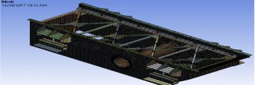
Fig1. Inline knockout machine
A very erratic motion is developed when this wheel is rotated. A double counterbalance system is used in the horizontal screen. The counterbalance weight will alternately promote and retard the direction of vibration depending upon where within each revolution the weights come opposite each other. The first sign that an operator has indicating that the fatigue in the body of the screen deck is almost at a critical stage in its development are the hairline cracks that will appear around the vibration’s point of origin.
III.MODELINGOFTHECOMPONENTS
The vibrating box is divided into two parts: Vibrating frame and screen frame. Because of the complex of structure and too many parts of screen and screen frame, the finite element models of them are very difficult to be building by using the ANSYS. Because CAD is mature and operational software, it can quickly create virtual models of screen and screen frame. Therefore, the combination of CAD and ANSYS is very necessary for analysing vibrating screen. The CAD model was changed into a standard format which can be imported into ANSYS in order to get finite element model. CATIA v5 is able to read and produce STEP format files for reverse technological innovation and surface recycling [4].The following simplified steps are taken:
(a) Some small connectors, fixing bracket, other non-bearing components and functional parts are omitted.
(b) All chamfers, fillets, rivets and welding spots are ignored which are not the major factors to reduce the workload of the modelling.
309 | P a g e (d) The parts of screen box are thin-walled plate except the motor base.
IV. PREPROCESSING
A. Connections And Preloading –
Import the modal in the ANSYS for the analysis purpose. Auto connection feature is used to define all the connection of the geometry. Spring is used as one more connection for dampers; there are two types of springs
1. body-body type 2.Body- ground type.
We have used body-ground type spring here, in this type of spring reference is grounded (fixed) to the ground i.e there is no any directional moment along any side of body, it will act as base of spring damper. Scoping- the working part of spring is considered as mobile direction of body, the direction in which spring is going to experience compression or expansion. By considering all above explanation constraints of spring will be GROUND to part 325121 00 003 (upper part of spring damper support)
Stiffness of spring 120.94 N/mm^2 is used as one of the input characteristic of spring. Preloading i.e approximate load which is acting on the spring is also considered in the analysis because spring may suffer pre deformation due the load applied by the whole structure. Approximately 3 ton preload is applied on the spring.in this analysis only one spring is considered as working condition.
B. Meshing of Model
Imported model from CATIA is required to mesh for further analysis. Efforts are made to achieve finer mesh for accuracy of results. For meshing first auto mesh is generated, face sizing and edge sizing is applied on the edges of circular part and face sizing is applied on side walls of the box. Mesh is hex dominant in meshing number of nodes formed are 403425 and number of elements are 57722.
Fig 2. Meshed model of inline knockout machine
V.MODALANALYSIS
Modal analysis is used to determine a structure’s vibration characteristics natural frequencies and mode shapes. Different mode shapes for different frequencies of structure can be determined in modal analysis. The purpose of natural characteristic analysis is to avoid resonance and harmful vibration modes and improve the reliability and service life of screen and screen frame [6]. For a free vibration analysis, the natural circular frequencies ωi and mode shapes Øi are calculated from the equation.
Following assumptions are made to use this equation-
• {F} is not present, so no excitation of the structure is assumed
• The structure can be unconstrained (rigid-body modes present) or partially/fully constrained, depending on the physical structure
• Mode shapes are Øi - i is corresponding mode number.
• ωi -natural frequency
• [K]- stiffness matrix [M] -mass matrix
In modal analysis we have considered first ten modes of vibration for analysis. Maximum 10 modes to find under frequency range 0-10 Hz. We can check the behavior of structure at higher frequency but the natural frequency of the structure is 4 Hz, so only frequency range up to 10 Hz is considered.
TABLE I BEHAVIOR OF THE SYSTEM FOR FIRST TEN MODE AND ITS CORRESPONDING FREQUENCIES.
Mode Effect Name of part Deformation(mm)
1
Minimum 325 121 00 005 Default<As Machined>
2.9041e-010
Maximum 325 121 00 013 Default<As Machined>-32
223.78
2
Minimum 325 121 00 005Default<As Machined>
1.5326e-010
Maximum 325 121 00 013-6
130.58
3 Minimum
325 121 00
005_Default<A
s Machined>
1.4019e-010
Maximum
325 121 00
013_Default<A
s Machined>-7
118.14
4 Minimum
325 121 00
013_Default<A
s Machined>-30
8.3181e-009
Maximum 325 121 00 003 4.4984
5 Minimum
325 121 00
005_Default<A
s Machined>
7.3041e-010
Maximum
325 121 00
013_Default<A
172.27
310 | P a g e s Machined>-6
6 Minimum
325 121 00
005_Default<A
s Machined>
1.7307e-010
Maximum
325 121 00
013_Default<A
s Machined>-6
177.57
7
Minimum
325 121 00 005_Default<A
s Machined> 3.2495e-010
Maximum 325 121 00 013_Default<A s Machined>-35
168.73
8
Minimum 325 121 00 005 2.1918e-010
Maximum
325 121 00
013_Default<A
s Machined>-8
196.7
9
Minimum
325 121 00
005_Default<A
s Machined>
1.7127e-009
Maximum
325 121 00
013_Default<A
s Machined>-30
151.72
10
Minimum
325 121 00
018_Default<A
s Machined>-1
3.879e-011
Maximum 325 121 00 019 49.66
Fig 3-Total deformation-1 at frequency 0 HZ
Fig 4- Total deformation -10 at frequency 0.00060832 Hz .
TABLE II DIFFERENT MODES OF NATURAL FREQUENCIES
Mode Frequenc
y [Hz] Characteristic Of Vibration Mode
1.
0
Rigid motion (translational motion, pitch vibration) along x,y,z axis at second compartment.
2.
Rigid motion along x,y,z axis, at fourth compartment.
3. Rigid motion along x,y,z axis, at third compartment.
4. Displacement at damper support. 5. Rigid motion along x,y,z axis, at fourth
compartment. 6.
7.
0.000232 Rigid motion along x,y,z axis, at third compartment.
8. 0.000556 Rigid motion along x,y,z axis, at first compartment.
9. 0.000589 Rigid motion x,y,z axis, at third compartment
10. 0.000608 Rigid motion along x,y,z axis, supporting L plates of screen
TABLE III NOMENCLATURE OF COMPONENTS Sr
no
Component number Component name
1 325 121 00 005 Default<As Machined>
Supporting parts of damper at ground
2 325 121 00 013 Default<As Machined>-32
Vibrating frame –second compartment
3 325 121 00 013_Default<As Machined>-6
Vibrating frame –fourth compartment
4 325 121 00 013_Default<As Machined>-7
Vibrating frame –second compartment, horizontal section
5 325 121 00 013_Default<As
Machined>-30 Vibrating frame –third
compartment
311 | P a g e 7 325 121 00 013_Default<As
Machined>-35
Vibrating frame –third compartment
8 325 121 00013_Default<As Machined>-8
Vibrating frame –first compartment Horizontal section
9 325 121 00 013_Default<As Machined>-30
Vibrating frame –third compartment
Inclined section
10 325 121 00 018_Default<As
Machined>-1 Vibrating box side wall
11 325 121 00 019 Supporting L-plates of
frame
VI. HARMONIC RESPONSE ANALYSIS
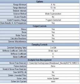
Harmonic analysis is used to determine the structural response at steady-state sinusoidal loads at a given known frequency. This will give a closer look to verify whether or not our designed part sustains the fatigue, resonance, and other harmful effects of forced vibrations. Harmonic or frequency response analysis considers only one frequency loading[5]. The loads may not be in phase with each other, but the excitation is at a known frequency. This process is not used for any transient load. Before performing harmonic analysis, always run modal analysis to gain an understanding of the dynamic behavior of the model. For the following analysis the frequency range considered is in between 0-10Hz with solution interval 10.constant damping ratio is 0.0002.
Fig 5- forces applied on vibrating screen
VII. TOTAL DEFORMATION
Considering above inputs,for the first mode maximum deformation is 13.751 mm and minimum is 4.25e-012 mm on part 325 121 00 005 and 325 121 00 018-7 respectively.In second mode of vibration on part 325 121 00 018-7 maximum effect of vibration can be seen which is 19.415mm and on part 325 121 00 005 minimum deformation 1.951e-012mm is observed.for the third mode maximum and minimum deformation is 65.65mm and 6.23e-012mm respectively on parts 325 121 00 014 and 325 121 00 005.In fourth mode part 325 121 00 018-8 suffers maximum deformation of 163.26mm and 325 121 00 005 suffer minimum deformation of 5.8766e-012mm.considering fifth mode maximum deformation is 13.564 and minimum deformation is 7.59e-013mm.in sixth mode part no 325 121 00 018-8 suffers maximum deformation Of 6.933mm and part 325 121 00 005 shows mimimum deformation 4.1977e-013mm. for seventh mode maximum deformation is on 325 121 00 18 and minimum on 325 121 00 005.In eigth mode part 325 121 00 0018-4 has deformation of
3.3159mm and 325 121 00 005 part has minimum of 1.05e-013mm.Maximum 3.19mm and minimum 5.15e-014mm deformation can be seen on part 325 121 00 002 and 325 121 00 005.For last mode maximum deformation 1.72e-013mm on part 325 121 00 005 and minimum deformation 1.93mm on 325 121 00 018-5 is observed.
VIII.EQUIVALENT STRESSES
first mode of frequency in which 17.005 Mpa stress can be seen on part 325 121 00 002 and minimum stress 1.09e-011 can be seen on part 325 121 00 003.In second mode of vibration maximum equivalent stress 23.563Mpa present on 325 121 00 002 and minimum stress 1.4546e-011 on part 325 121 00 003.for third mode Maximum 208.63 Mpa von mises stresses can be seen on part 325 121 00 013-2,on part 325 121 00 003 Minimum stress of 5.44e-011Mpa.For fourth mode maximum and minimum equivalent stresses are 3057.3 Mpa and 4.04e-011 Mpa on parts 325 121 00 003 and 325 121 00 018-2 respectively. In fifth mode of vibration maximum effect can be seen on part 325 121 00 013-2 and minimum on 325 121 00 003 of 75.78 Mpa and 9.30e-012Mpa respectively. Maximum effect can be seen on part 325 121 00 018-2 which is 28.25 Mpa and minimum of 6.18e-012Mpa on 325 121 00 003 in mode 6. Considering mode 7 we can observe that maximum equivalent stress 16.896Mpa on part 325 121 00 018-8 and minimum 3.2495e-010Mpa on part 325 121 00 003 can be seen. For eighth mode, 325 121 00 018-8 and 325 121 00 003 and corresponding maximum stress 32.17 similarly minimum effect 2.189e-012Mpa. For ninth mode of vibration maximum and minimum equivalent von mises stresses are 102.22 Mpa and 3.27e-012 on part 325 121 00 018-8 and 325 121 00 005.for last mode i.e tenth mode 325 121 00 019 and 325 121 00 003 parts maximum and minimum equivalent stresses are of 19.039 Mpa and 1.94 Mpa respectively.
312 | P a g e Fig 7- Maximum total deformation for mode 1
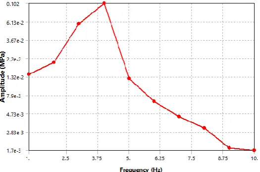
IX.FREQUENCY RESPONSE
In harmonic analysis peak response will correspond to naturel frequency .So we will consider the frequency response of the structure and will plot the graph frequency vs amplitude for 10 frequencies. Considering above statement we can infer that 4 HZ is the naturel frequency of the vibrating structure.
Fig 8- Maximum equivalent stresses for mode 4
Fig 9- Frequency Response
X.CONCLUSION
In the above failure analysis we have conducted modal analysis and harmonic analysis to understand the behavior of the components vibrating screen and vibrating box under dynamic loading.
1. From a free vibration analysis, the natural circular frequencies ωi and mode shapes Øi are calculated which will give idea about the behavior of the component (mode shape) for a particular frequency. From the above analysis we can infer that maximum deformation is seen at frequency O HZ which is 223.78 mm. Effect of this frequency is seen at second compartment of vibrating screen, which is rigid motion along x,y,z direction obtained. Minimum deformation of 49.666 mm is obtained at 0.00060832 HZ frequency. Nature of the deformation is rigid motion along x,y,z axis, supporting L plates of screen.
To avoid this maximum deformation of 223.78 mm at 0 HZ and 49.666mm at 0.00060832 HZ on corresponding components vibrating screen and supporting L plates suitable changes are required to make in the components to avoid the this maximum deformations.
2. From harmonic response analysis we can take a closer look at the behavior of the system under cyclic loading and its response such as fatigue, resonance, and other harmful effects of forced vibrations.
Maximum stress is developed at part 325 121 00 018_Default<As Machined>-2 which is maximum of 3057.3 Mpa and minimum of 4.0435e-011 Mpa on 325 121 00 003,corresponding changes are required to make in front part of vibrating box and supporting parts of dampers to avoid this stress concentration on the part.
Maximum deformation is developed at part 325 121 00 018_Default<As Machined>-8 which is maximum of 163.26 mm and minimum of 5.8766e-012 mm on 325 121 00 005_Default<As Machined>. Corresponding changes are required to make in to front part of vibrating box and supporting parts of dampers avoid this deformation on the part so that the part can resist these deformations.
3.In frequency response peak response will correspond to naturel frequency .So we will consider the frequency response of the structure, we can conclude from graph frequency vs amplitude that 4 HZ is the naturel frequency of the vibrating structure.
313 | P a g e ACKNOWLEDGMENT
I would like to express my deep sense of gratitude to my guide Prof.M.V.Kavade for his invaluable and inspiring suggestions. I would also like to thank Prof.S.B,Kumbhar for his valuable suggestions. I would also like to express my deep sense of gratitude to my industrial guide Mr.Navnath pawar for allowing to conduct the project in VIJAY Engineers and Fabricators, Shiroli and sharing his valuable industrial experience. I acknowledge with thanks, the assistance provided by central library, staff and CAD/CAM lab.
REFERENCES
1.Mr Boitumelo Ramatsetse “Failure And Sensitivity Analysis Of A Reconfigurable Vibrating Screen Using Finite Element Analysis”, “Case Studies In Engineering Failure Analysis”.
2. Sergio Baragetti “Innovative Structural Solution For Heavy Loaded Vibrating Screens”, Minerals Engineering 84 (2015) 15–26.
3. Yongjun Hou, Pan Fang And Lian Zeng,“ Finite Element Analysis Of Dual-Frequency Vibrating Screen”, Advanced Materials Research Vols. 479-481 (2012) Pp 2124-2128.
4. Liu Xinyong,Cui Hongbin,Cao Pengxian,Bao Xuechun,Liu Xinyu, “TQLZ Self-Balance Vibrating Screen Static And Modal Analysis”, Advanced Materials Research Vol. 852 (2014) Pp 619-623.
5. Zhong-Jun YIN, Lei ZHANG, Bing CHEN , “Kinematic And Dynamic Analysis Of Large Coal Vibrating Screen” Applied Mechanics And Materials Vols. 105-107 (2012) Pp 444-447.
6. DING Chuanguang, SONG Fangzhen, SONG Boand Men Xiuhua,” The Finite Element Analysis Of Vibrating Screen” Applied Mechanics And Materials Vol. 141 (2012) Pp 134-138.